Page 1113 of 1456
2. Door
A: REMOVAL AND INSTALLATION
1. DOOR ASSEMBLY
1) Remove lower trim and disconnect connectors
from body harness.
2) Place a cloth or a wood block under door to
prevent damage, and support it with a jack.
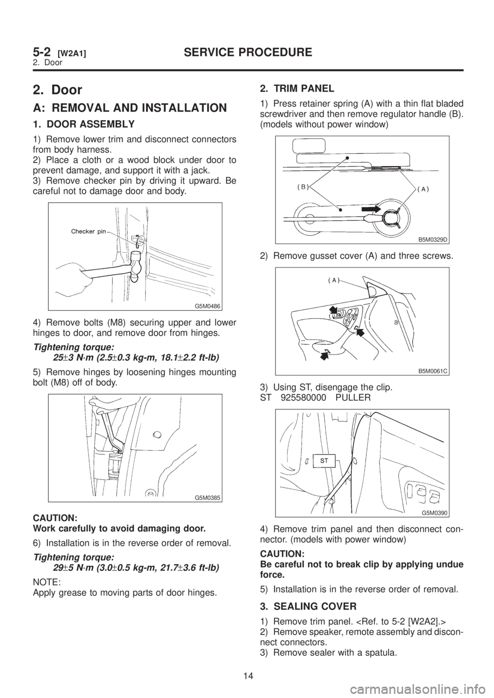
3) Remove checker pin by driving it upward. Be
careful not to damage door and body.
G5M0486
4) Remove bolts (M8) securing upper and lower
hinges to door, and remove door from hinges.
Tightening torque:
25
±3 N´m (2.5±0.3 kg-m, 18.1±2.2 ft-lb)
5) Remove hinges by loosening hinges mounting
bolt (M8) off of body.
G5M0385
CAUTION:
Work carefully to avoid damaging door.
6) Installation is in the reverse order of removal.
Tightening torque:
29
±5 N´m (3.0±0.5 kg-m, 21.7±3.6 ft-lb)
NOTE:
Apply grease to moving parts of door hinges.
2. TRIM PANEL
1) Press retainer spring (A) with a thin flat bladed
screwdriver and then remove regulator handle (B).
(models without power window)
B5M0329D
2) Remove gusset cover (A) and three screws.
B5M0061C
3) Using ST, disengage the clip.
ST 925580000 PULLER
G5M0390
4) Remove trim panel and then disconnect con-
nector. (models with power window)
CAUTION:
Be careful not to break clip by applying undue
force.
5) Installation is in the reverse order of removal.
3. SEALING COVER
1) Remove trim panel.
2) Remove speaker, remote assembly and discon-
nect connectors.
3) Remove sealer with a spatula.
14
5-2[W2A1]SERVICE PROCEDURE
2. Door
Page 1115 of 1456
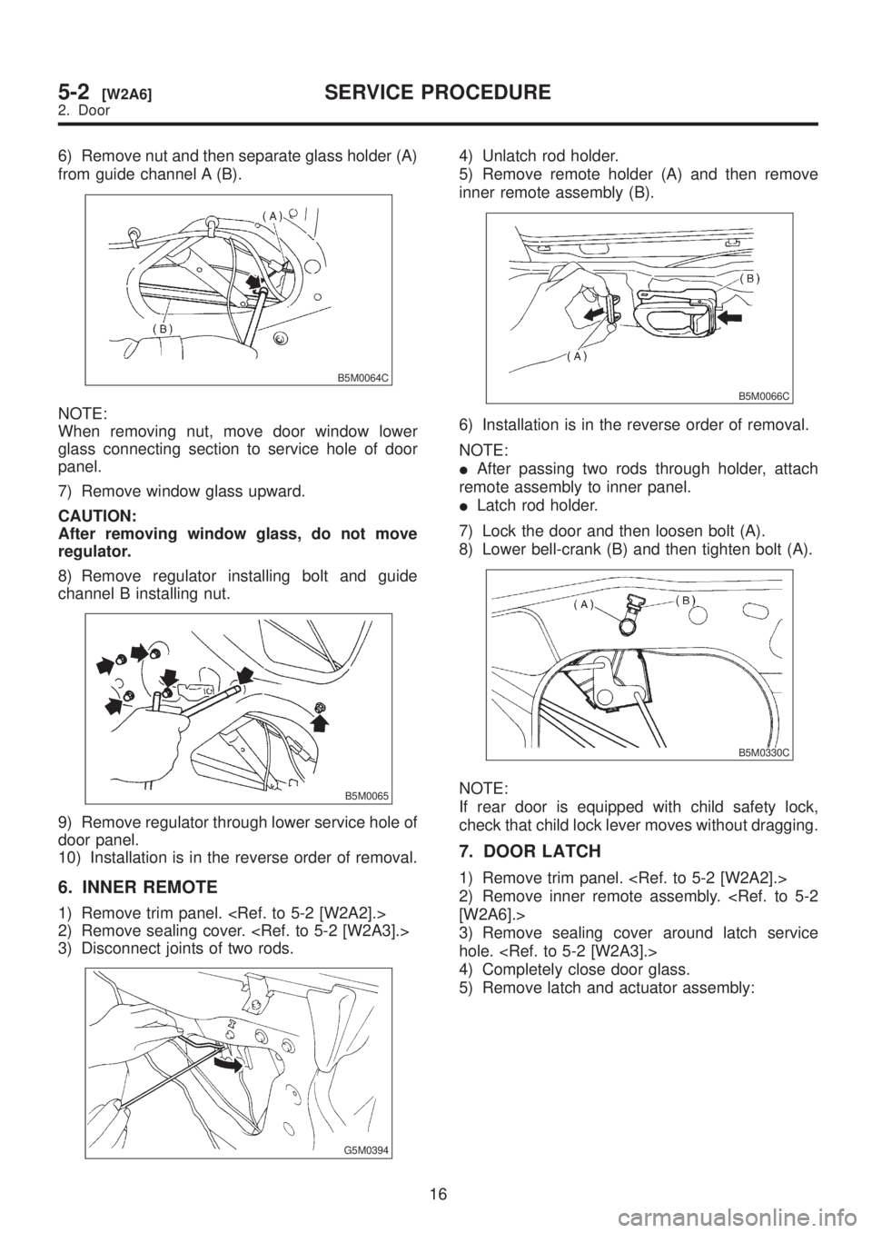
6) Remove nut and then separate glass holder (A)
from guide channel A (B).
B5M0064C
NOTE:
When removing nut, move door window lower
glass connecting section to service hole of door
panel.
7) Remove window glass upward.
CAUTION:
After removing window glass, do not move
regulator.
8) Remove regulator installing bolt and guide
channel B installing nut.
B5M0065
9) Remove regulator through lower service hole of
door panel.
10) Installation is in the reverse order of removal.
6. INNER REMOTE
1) Remove trim panel.
2) Remove sealing cover.
3) Disconnect joints of two rods.
G5M0394
4) Unlatch rod holder.
5) Remove remote holder (A) and then remove
inner remote assembly (B).
B5M0066C
6) Installation is in the reverse order of removal.
NOTE:
IAfter passing two rods through holder, attach
remote assembly to inner panel.
ILatch rod holder.
7) Lock the door and then loosen bolt (A).
8) Lower bell-crank (B) and then tighten bolt (A).
B5M0330C
NOTE:
If rear door is equipped with child safety lock,
check that child lock lever moves without dragging.
7. DOOR LATCH
1) Remove trim panel.
2) Remove inner remote assembly.
[W2A6].>
3) Remove sealing cover around latch service
hole.
4) Completely close door glass.
5) Remove latch and actuator assembly:
16
5-2[W2A6]SERVICE PROCEDURE
2. Door
Page 1116 of 1456
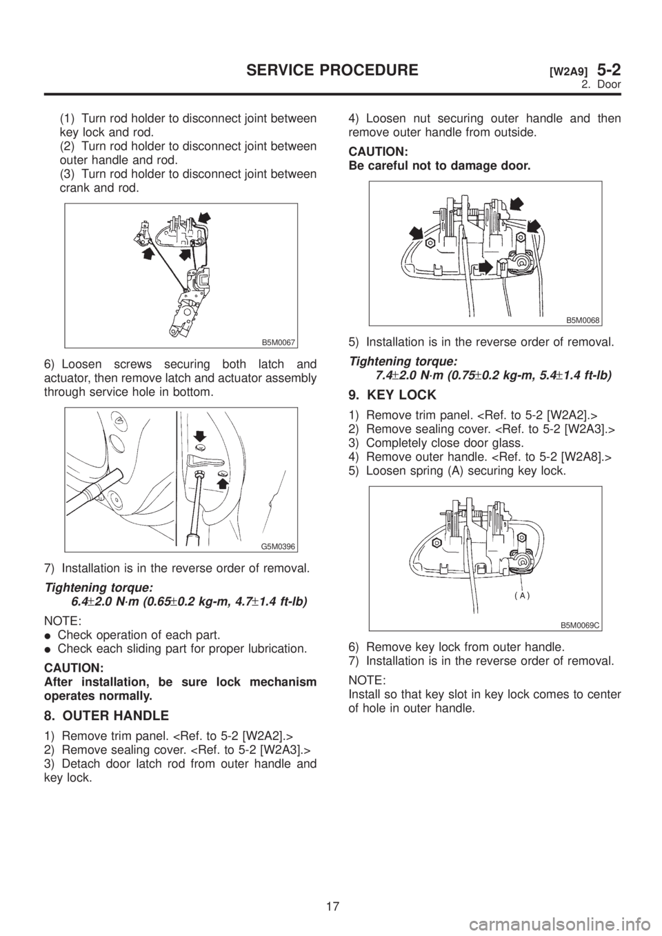
(1) Turn rod holder to disconnect joint between
key lock and rod.
(2) Turn rod holder to disconnect joint between
outer handle and rod.
(3) Turn rod holder to disconnect joint between
crank and rod.
B5M0067
6) Loosen screws securing both latch and
actuator, then remove latch and actuator assembly
through service hole in bottom.
G5M0396
7) Installation is in the reverse order of removal.
Tightening torque:
6.4
±2.0 N´m (0.65±0.2 kg-m, 4.7±1.4 ft-lb)
NOTE:
ICheck operation of each part.
ICheck each sliding part for proper lubrication.
CAUTION:
After installation, be sure lock mechanism
operates normally.
8. OUTER HANDLE
1) Remove trim panel.
2) Remove sealing cover.
3) Detach door latch rod from outer handle and
key lock.4) Loosen nut securing outer handle and then
remove outer handle from outside.
CAUTION:
Be careful not to damage door.
B5M0068
5) Installation is in the reverse order of removal.
Tightening torque:
7.4
±2.0 N´m (0.75±0.2 kg-m, 5.4±1.4 ft-lb)
9. KEY LOCK
1) Remove trim panel.
2) Remove sealing cover.
3) Completely close door glass.
4) Remove outer handle.
5) Loosen spring (A) securing key lock.
B5M0069C
6) Remove key lock from outer handle.
7) Installation is in the reverse order of removal.
NOTE:
Install so that key slot in key lock comes to center
of hole in outer handle.
17
[W2A9]5-2SERVICE PROCEDURE
2. Door
Page 1126 of 1456
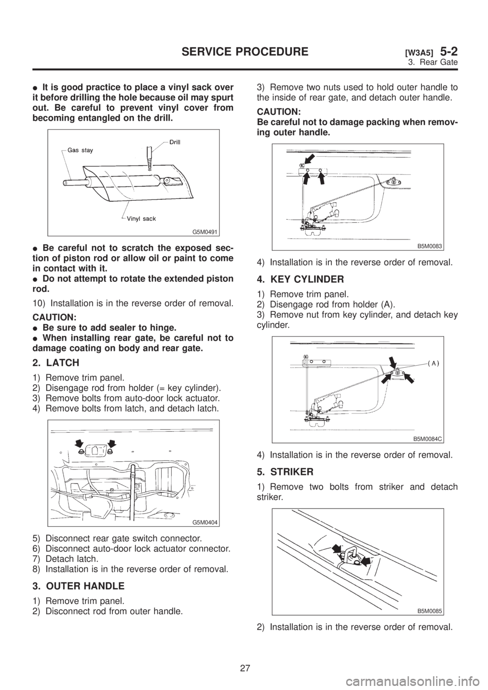
IIt is good practice to place a vinyl sack over
it before drilling the hole because oil may spurt
out. Be careful to prevent vinyl cover from
becoming entangled on the drill.
G5M0491
IBe careful not to scratch the exposed sec-
tion of piston rod or allow oil or paint to come
in contact with it.
IDo not attempt to rotate the extended piston
rod.
10) Installation is in the reverse order of removal.
CAUTION:
IBe sure to add sealer to hinge.
IWhen installing rear gate, be careful not to
damage coating on body and rear gate.
2. LATCH
1) Remove trim panel.
2) Disengage rod from holder (= key cylinder).
3) Remove bolts from auto-door lock actuator.
4) Remove bolts from latch, and detach latch.
G5M0404
5) Disconnect rear gate switch connector.
6) Disconnect auto-door lock actuator connector.
7) Detach latch.
8) Installation is in the reverse order of removal.
3. OUTER HANDLE
1) Remove trim panel.
2) Disconnect rod from outer handle.3) Remove two nuts used to hold outer handle to
the inside of rear gate, and detach outer handle.
CAUTION:
Be careful not to damage packing when remov-
ing outer handle.
B5M0083
4) Installation is in the reverse order of removal.
4. KEY CYLINDER
1) Remove trim panel.
2) Disengage rod from holder (A).
3) Remove nut from key cylinder, and detach key
cylinder.
B5M0084C
4) Installation is in the reverse order of removal.
5. STRIKER
1) Remove two bolts from striker and detach
striker.
B5M0085
2) Installation is in the reverse order of removal.
27
[W3A5]5-2SERVICE PROCEDURE
3. Rear Gate
Page 1243 of 1456
9. Room Light and Door Switch
A: REMOVAL AND INSTALLATION
1. ROOM LIGHT
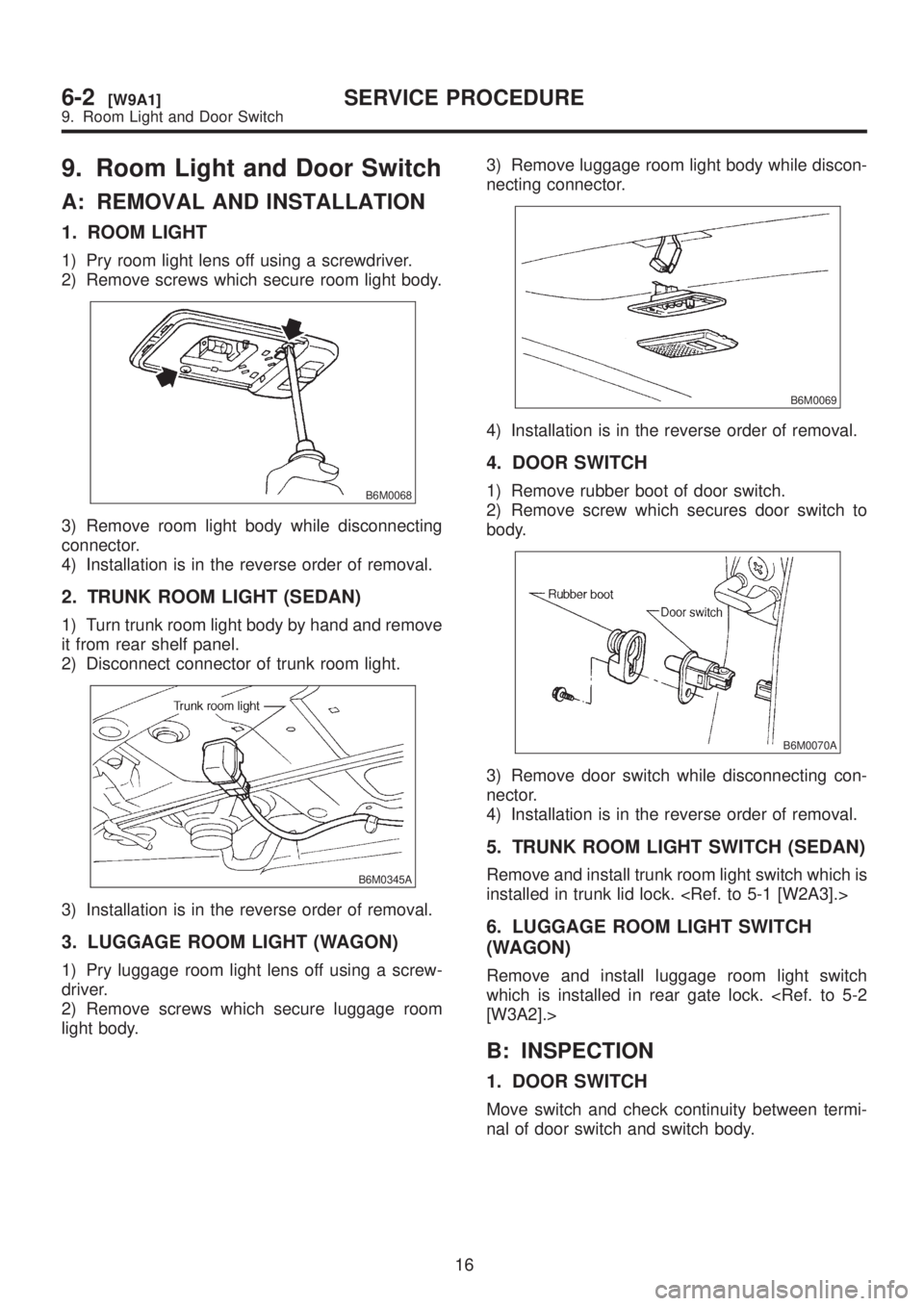
1) Pry room light lens off using a screwdriver.
2) Remove screws which secure room light body.
B6M0068
3) Remove room light body while disconnecting
connector.
4) Installation is in the reverse order of removal.
2. TRUNK ROOM LIGHT (SEDAN)
1) Turn trunk room light body by hand and remove
it from rear shelf panel.
2) Disconnect connector of trunk room light.
B6M0345A
3) Installation is in the reverse order of removal.
3. LUGGAGE ROOM LIGHT (WAGON)
1) Pry luggage room light lens off using a screw-
driver.
2) Remove screws which secure luggage room
light body.3) Remove luggage room light body while discon-
necting connector.
B6M0069
4) Installation is in the reverse order of removal.
4. DOOR SWITCH
1) Remove rubber boot of door switch.
2) Remove screw which secures door switch to
body.
B6M0070A
3) Remove door switch while disconnecting con-
nector.
4) Installation is in the reverse order of removal.
5. TRUNK ROOM LIGHT SWITCH (SEDAN)
Remove and install trunk room light switch which is
installed in trunk lid lock.
6. LUGGAGE ROOM LIGHT SWITCH
(WAGON)
Remove and install luggage room light switch
which is installed in rear gate lock.
[W3A2].>
B: INSPECTION
1. DOOR SWITCH
Move switch and check continuity between termi-
nal of door switch and switch body.
16
6-2[W9A1]SERVICE PROCEDURE
9. Room Light and Door Switch
Page 1262 of 1456
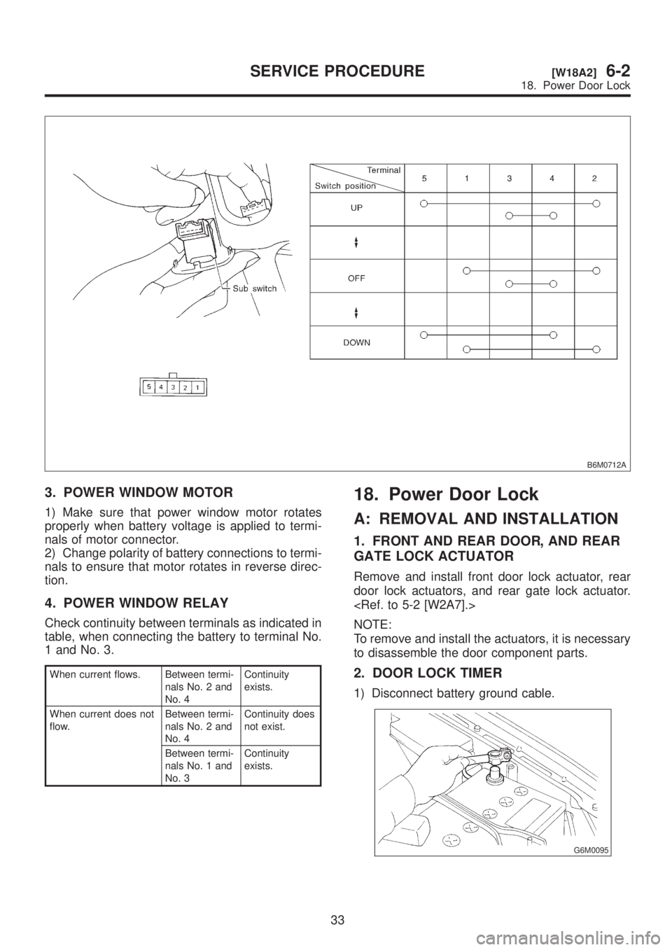
B6M0712A
3. POWER WINDOW MOTOR
1) Make sure that power window motor rotates
properly when battery voltage is applied to termi-
nals of motor connector.
2) Change polarity of battery connections to termi-
nals to ensure that motor rotates in reverse direc-
tion.
4. POWER WINDOW RELAY
Check continuity between terminals as indicated in
table, when connecting the battery to terminal No.
1 and No. 3.
When current flows. Between termi-
nals No. 2 and
No. 4Continuity
exists.
When current does not
flow.Between termi-
nals No. 2 and
No. 4Continuity does
not exist.
Between termi-
nals No. 1 and
No. 3Continuity
exists.
18. Power Door Lock
A: REMOVAL AND INSTALLATION
1. FRONT AND REAR DOOR, AND REAR
GATE LOCK ACTUATOR
Remove and install front door lock actuator, rear
door lock actuators, and rear gate lock actuator.
NOTE:
To remove and install the actuators, it is necessary
to disassemble the door component parts.
2. DOOR LOCK TIMER
1) Disconnect battery ground cable.
G6M0095
33
[W18A2]6-2SERVICE PROCEDURE
18. Power Door Lock
Page 1263 of 1456
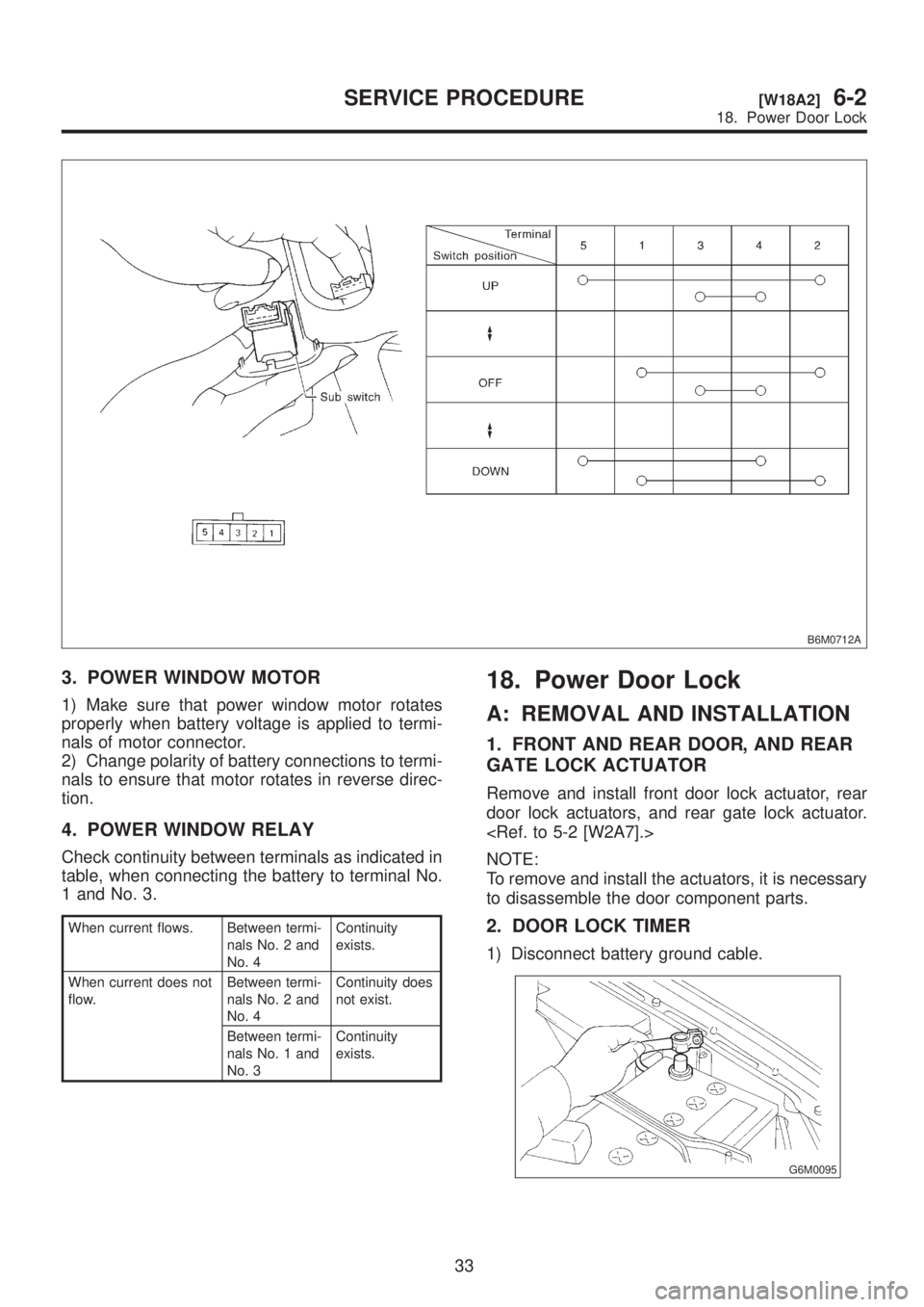
B6M0712A
3. POWER WINDOW MOTOR
1) Make sure that power window motor rotates
properly when battery voltage is applied to termi-
nals of motor connector.
2) Change polarity of battery connections to termi-
nals to ensure that motor rotates in reverse direc-
tion.
4. POWER WINDOW RELAY
Check continuity between terminals as indicated in
table, when connecting the battery to terminal No.
1 and No. 3.
When current flows. Between termi-
nals No. 2 and
No. 4Continuity
exists.
When current does not
flow.Between termi-
nals No. 2 and
No. 4Continuity does
not exist.
Between termi-
nals No. 1 and
No. 3Continuity
exists.
18. Power Door Lock
A: REMOVAL AND INSTALLATION
1. FRONT AND REAR DOOR, AND REAR
GATE LOCK ACTUATOR
Remove and install front door lock actuator, rear
door lock actuators, and rear gate lock actuator.
NOTE:
To remove and install the actuators, it is necessary
to disassemble the door component parts.
2. DOOR LOCK TIMER
1) Disconnect battery ground cable.
G6M0095
33
[W18A2]6-2SERVICE PROCEDURE
18. Power Door Lock
Page 1264 of 1456
2) Remove lower cover and then disconnect con-
nector.
B3M0377A
3) Remove door lock timer (A) while disconnecting
connector.
B6M0683C
4) Installation is in the reverse order of removal.
Tightening torque:
7.4
±2.5 N´m (0.75±0.25 kg-m, 5.4±1.8 ft-lb)
B: INSPECTION
1. DOOR LOCK SWITCH (DRIVER'S AND
FRONT PASSENGER'S DOOR)
1) Remove door trim panel. 2) Set switch to each position and check continu-
ity between terminals.
B6M0839A
2. ACTUATOR
1) Remove door trim panel.
2) Disconnect connector of actuator.
3) Make sure that door link moves to LOCK or
UNLOCK position when battery voltage is applied
between terminals:
IConnect battery positive (+) terminal to terminal
No. 2, and negative (þ) terminal to terminal No. 4
at a moment.
IConnect battery positive (+) terminal to terminal
No. 4, and negative terminal (þ) to terminal No. 2
at a moment.
B6M0135
34
6-2[W18B1]SERVICE PROCEDURE
18. Power Door Lock