Page 204 of 345
15. Sunroof
A: REMOVAL AND INSTALLATION
1. GLASS LID
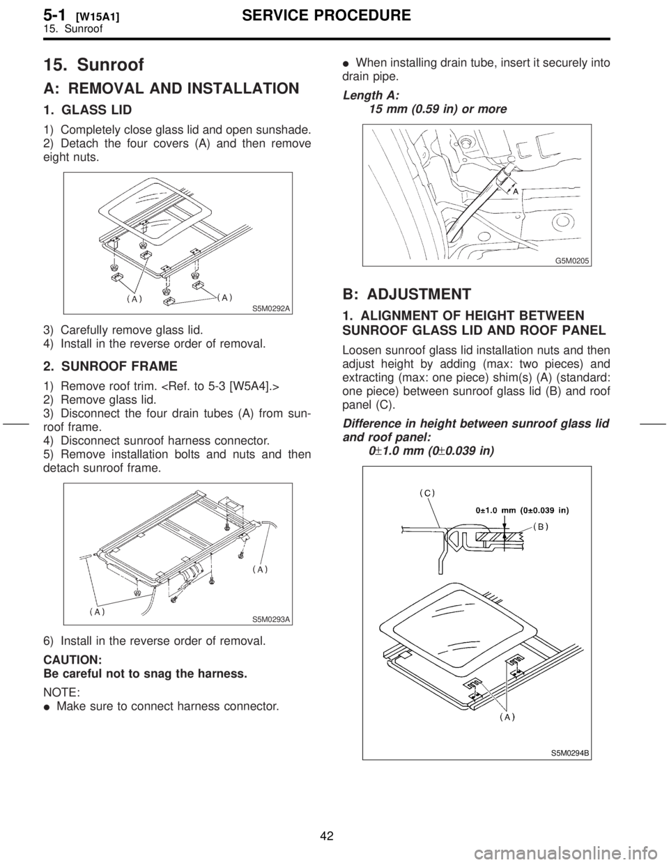
1) Completely close glass lid and open sunshade.
2) Detach the four covers (A) and then remove
eight nuts.
S5M0292A
3) Carefully remove glass lid.
4) Install in the reverse order of removal.
2. SUNROOF FRAME
1) Remove roof trim.
2) Remove glass lid.
3) Disconnect the four drain tubes (A) from sun-
roof frame.
4) Disconnect sunroof harness connector.
5) Remove installation bolts and nuts and then
detach sunroof frame.
S5M0293A
6) Install in the reverse order of removal.
CAUTION:
Be careful not to snag the harness.
NOTE:
IMake sure to connect harness connector.IWhen installing drain tube, insert it securely into
drain pipe.
Length A:
15 mm (0.59 in) or more
G5M0205
B: ADJUSTMENT
1. ALIGNMENT OF HEIGHT BETWEEN
SUNROOF GLASS LID AND ROOF PANEL
Loosen sunroof glass lid installation nuts and then
adjust height by adding (max: two pieces) and
extracting (max: one piece) shim(s) (A) (standard:
one piece) between sunroof glass lid (B) and roof
panel (C).
Difference in height between sunroof glass lid
and roof panel:
0
±1.0 mm (0±0.039 in)
S5M0294B
42
5-1[W15A1]SERVICE PROCEDURE
15. Sunroof
Page 205 of 345
2. CHECKING FOR MOVEMENT OF
SUNROOF PANEL ITSELF
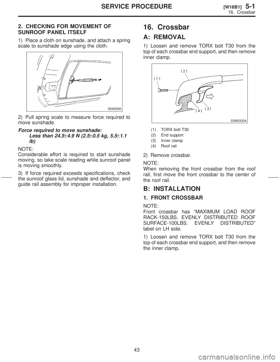
1) Place a cloth on sunshade, and attach a spring
scale to sunshade edge using the cloth.
S5M0295
2) Pull spring scale to measure force required to
move sunshade.
Force required to move sunshade:
Less than 24.5
±4.9 N (2.5±0.5 kg, 5.5±1.1
lb)
NOTE:
Considerable effort is required to start sunshade
moving, so take scale reading while sunroof panel
is moving smoothly.
3) If force required exceeds specifications, check
the sunroof glass lid, sunshade and deflector, and
guide rail assembly for improper installation.
16. Crossbar
A: REMOVAL
1) Loosen and remove TORX bolt T30 from the
top of each crossbar end support, and then remove
inner clamp.
S5M0330A
(1) TORX bolt T30
(2) End support
(3) Inner clamp
(4) Roof rail
2) Remove crossbar.
NOTE:
When removing the front crossbar from the roof
rail, first move the front crossbar to the center of
the roof rail.
B: INSTALLATION
1. FRONT CROSSBAR
NOTE:
Front crossbar has ªMAXIMUM LOAD ROOF
RACK-150LBS. EVENLY DISTRIBUTED ROOF
SURFACE-100LBS. EVENLY DISTRIBUTEDº
label on LH side.
1) Loosen and remove TORX bolt T30 from the
top of each crossbar end support, and then remove
the inner clamp.
43
[W16B1]5-1SERVICE PROCEDURE
16. Crossbar
Page 210 of 345
1. Door Alignment
S5M0380A
2
5-2[S100]SPECIFICATIONS AND SERVICE DATA
1. Door Alignment
Page 222 of 345
2. Door
A: REMOVAL AND INSTALLATION
1. DOOR ASSEMBLY
1) Remove front pillar lower trim
[W5A1].> and disconnect connectors from body
harness.
B5M0726
2) Place a cloth or a wood block under door to
prevent damage, and support it with a jack.
3) Remove checker bolt.
Tightening torque:
32
±10 N´m (3.3±1.0 kg-m, 23.9±7.2 ft-lb)
S5M0183
4) Remove bolts (M8) securing upper and lower
hinges to door, and remove door from hinges.
Tightening torque:
25
±3 N´m (2.5±0.3 kg-m, 18.1±2.2 ft-lb)
5) Remove hinges by loosening hinges mounting
bolt (M8) off of body.
Tightening torque:
29
±5 N´m (3.0±0.5 kg-m, 21.7±3.6 ft-lb)
CAUTION:
Work carefully to avoid damaging door.
G5M0385
6) Install in the reverse order of removal.
NOTE:
Apply grease to moving parts of door hinges.
14
5-2[W2A1]SERVICE PROCEDURE
2. Door
Page 223 of 345
2. TRIM PANEL
CAUTION:
Be careful not to break clip by applying undue
force.
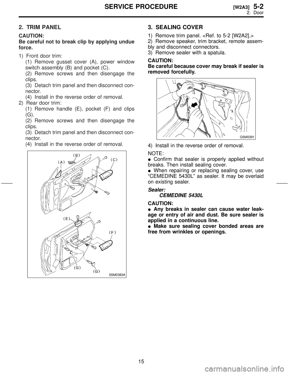
1) Front door trim:
(1) Remove gusset cover (A), power window
switch assembly (B) and pocket (C).
(2) Remove screws and then disengage the
clips.
(3) Detach trim panel and then disconnect con-
nector.
(4) Install in the reverse order of removal.
2) Rear door trim:
(1) Remove handle (E), pocket (F) and clips
(G).
(2) Remove screws and then disengage the
clips.
(3) Detach trim panel and then disconnect con-
nector.
(4) Install in the reverse order of removal.
S5M0383A
3. SEALING COVER
1) Remove trim panel.
2) Remove speaker, trim bracket, remote assem-
bly and disconnect connectors.
3) Remove sealer with a spatula.
CAUTION:
Be careful because cover may break if sealer is
removed forcefully.
G5M0391
4) Install in the reverse order of removal.
NOTE:
IConfirm that sealer is properly applied without
breaks. Then install sealing cover.
IWhen repairing or replacing sealing cover, use
ªCEMEDINE 5430Lº as sealer. It may be overlaid
on existing sealer.
Sealer:
CEMEDINE 5430L
CAUTION:
IAny breaks in sealer can cause water leak-
age or entry of air and dust. Be sure sealer is
applied in a continuous line.
IMake sure sealing cover bonded areas are
free from wrinkles or openings.
15
[W2A3]5-2SERVICE PROCEDURE
2. Door
Page 224 of 345

4. CHECKER
1) Completely close door glass.
2) Remove trim panel.
3) Remove sealing cover.
4) Remove attaching bolt to body.
5) Loosen two nuts securing checker, and take out
checker through access hole in underside.
S5M0363A
6) Install in the reverse order of removal.
Tightening torque:
T1: 7.5
±2.0 N´m (0.75±0.2 kg-m, 5.4±1.4
ft-lb)
T2: 32
±10 N´m (3.3±1.0 kg-m, 23.9±7.2
ft-lb)
5. INNER REMOTE
1) Remove trim panel.
2) Remove sealing cover.
3) Disconnect joints of two rods.
4) Unlatch rod holder.
5) Remove inner remote assembly.
S5M0186
6) Install in the reverse order of removal.
NOTE:
If rear door is equipped with child safety lock,
check that child lock lever moves without dragging.
6. DOOR LATCH AND OUTER HANDLE
1) Completely close door glass.
2) Remove door trim panel.
3) Remove inner remote assembly.
4) Remove sealing cover around latch service
hole.
5) Remove latch and actuator assembly (A):
(1) Turn rod holder to disconnect joint between
key lock and rod.
(2) Turn rod holder to disconnect joint between
outer handle and rod.
(3) Turn rod holder to disconnect joint between
crank and rod.
(4) Loosen screws securing both latch and
actuator, then remove latch and actuator
assembly through service hole in bottom.
S5M0189A
(5) Install in the reverse order of removal.
Tightening torque (screw):
6.4
±2.0 N´m (0.65±0.2 kg-m, 4.7±1.4 ft-lb)
NOTE:
ICheck operation of each part.
ICheck each sliding part for proper lubrication.
CAUTION:
After installation, be sure lock mechanism
operates normally.
16
5-2[W2A4]SERVICE PROCEDURE
2. Door
Page 225 of 345
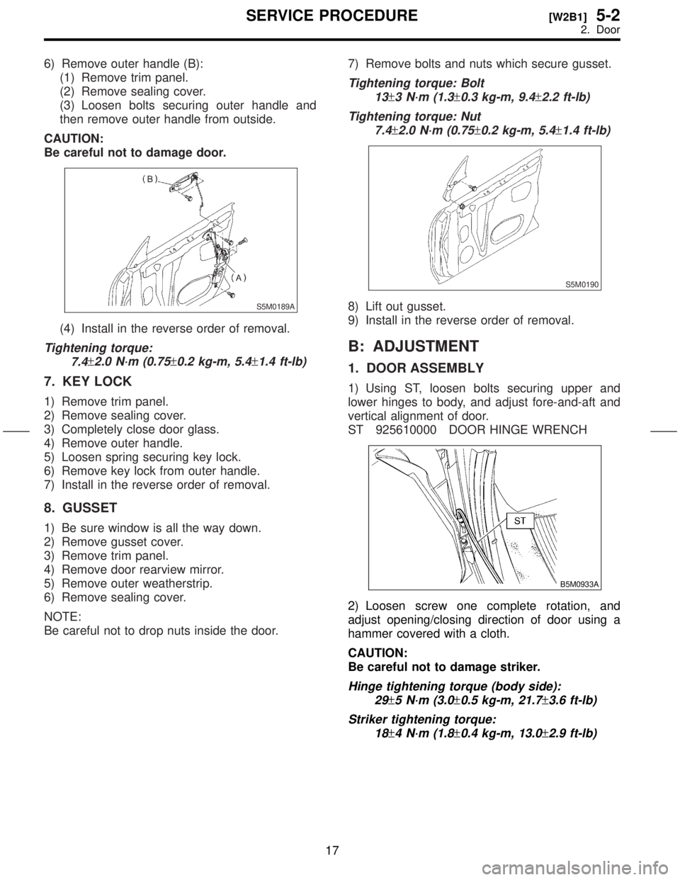
6) Remove outer handle (B):
(1) Remove trim panel.
(2) Remove sealing cover.
(3) Loosen bolts securing outer handle and
then remove outer handle from outside.
CAUTION:
Be careful not to damage door.
S5M0189A
(4) Install in the reverse order of removal.
Tightening torque:
7.4
±2.0 N´m (0.75±0.2 kg-m, 5.4±1.4 ft-lb)
7. KEY LOCK
1) Remove trim panel.
2) Remove sealing cover.
3) Completely close door glass.
4) Remove outer handle.
5) Loosen spring securing key lock.
6) Remove key lock from outer handle.
7) Install in the reverse order of removal.
8. GUSSET
1) Be sure window is all the way down.
2) Remove gusset cover.
3) Remove trim panel.
4) Remove door rearview mirror.
5) Remove outer weatherstrip.
6) Remove sealing cover.
NOTE:
Be careful not to drop nuts inside the door.7) Remove bolts and nuts which secure gusset.
Tightening torque: Bolt
13
±3 N´m (1.3±0.3 kg-m, 9.4±2.2 ft-lb)
Tightening torque: Nut
7.4
±2.0 N´m (0.75±0.2 kg-m, 5.4±1.4 ft-lb)
S5M0190
8) Lift out gusset.
9) Install in the reverse order of removal.
B: ADJUSTMENT
1. DOOR ASSEMBLY
1) Using ST, loosen bolts securing upper and
lower hinges to body, and adjust fore-and-aft and
vertical alignment of door.
ST 925610000 DOOR HINGE WRENCH
B5M0933A
2) Loosen screw one complete rotation, and
adjust opening/closing direction of door using a
hammer covered with a cloth.
CAUTION:
Be careful not to damage striker.
Hinge tightening torque (body side):
29
±5 N´m (3.0±0.5 kg-m, 21.7±3.6 ft-lb)
Striker tightening torque:
18
±4 N´m (1.8±0.4 kg-m, 13.0±2.9 ft-lb)
17
[W2B1]5-2SERVICE PROCEDURE
2. Door
Page 226 of 345
2. INNER REMOTE
1) Lock the door.
2) Loosen bolt (A).
3) Lower bell crank (B) and then tighten bolt (A).
S5M0191A
3. PROCEDURE CHART FOR ADJUSTING DOOR GLASS
H5M0912B
18
5-2[W2B2]SERVICE PROCEDURE
2. Door
![SUBARU FORESTER 1999 Service Repair Manual 1. Door Alignment
S5M0380A
2
5-2[S100]SPECIFICATIONS AND SERVICE DATA
1. Door Alignment](/manual-img/17/57427/w960_57427-209.png "SUBARU FORESTER 1999 Service Repair Manual 1. Door Alignment
S5M0380A
2
5-2[S100]SPECIFICATIONS AND SERVICE DATA
1. Door Alignment")
![SUBARU FORESTER 1999 Service Repair Manual 2. Door
A: REMOVAL AND INSTALLATION
1. DOOR ASSEMBLY
1) Remove front pillar lower trim <Ref. to 5-3
[W5A1].> and disconnect connectors from body
harness.
B5M0726
2) Place a cloth or a wood block under](/manual-img/17/57427/w960_57427-221.png "SUBARU FORESTER 1999 Service Repair Manual 2. Door
A: REMOVAL AND INSTALLATION
1. DOOR ASSEMBLY
1) Remove front pillar lower trim <Ref. to 5-3
[W5A1].> and disconnect connectors from body
harness.
B5M0726
2) Place a cloth or a wood block under")
![SUBARU FORESTER 1999 Service Repair Manual 2. INNER REMOTE
1) Lock the door.
2) Loosen bolt (A).
3) Lower bell crank (B) and then tighten bolt (A).
S5M0191A
3. PROCEDURE CHART FOR ADJUSTING DOOR GLASS
H5M0912B
18
5-2[W2B2]SERVICE PROCEDURE
2.](/manual-img/17/57427/w960_57427-225.png "SUBARU FORESTER 1999 Service Repair Manual 2. INNER REMOTE
1) Lock the door.
2) Loosen bolt (A).
3) Lower bell crank (B) and then tighten bolt (A).
S5M0191A
3. PROCEDURE CHART FOR ADJUSTING DOOR GLASS
H5M0912B
18
5-2[W2B2]SERVICE PROCEDURE
2.")