1999 SUBARU FORESTER Engine control system
[x] Cancel search: Engine control systemPage 19 of 345
![SUBARU FORESTER 1999 Service Repair Manual 5C4 : AIRBAG MAIN HARNESS INSPEC-
TION
1) Disconnect connector (AB6) from airbag control
module <Ref. to 5-5 [W6A0].>, and connect it to
test harness I or I2 connector (1I).
2) Measure resistance betw SUBARU FORESTER 1999 Service Repair Manual 5C4 : AIRBAG MAIN HARNESS INSPEC-
TION
1) Disconnect connector (AB6) from airbag control
module <Ref. to 5-5 [W6A0].>, and connect it to
test harness I or I2 connector (1I).
2) Measure resistance betw](/manual-img/17/57427/w960_57427-18.png)
5C4 : AIRBAG MAIN HARNESS INSPEC-
TION
1) Disconnect connector (AB6) from airbag control
module
test harness I or I2 connector (1I).
2) Measure resistance between test harness I or
I2 connector (2I) terminals and chassis ground.
Connector & terminal
(2I) No. 2 (+) Ð Chassis ground (þ):
S5M0278B
:Is resistance more than 1 MW?
: Go to step5C5.
: Replace airbag main harness.
5C5 : AIRBAG MAIN HARNESS INSPEC-
TION
Measure resistance between test harness I or I2
connector (2I) terminals and chassis ground.
Connector & terminal
(2I) No. 5 (+) Ð Chassis ground (þ):
S5M0279B
:Is resistance more than 1 MW?
: Replace airbag control module.
: Replace airbag main harness.
D: TROUBLE CODE 15
DIAGNOSIS:
IAirbag main harness circuit (Driver) is shorted to
power supply.
IAirbag module harness (Driver) is shorted to
power supply.
IRoll connector is shorted to power supply.
IAirbag control module is faulty.
CAUTION:
Before performing diagnostics on airbag
system, turn ignition switch ªOFFº, disconnect
battery ground terminal and then wait at least
20 seconds.
After 20 seconds elapse, remove instrument
panel lower cover, and disconnect (AB3) and
(AB8), (AB9) and (AB10).
5D1 : AIRBAG MAIN HARNESS INSPEC-
TION
1) Disconnect connector (AB6) from airbag control
module
test harness I or I2 connector (1I).
2) Connect battery ground cable and turn ignition
switch ªONº (engine off).
3) Measure voltage across each test harness I or
I2 connector (2I) terminal and chassis ground.
Connector & terminal
(2I) No. 4 (+) Ð Chassis ground (þ):
S5M0280B
:Is voltage less than 1 V?
: Go to step5D2.
: Replace airbag main harness.
20
5-5[T5C4]DIAGNOSTICS
5. Diagnostics Chart with Trouble Code
Page 20 of 345
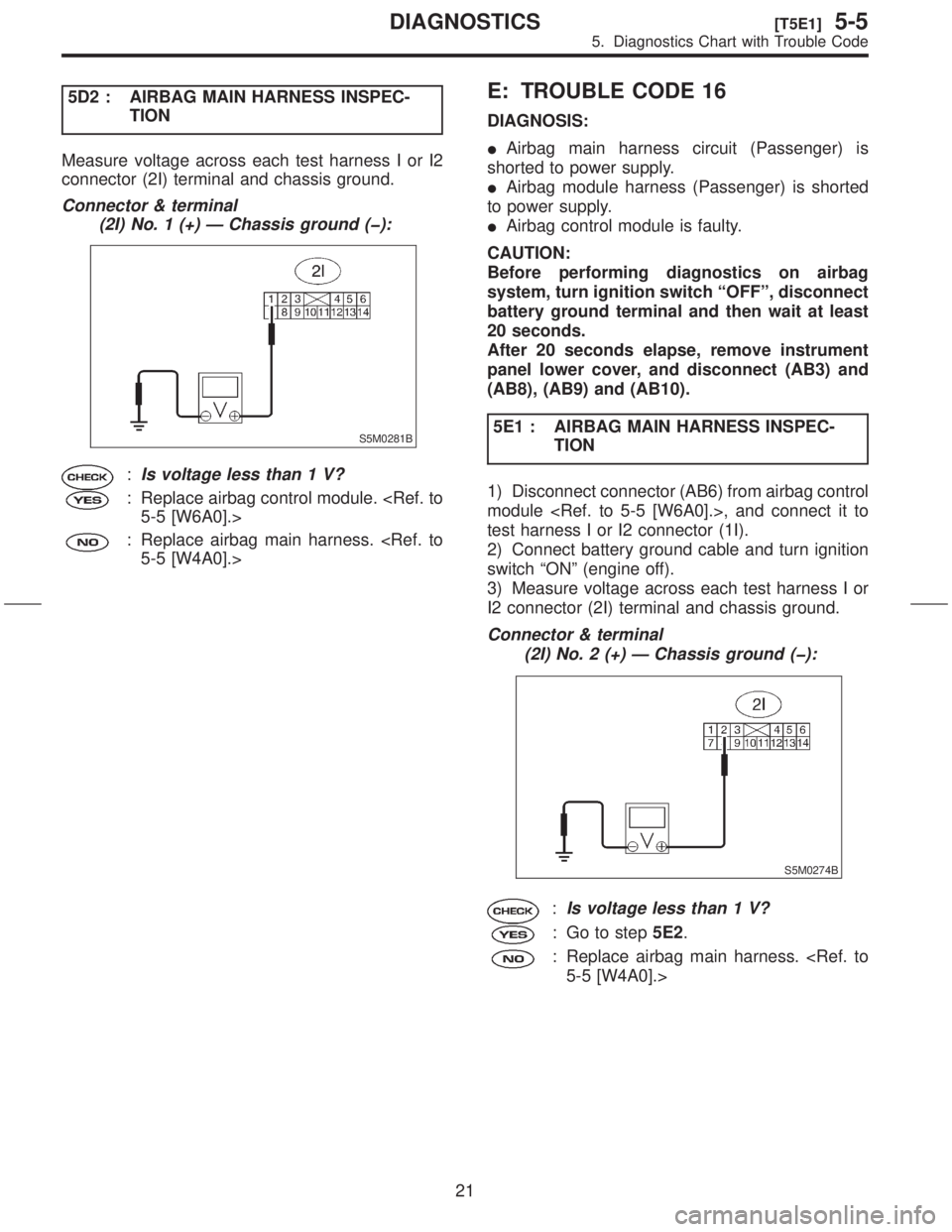
5D2 : AIRBAG MAIN HARNESS INSPEC-
TION
Measure voltage across each test harness I or I2
connector (2I) terminal and chassis ground.
Connector & terminal
(2I) No. 1 (+) Ð Chassis ground (þ):
S5M0281B
:Is voltage less than 1 V?
: Replace airbag control module.
: Replace airbag main harness.
E: TROUBLE CODE 16
DIAGNOSIS:
IAirbag main harness circuit (Passenger) is
shorted to power supply.
IAirbag module harness (Passenger) is shorted
to power supply.
IAirbag control module is faulty.
CAUTION:
Before performing diagnostics on airbag
system, turn ignition switch ªOFFº, disconnect
battery ground terminal and then wait at least
20 seconds.
After 20 seconds elapse, remove instrument
panel lower cover, and disconnect (AB3) and
(AB8), (AB9) and (AB10).
5E1 : AIRBAG MAIN HARNESS INSPEC-
TION
1) Disconnect connector (AB6) from airbag control
module
test harness I or I2 connector (1I).
2) Connect battery ground cable and turn ignition
switch ªONº (engine off).
3) Measure voltage across each test harness I or
I2 connector (2I) terminal and chassis ground.
Connector & terminal
(2I) No. 2 (+) Ð Chassis ground (þ):
S5M0274B
:Is voltage less than 1 V?
: Go to step5E2.
: Replace airbag main harness.
21
[T5E1]5-5DIAGNOSTICS
5. Diagnostics Chart with Trouble Code
Page 23 of 345
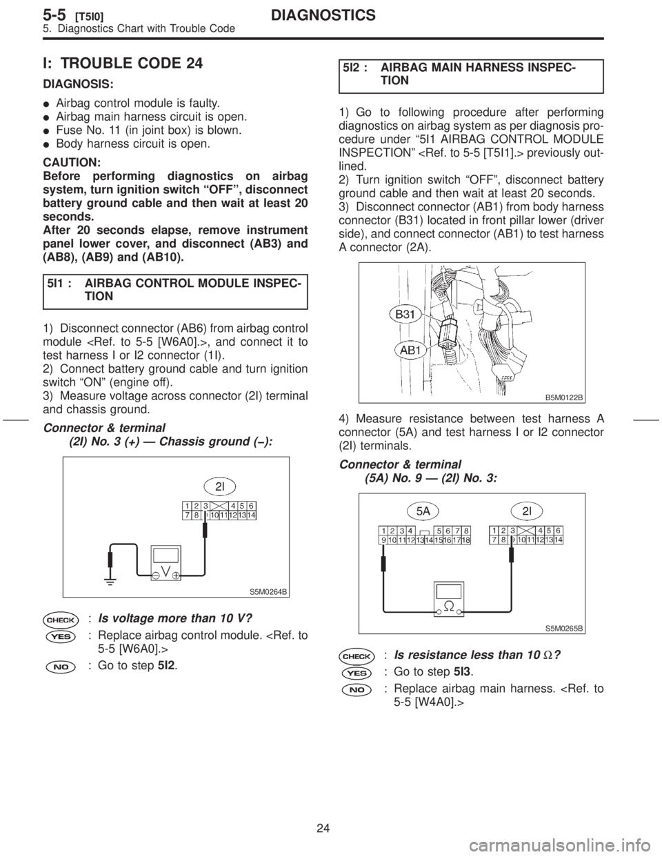
I: TROUBLE CODE 24
DIAGNOSIS:
IAirbag control module is faulty.
IAirbag main harness circuit is open.
IFuse No. 11 (in joint box) is blown.
IBody harness circuit is open.
CAUTION:
Before performing diagnostics on airbag
system, turn ignition switch ªOFFº, disconnect
battery ground cable and then wait at least 20
seconds.
After 20 seconds elapse, remove instrument
panel lower cover, and disconnect (AB3) and
(AB8), (AB9) and (AB10).
5I1 : AIRBAG CONTROL MODULE INSPEC-
TION
1) Disconnect connector (AB6) from airbag control
module
test harness I or I2 connector (1I).
2) Connect battery ground cable and turn ignition
switch ªONº (engine off).
3) Measure voltage across connector (2I) terminal
and chassis ground.
Connector & terminal
(2I) No. 3 (+) Ð Chassis ground (þ):
S5M0264B
:Is voltage more than 10 V?
: Replace airbag control module.
: Go to step5I2.5I2 : AIRBAG MAIN HARNESS INSPEC-
TION
1) Go to following procedure after performing
diagnostics on airbag system as per diagnosis pro-
cedure under ª5I1 AIRBAG CONTROL MODULE
INSPECTIONº
lined.
2) Turn ignition switch ªOFFº, disconnect battery
ground cable and then wait at least 20 seconds.
3) Disconnect connector (AB1) from body harness
connector (B31) located in front pillar lower (driver
side), and connect connector (AB1) to test harness
A connector (2A).
B5M0122B
4) Measure resistance between test harness A
connector (5A) and test harness I or I2 connector
(2I) terminals.
Connector & terminal
(5A) No. 9 Ð (2I) No. 3:
S5M0265B
:Is resistance less than 10W?
: Go to step5I3.
: Replace airbag main harness.
24
5-5[T5I0]DIAGNOSTICS
5. Diagnostics Chart with Trouble Code
Page 25 of 345
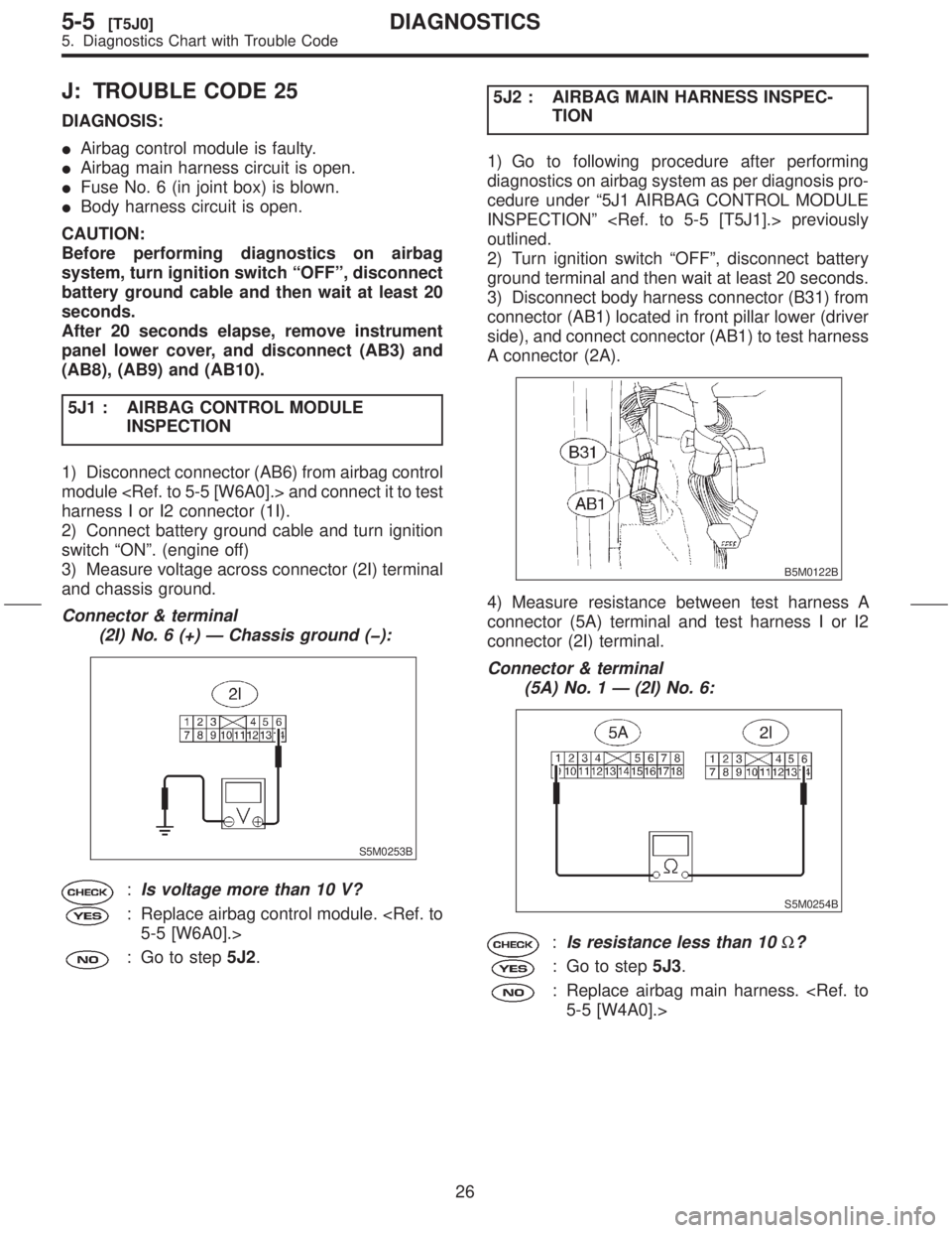
J: TROUBLE CODE 25
DIAGNOSIS:
IAirbag control module is faulty.
IAirbag main harness circuit is open.
IFuse No. 6 (in joint box) is blown.
IBody harness circuit is open.
CAUTION:
Before performing diagnostics on airbag
system, turn ignition switch ªOFFº, disconnect
battery ground cable and then wait at least 20
seconds.
After 20 seconds elapse, remove instrument
panel lower cover, and disconnect (AB3) and
(AB8), (AB9) and (AB10).
5J1 : AIRBAG CONTROL MODULE
INSPECTION
1) Disconnect connector (AB6) from airbag control
module
harness I or I2 connector (1I).
2) Connect battery ground cable and turn ignition
switch ªONº. (engine off)
3) Measure voltage across connector (2I) terminal
and chassis ground.
Connector & terminal
(2I) No. 6 (+) Ð Chassis ground (þ):
S5M0253B
:Is voltage more than 10 V?
: Replace airbag control module.
: Go to step5J2.5J2 : AIRBAG MAIN HARNESS INSPEC-
TION
1) Go to following procedure after performing
diagnostics on airbag system as per diagnosis pro-
cedure under ª5J1 AIRBAG CONTROL MODULE
INSPECTIONº
outlined.
2) Turn ignition switch ªOFFº, disconnect battery
ground terminal and then wait at least 20 seconds.
3) Disconnect body harness connector (B31) from
connector (AB1) located in front pillar lower (driver
side), and connect connector (AB1) to test harness
A connector (2A).
B5M0122B
4) Measure resistance between test harness A
connector (5A) terminal and test harness I or I2
connector (2I) terminal.
Connector & terminal
(5A) No. 1 Ð (2I) No. 6:
S5M0254B
:Is resistance less than 10W?
: Go to step5J3.
: Replace airbag main harness.
26
5-5[T5J0]DIAGNOSTICS
5. Diagnostics Chart with Trouble Code
Page 42 of 345
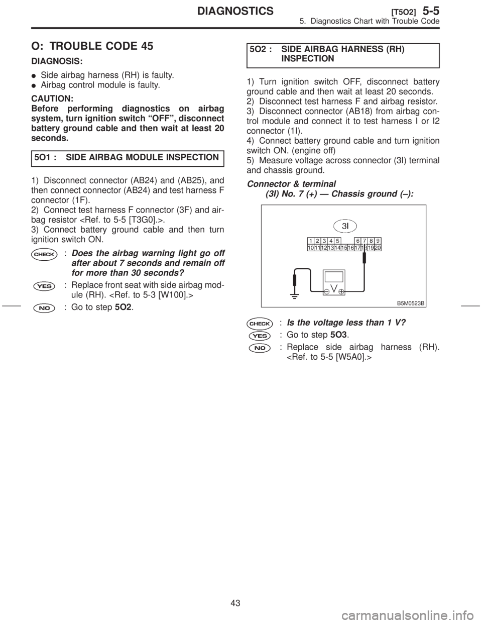
O: TROUBLE CODE 45
DIAGNOSIS:
ISide airbag harness (RH) is faulty.
IAirbag control module is faulty.
CAUTION:
Before performing diagnostics on airbag
system, turn ignition switch ªOFFº, disconnect
battery ground cable and then wait at least 20
seconds.
5O1 : SIDE AIRBAG MODULE INSPECTION
1) Disconnect connector (AB24) and (AB25), and
then connect connector (AB24) and test harness F
connector (1F).
2) Connect test harness F connector (3F) and air-
bag resistor
3) Connect battery ground cable and then turn
ignition switch ON.
:Does the airbag warning light go off
after about 7 seconds and remain off
for more than 30 seconds?
: Replace front seat with side airbag mod-
ule (RH).
: Go to step5O2.5O2 : SIDE AIRBAG HARNESS (RH)
INSPECTION
1) Turn ignition switch OFF, disconnect battery
ground cable and then wait at least 20 seconds.
2) Disconnect test harness F and airbag resistor.
3) Disconnect connector (AB18) from airbag con-
trol module and connect it to test harness I or I2
connector (1I).
4) Connect battery ground cable and turn ignition
switch ON. (engine off)
5) Measure voltage across connector (3I) terminal
and chassis ground.
Connector & terminal
(3I) No. 7 (+) Ð Chassis ground (±):
B5M0523B
:Is the voltage less than 1 V?
: Go to step5O3.
: Replace side airbag harness (RH).
43
[T5O2]5-5DIAGNOSTICS
5. Diagnostics Chart with Trouble Code
Page 57 of 345
![SUBARU FORESTER 1999 Service Repair Manual 5V8 : INSPECTION OF AIRBAG MAIN HAR-
NESS
1) Connect connectors (AB1) and (B31). Discon-
nect connector (AB6) from airbag control module
<Ref. to 5-5 [W6A0].>, and connect it to test har-
ness I or I2 SUBARU FORESTER 1999 Service Repair Manual 5V8 : INSPECTION OF AIRBAG MAIN HAR-
NESS
1) Connect connectors (AB1) and (B31). Discon-
nect connector (AB6) from airbag control module
<Ref. to 5-5 [W6A0].>, and connect it to test har-
ness I or I2](/manual-img/17/57427/w960_57427-56.png)
5V8 : INSPECTION OF AIRBAG MAIN HAR-
NESS
1) Connect connectors (AB1) and (B31). Discon-
nect connector (AB6) from airbag control module
ness I or I2 connector (1I).
2) Measure resistance between each test harness
I or I2 connector (2I) terminal and chassis ground.
Connector & terminal
(2I) No. 9 (+) Ð Chassis ground (þ):
S5M0271B
:Is resistance less than 10W?
: Go to step5V9.
: Replace airbag main harness.
5V9 : INSPECTION OF AIRBAG MAIN HAR-
NESS
Measure resistance between each test harness I
or I2 connector (2I) terminal and chassis ground.
Connector & terminal
(2I) No. 10 (+) Ð Chassis ground (þ):
S5M0272B
:Is resistance less than 10W?
: Replace airbag control module.
: Replace airbag main harness.
W: AIRBAG WARNING LIGHT
REMAINS OFF.
DIAGNOSIS:
IFuse No. 5 (in main fuse box) is blown.
IBody harness circuit is open.
IAirbag warning light is faulty.
IAirbag main harness is faulty.
IAirbag control module is faulty.
CAUTION:
Before performing diagnostics on airbag
system, turn ignition switch ªOFFº, disconnect
battery ground terminal, and then wait at least
20 seconds.
5W1 : FUSE NO. 5 (IN MAIN FUSE BOX)
INSPECTION
Remove and visually check fuse No. 5 (In main
fuse box).
S5M0273A
:Is fuse No. 5 blown?
: Replace fuse No. 5. If fuse No. 5 blows
again, Go to step5W2.
: Go to step5W2.
5W2 : BODY HARNESS INSPECTION
Turn ignition switch ªONº (engine off) to make sure
other warning lights (in combination meter) illumi-
nate.
:Do all the warning lights (in combina-
tion meter) except airbag warning
light come on?
: Go to step5W3.
: Repair body harness.
58
5-5[T5V8]DIAGNOSTICS
5. Diagnostics Chart with Trouble Code
Page 82 of 345
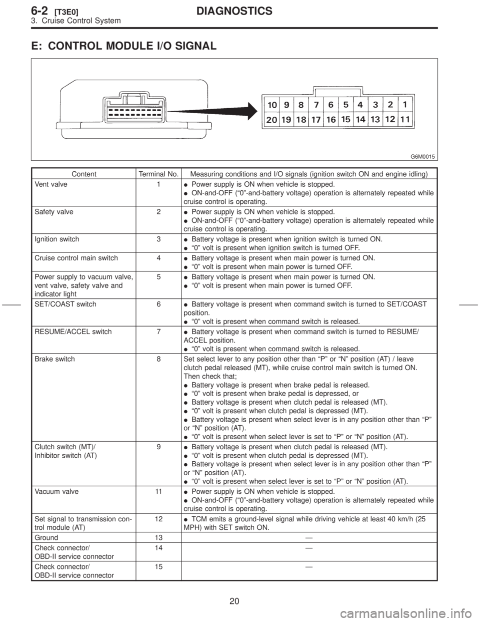
E: CONTROL MODULE I/O SIGNAL
G6M0015
Content Terminal No. Measuring conditions and I/O signals (ignition switch ON and engine idling)
Vent valve 1IPower supply is ON when vehicle is stopped.
ION-and-OFF (ª0º-and-battery voltage) operation is alternately repeated while
cruise control is operating.
Safety valve 2IPower supply is ON when vehicle is stopped.
ION-and-OFF (ª0º-and-battery voltage) operation is alternately repeated while
cruise control is operating.
Ignition switch 3IBattery voltage is present when ignition switch is turned ON.
Iª0º volt is present when ignition switch is turned OFF.
Cruise control main switch 4IBattery voltage is present when main power is turned ON.
Iª0º volt is present when main power is turned OFF.
Power supply to vacuum valve,
vent valve, safety valve and
indicator light5IBattery voltage is present when main power is turned ON.
Iª0º volt is present when main power is turned OFF.
SET/COAST switch 6IBattery voltage is present when command switch is turned to SET/COAST
position.
Iª0º volt is present when command switch is released.
RESUME/ACCEL switch 7IBattery voltage is present when command switch is turned to RESUME/
ACCEL position.
Iª0º volt is present when command switch is released.
Brake switch 8 Set select lever to any position other than ªPº or ªNº position (AT) / leave
clutch pedal released (MT), while cruise control main switch is turned ON.
Then check that;
IBattery voltage is present when brake pedal is released.
Iª0º volt is present when brake pedal is depressed, or
IBattery voltage is present when clutch pedal is released (MT).
Iª0º volt is present when clutch pedal is depressed (MT).
IBattery voltage is present when select lever is in any position other than ªPº
or ªNº position (AT).
Iª0º volt is present when select lever is set to ªPº or ªNº position (AT).
Clutch switch (MT)/
Inhibitor switch (AT)9IBattery voltage is present when clutch pedal is released (MT).
Iª0º volt is present when clutch pedal is depressed (MT).
IBattery voltage is present when select lever is in any position other than ªPº
or ªNº position (AT).
Iª0º volt is present when select lever is set to ªPº or ªNº position (AT).
Vacuum valve 11IPower supply is ON when vehicle is stopped.
ION-and-OFF (ª0º-and-battery voltage) operation is alternately repeated while
cruise control is operating.
Set signal to transmission con-
trol module (AT)12ITCM emits a ground-level signal while driving vehicle at least 40 km/h (25
MPH) with SET switch ON.
Ground 13 Ð
Check connector/
OBD-II service connector14 Ð
Check connector/
OBD-II service connector15 Ð
20
6-2[T3E0]DIAGNOSTICS
3. Cruise Control System
Page 83 of 345

Content Terminal No. Measuring conditions and I/O signals (ignition switch ON and engine idling)
Vehicle speed sensor (MT)
Automatic transmission control
module (AT)18 Lift-up the vehicle until all four wheels are raised off ground, and then rotate
any wheel manually. Approx. 5 and 0 volt pulse signals are alternately input to
cruise control module.
Stop light switch 19 Turn ignition switch to OFF. Then check that;
IBattery voltage is present when brake pedal is depressed.
Iª0º volt is present when brake pedal is released.
Ground 20 Ð
NOTE:
Voltage at terminals 1, 2, 11 and 12 cannot be checked unless vehicle is driving by cruise control operation.
21
[T3E0]6-2DIAGNOSTICS
3. Cruise Control System