Page 781 of 2267
Diagnostic ProcedureNCEC0448
1 CHECK OVERALL FUNCTION
1. Turn ignition switch ªONº.
2. Pinch fuel feed hose with fingers.
SEF143XFuel pressure pulsation should be felt on the fuel feed hose for 1 second after ignition switch is turned ªONº.
OK or NG
OK©INSPECTION END
NG©GO TO 2.
2 CHECK POWER SUPPLY
1. Turn ignition switch ªOFFº.
2. Disconnect fuel pump relay.
SEF071X3. Turn ignition switch ªONº.
4. Check voltage between terminals 1, 3 and ground with CONSULT-II or tester.
SEF144XVoltage: Battery voltage
OK or NG
OK©GO TO 4.
NG©GO TO 3.
FUEL PUMPQG16I18DE
Diagnostic Procedure
EC-339
Page 782 of 2267

3 DETECT MALFUNCTIONING PART
Check the following.
I15A fuse
IHarness for open or short between fuse and fuel pump relay
©Repair harness or connectors.
4 CHECK POWER GROUND CIRCUIT
1. Turn ignition switch ªOFFº.
2. Disconnect fuel pump harness connector.
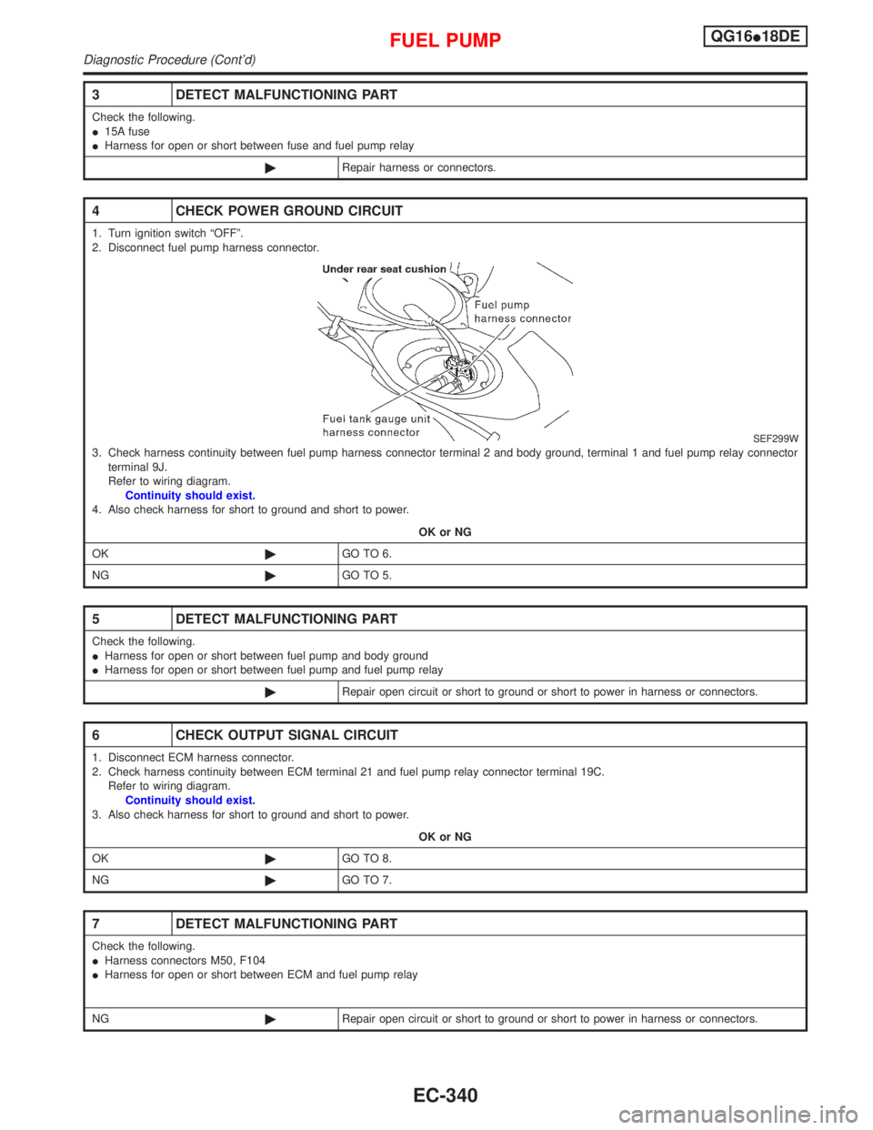
SEF299W3. Check harness continuity between fuel pump harness connector terminal 2 and body ground, terminal 1 and fuel pump relay connector
terminal 9J.
Refer to wiring diagram.
Continuity should exist.
4. Also check harness for short to ground and short to power.
OK or NG
OK©GO TO 6.
NG©GO TO 5.
5 DETECT MALFUNCTIONING PART
Check the following.
IHarness for open or short between fuel pump and body ground
IHarness for open or short between fuel pump and fuel pump relay
©Repair open circuit or short to ground or short to power in harness or connectors.
6 CHECK OUTPUT SIGNAL CIRCUIT
1. Disconnect ECM harness connector.
2. Check harness continuity between ECM terminal 21 and fuel pump relay connector terminal 19C.
Refer to wiring diagram.
Continuity should exist.
3. Also check harness for short to ground and short to power.
OK or NG
OK©GO TO 8.
NG©GO TO 7.
7 DETECT MALFUNCTIONING PART
Check the following.
IHarness connectors M50, F104
IHarness for open or short between ECM and fuel pump relay
NG©Repair open circuit or short to ground or short to power in harness or connectors.
FUEL PUMPQG16I18DE
Diagnostic Procedure (Cont'd)
EC-340
Page 783 of 2267
8 CHECK FUEL PUMP RELAY
Refer to ªComponent Inspectionº, EC-QG-341.
OK or NG
OK©GO TO 9.
NG©Replace fuel pump relay.
9 CHECK FUEL PUMP
Refer to ªComponent Inspectionº, EC-QG-341.
OK or NG
OK©GO TO 10.
NG©Replace fuel pump.
10 CHECK INTERMITTENT INCIDENT
Perform ªTROUBLE DIAGNOSIS FOR INTERMITTENT INCIDENTº, EC-QG-102.
©INSPECTION END
Component InspectionNCEC0449FUEL PUMP RELAYNCEC0449S01Check continuity between terminals 3 and 5.
Conditions Continuity
12V direct current supply between terminals 1 and 2 Yes
No current supply No
If NG, replace relay.
FUEL PUMPNCEC0449S021. Disconnect fuel pump harness connector.
2. Check resistance between terminals 1 and 2.
Resistance: 0.2 - 5.0W[at 25ÉC (77ÉF)]
If NG, replace fuel pump.
SEF145X
SEF326W
FUEL PUMPQG16I18DE
Diagnostic Procedure (Cont'd)
EC-341
Page 799 of 2267
Ignition Coil with Power TransistorNCEC0561
Terminal No. (Polarity) ResistanceW[at 25ÉC (77ÉF)]
3 (+) - 2 (þ) Except 0 or¥
1 (+) - 3 (þ)
Except 0
1 (+) - 2 (þ)
Fuel PumpNCEC0473
Resistance [at 25ÉC (77ÉF)]W0.2 - 5.0
SERVICE DATA AND SPECIFICATIONS (SDS)
Ignition Coil with Power Transistor
EC-357
Page 805 of 2267

CONSULT-II Reference Value in Data Monitor
Mode ........................................................................306
ECM Terminals and Reference Value .....................306
Wiring Diagram ........................................................308
Diagnostic Procedure ..............................................309
Component Inspection .............................................310
START SIGNAL...........................................................312
CONSULT-II Reference Value in Data Monitor
Mode ........................................................................312
ECM Terminals and Reference Value .....................312
Wiring Diagram ........................................................313
Diagnostic Procedure ..............................................314
FUEL PUMP.................................................................316
System Description ..................................................316
Component Description ...........................................316
CONSULT-II Reference Value in Data Monitor
Mode ........................................................................316
ECM Terminals and Reference Value .....................316
Wiring Diagram ........................................................317
Diagnostic Procedure ..............................................318
Component Inspection .............................................320
POWER STEERING OIL PRESSURE SWITCH.........321
Component Description ...........................................321
CONSULT-II Reference Value in Data Monitor
Mode ........................................................................321
ECM Terminals and Reference Value .....................321
Wiring Diagram ........................................................322Diagnostic Procedure ..............................................323
Component Inspection .............................................324
ELECTRICAL LOAD SIGNAL.....................................325
CONSULT-II Reference Value in Data Monitor
Mode ........................................................................325
ECM Terminals and Reference Value .....................325
Wiring Diagram ........................................................326
MI & DATA LINK CONNECTORS..............................329
Wiring Diagram ........................................................329
SERVICE DATA AND SPECIFICATIONS (SDS).......330
Fuel Pressure Regulator..........................................330
Idle Speed and Ignition Timing ................................330
Ignition Coil ..............................................................330
Mass Air Flow Sensor..............................................330
Engine Coolant Temperature Sensor ......................330
Fuel Pump ...............................................................330
IACV-AAC Valve ......................................................330
Injector .....................................................................330
Throttle Position Sensor ..........................................331
Heated Oxygen Sensor 1 (Front) Heater ................331
Intake Air Temperature Sensor ................................331
EVAP Canister Purge Volume Control Valve ..........331
Heated Oxygen Sensor 1 (Rear) Heater.................331
Crankshaft Position Sensor (OBD)..........................331
CONTENTS(Cont'd)
EC-5
Page 817 of 2267
SEF188X ECM
ECM harness
connectorGlove box
View from under the vehicleFront exhaust tube
Coolant temperature
sensor harness connector
Front
Fuel pump
harness connector
Fuel tank
gauge unit
harness connector
Under rear seat cushion
Front exhaust tubeHeated oxygen
sensor 2 (rear)
Heated oxygen sensor 2 (rear)
Harness connector
EVAP canister purge
volume control solenoid
valve
Oil filler capPower steering
oil pressure switch
EVAP canister (LHD models)
ENGINE AND EMISSION CONTROL OVERALL SYSTEMSR20DE
Engine Control Component Parts Location (Cont'd)
EC-17
Page 822 of 2267

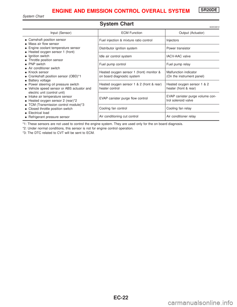
System ChartNCEC0013
Input (Sensor) ECM Function Output (Actuator)
ICamshaft position sensor
IMass air flow sensor
IEngine coolant temperature sensor
IHeated oxygen sensor 1 (front)
IIgnition switch
IThrottle position sensor
IPNP switch
IAir conditioner switch
IKnock sensor
ICrankshaft position sensor (OBD)*1
IBattery voltage
IPower steering oil pressure switch
IVehicle speed sensor or ABS actuator and
electric unit (control unit)
IIntake air temperature sensor
IHeated oxygen sensor 2 (rear)*2
ITCM (Transmission control module)*3
IClosed throttle position switch
IElectrical load
IRefrigerant pressure sensorFuel injection & mixture ratio control Injectors
Distributor ignition system Power transistor
Idle air control system IACV-AAC valve
Fuel pump control Fuel pump relay
Heated oxygen sensor 1 (front) monitor &
on board diagnostic systemMalfunction indicator
(On the instrument panel)
Heated oxygen sensor1&2(front & rear)
heater controlHeated oxygen sensor1&2
heater (front & rear)
EVAP canister purge flow controlEVAP canister purge volume con-
trol solenoid valve
Cooling fan control Cooling fan relay
Air conditioning cut control Air conditioner relay
*1: These sensors are not used to control the engine system. They are used only for the on board diagnosis.
*2: Under normal conditions, this sensor is not for engine control operation.
*3: The DTC related to CVT will be sent to ECM.
ENGINE AND EMISSION CONTROL OVERALL SYSTEMSR20DE
System Chart
EC-22
Page 831 of 2267

Fuel Pressure ReleaseNCEC0024Before disconnecting fuel line, release fuel pressure from fuel
line to eliminate danger.
WITH CONSULT-IINCEC0024S011. Start engine.
2. Perform ªFUEL PRES RELEASEº in ªWORK SUPPORTº
mode with CONSULT-II.
3. After engine stalls, crank it two or three times to release all fuel
pressure.
4. Turn ignition switch OFF.
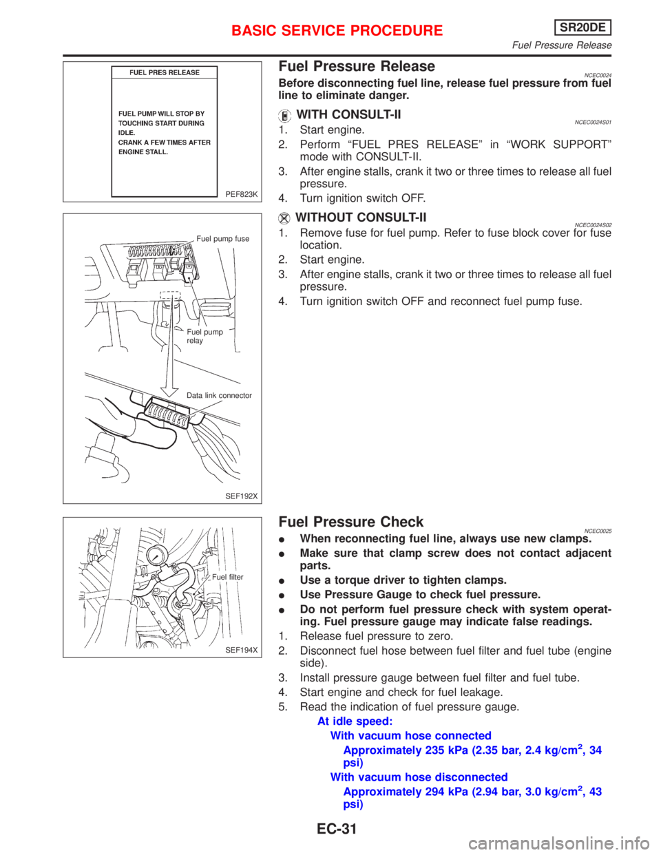
WITHOUT CONSULT-IINCEC0024S021. Remove fuse for fuel pump. Refer to fuse block cover for fuse
location.
2. Start engine.
3. After engine stalls, crank it two or three times to release all fuel
pressure.
4. Turn ignition switch OFF and reconnect fuel pump fuse.
Fuel Pressure CheckNCEC0025IWhen reconnecting fuel line, always use new clamps.
IMake sure that clamp screw does not contact adjacent
parts.
IUse a torque driver to tighten clamps.
IUse Pressure Gauge to check fuel pressure.
IDo not perform fuel pressure check with system operat-
ing. Fuel pressure gauge may indicate false readings.
1. Release fuel pressure to zero.
2. Disconnect fuel hose between fuel filter and fuel tube (engine
side).
3. Install pressure gauge between fuel filter and fuel tube.
4. Start engine and check for fuel leakage.
5. Read the indication of fuel pressure gauge.
At idle speed:
With vacuum hose connected
Approximately 235 kPa (2.35 bar, 2.4 kg/cm
2,34
psi)
With vacuum hose disconnected
Approximately 294 kPa (2.94 bar, 3.0 kg/cm
2,43
psi)
PEF823K
Fuel pump fuse
Fuel pump
relay
Data link connector
SEF192X
Fuel filter
SEF194X
BASIC SERVICE PROCEDURESR20DE
Fuel Pressure Release
EC-31