Page 1800 of 2267
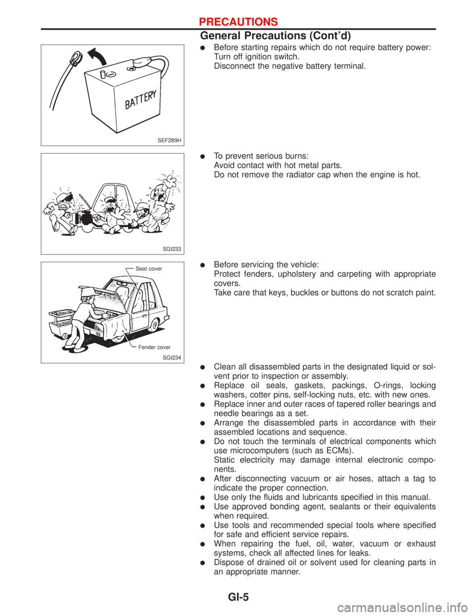
lBefore starting repairs which do not require battery power:
Turn off ignition switch.
Disconnect the negative battery terminal.
lTo prevent serious burns:
Avoid contact with hot metal parts.
Do not remove the radiator cap when the engine is hot.
lBefore servicing the vehicle:
Protect fenders, upholstery and carpeting with appropriate
covers.
Take care that keys, buckles or buttons do not scratch paint.
lClean all disassembled parts in the designated liquid or sol-
vent prior to inspection or assembly.
lReplace oil seals, gaskets, packings, O-rings, locking
washers, cotter pins, self-locking nuts, etc. with new ones.
lReplace inner and outer races of tapered roller bearings and
needle bearings as a set.
lArrange the disassembled parts in accordance with their
assembled locations and sequence.
lDo not touch the terminals of electrical components which
use microcomputers (such as ECMs).
Static electricity may damage internal electronic compo-
nents.
lAfter disconnecting vacuum or air hoses, attach a tag to
indicate the proper connection.
lUse only the fluids and lubricants specified in this manual.
lUse approved bonding agent, sealants or their equivalents
when required.
lUse tools and recommended special tools where specified
for safe and efficient service repairs.
lWhen repairing the fuel, oil, water, vacuum or exhaust
systems, check all affected lines for leaks.
lDispose of drained oil or solvent used for cleaning parts in
an appropriate manner.
SEF289H
SGI233
SGI234 Seat cover
Fender cover
PRECAUTIONS
General Precautions (Cont'd)
GI-5
Page 1978 of 2267
Special Service Tools
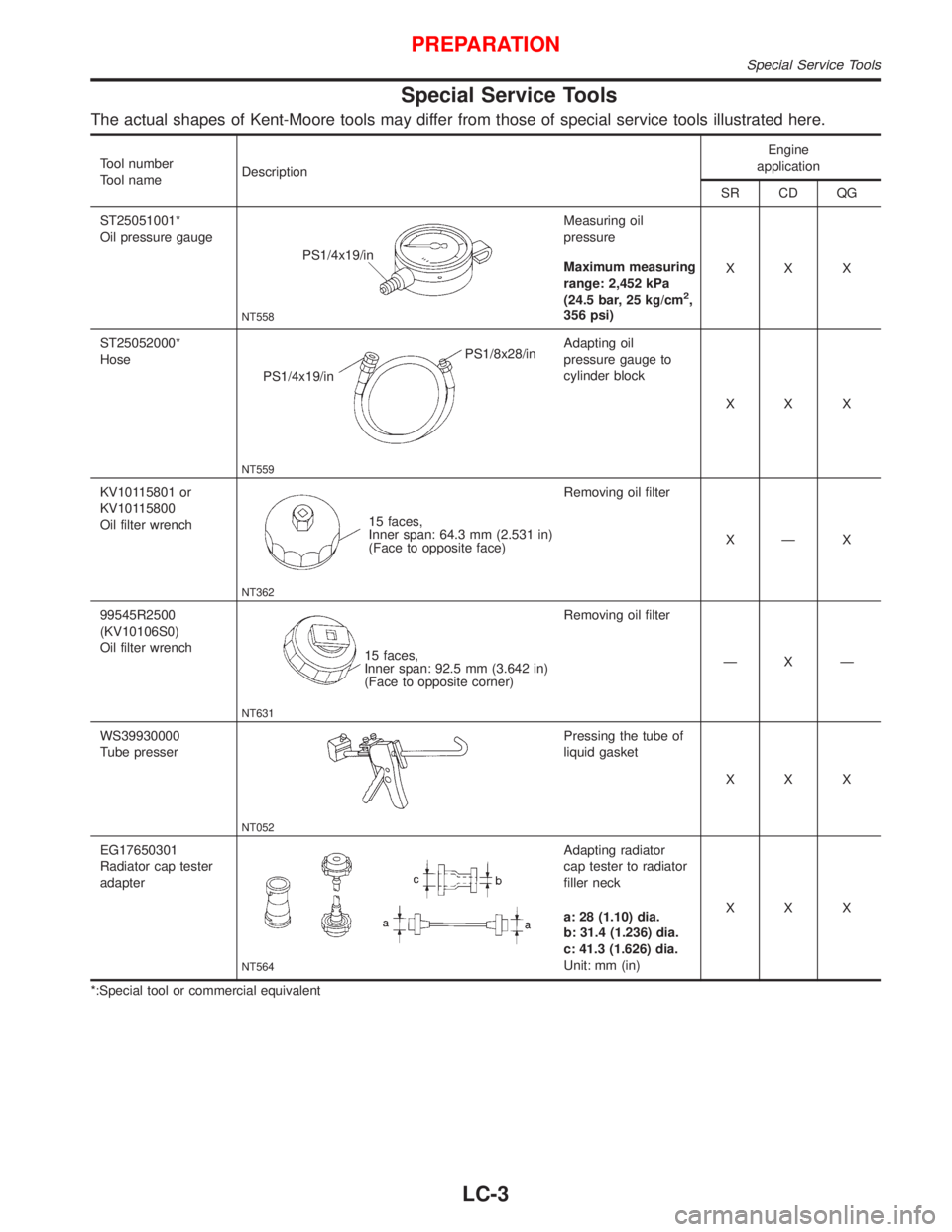
The actual shapes of Kent-Moore tools may differ from those of special service tools illustrated here.
Tool number
Tool nameDescriptionEngine
application
SR CD QG
ST25051001*
Oil pressure gauge
NT558
PS1/4x19/inMeasuring oil
pressure
Maximum measuring
range: 2,452 kPa
(24.5 bar, 25 kg/cm
2,
356 psi)XXX
ST25052000*
Hose
NT559
PS1/4x19/inPS1/8x28/inAdapting oil
pressure gauge to
cylinder block
XXX
KV10115801 or
KV10115800
Oil filter wrench
NT362
15 faces,
Inner span: 64.3 mm (2.531 in)
(Face to opposite face)Removing oil filter
X—X
99545R2500
(KV10106S0)
Oil filter wrench
NT631
15 faces,
Inner span: 92.5 mm (3.642 in)
(Face to opposite corner)Removing oil filter
—X—
WS39930000
Tube presser
NT052
Pressing the tube of
liquid gasket
XXX
EG17650301
Radiator cap tester
adapter
NT564
Adapting radiator
cap tester to radiator
filler neck
a: 28 (1.10) dia.
b: 31.4 (1.236) dia.
c: 41.3 (1.626) dia.
Unit: mm (in)XXX
*:Special tool or commercial equivalent
PREPARATION
Special Service Tools
LC-3
Page 1983 of 2267
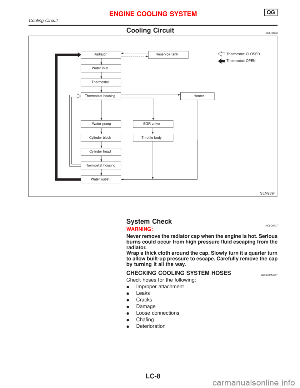
Cooling CircuitNCLC0016
System CheckNCLC0017WARNING:
Never remove the radiator cap when the engine is hot. Serious
burns could occur from high pressure fluid escaping from the
radiator.
Wrap a thick cloth around the cap. Slowly turn it a quarter turn
to allow built-up pressure to escape. Carefully remove the cap
by turning it all the way.
CHECKING COOLING SYSTEM HOSESNCLC0017S01
Check hoses for the following:
�Improper attachment
�Leaks
�Cracks
�Damage
�Loose connections
�Chafing
�Deterioration
SEM939F Radiator
Water inlet
Thermostat
Thermostat housing
Water pump
Cylinder block
Cylinder head
Thermostat housing
Water outletThrottle bodyEGR valveHeater Reservoir tankThermostat: CLOSED
Thermostat: OPEN
ENGINE COOLING SYSTEMQG
Cooling Circuit
LC-8
Page 1984 of 2267
CHECKING COOLING SYSTEM FOR LEAKSNCLC0017S02
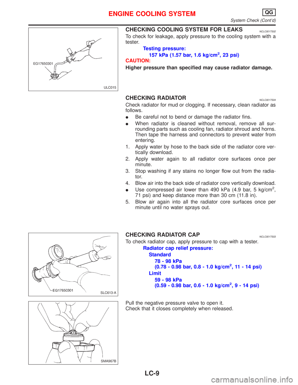
To check for leakage, apply pressure to the cooling system with a
tester.
Testing pressure:
157 kPa (1.57 bar, 1.6 kg/cm
2, 23 psi)
CAUTION:
Higher pressure than specified may cause radiator damage.
CHECKING RADIATORNCLC0017S04
Check radiator for mud or clogging. If necessary, clean radiator as
follows.
�Be careful not to bend or damage the radiator fins.
�When radiator is cleaned without removal, remove all sur-
rounding parts such as cooling fan, radiator shroud and horns.
Then tape the harness and connectors to prevent water from
entering.
1. Apply water by hose to the back side of the radiator core ver-
tically download.
2. Apply water again to all radiator core surfaces once per
minute.
3. Stop washing if any stains no longer flow out from the radia-
tor.
4. Blow air into the back side of radiator core vertically download.
�Use compressed air lower than 490 kPa (4.9 bar, 5 kg/cm
2,
71 psi) and keep distance more than 30 cm (11.8 in).
5. Blow air again into all the radiator core surfaces once per
minute until no water sprays out.
CHECKING RADIATOR CAPNCLC0017S03
To check radiator cap, apply pressure to cap with a tester.
Radiator cap relief pressure:
Standard
78-98kPa
(0.78 - 0.98 bar, 0.8 - 1.0 kg/cm
2, 11 - 14 psi)
Limit
59-98kPa
(0.59 - 0.98 bar, 0.6 - 1.0 kg/cm
2,9-14psi)
Pull the negative pressure valve to open it.
Check that it closes completely when released.
ULC015 EG17650301
SLC613-A
SMA967B
ENGINE COOLING SYSTEMQG
System Check (Cont’d)
LC-9
Page 1985 of 2267
Water Pump
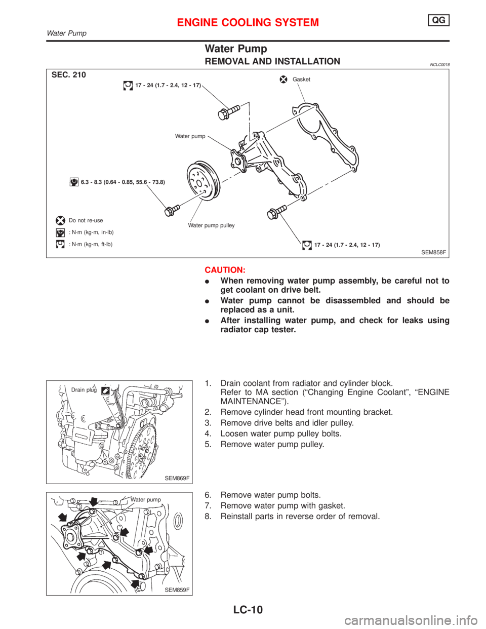
REMOVAL AND INSTALLATIONNCLC0018
CAUTION:
�When removing water pump assembly, be careful not to
get coolant on drive belt.
�Water pump cannot be disassembled and should be
replaced as a unit.
�After installing water pump, and check for leaks using
radiator cap tester.
1. Drain coolant from radiator and cylinder block.
Refer to MA section (“Changing Engine Coolant”,“ENGINE
MAINTENANCE”).
2. Remove cylinder head front mounting bracket.
3. Remove drive belts and idler pulley.
4. Loosen water pump pulley bolts.
5. Remove water pump pulley.
6. Remove water pump bolts.
7. Remove water pump with gasket.
8. Reinstall parts in reverse order of removal.
SEM858F
17 - 24 (1.7 - 2.4, 12 - 17)
Water pump
6.3 - 8.3 (0.64 - 0.85, 55.6 - 73.8)
Do not re-use
:N·m (kg-m, in-lb)
:N·m (kg-m, ft-lb)Water pump pulley
17 - 24 (1.7 - 2.4, 12 - 17)
GasketSEC. 210
SEM869F Drain plug
SEM859F Water pump
ENGINE COOLING SYSTEMQG
Water Pump
LC-10
Page 1988 of 2267
Radiator
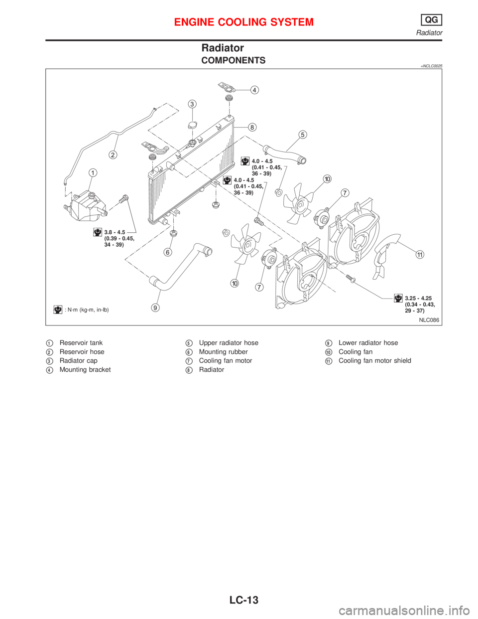
COMPONENTS=NCLC0025
�1Reservoir tank
�2Reservoir hose
�3Radiator cap
�4Mounting bracket
�5Upper radiator hose
�6Mounting rubber
�7Cooling fan motor
�8Radiator
�9Lower radiator hose
�10Cooling fan
�11Cooling fan motor shield
NLC086
:N·m (kg-m, in-lb)
3.8 - 4.5
(0.39 - 0.45,
34 - 39)
4.0 - 4.5
(0.41 - 0.45,
36 - 39)
3.25 - 4.25
(0.34 - 0.43,
29 - 37)
4.0 - 4.5
(0.41 - 0.45,
36 - 39)
ENGINE COOLING SYSTEMQG
Radiator
LC-13
Page 1996 of 2267
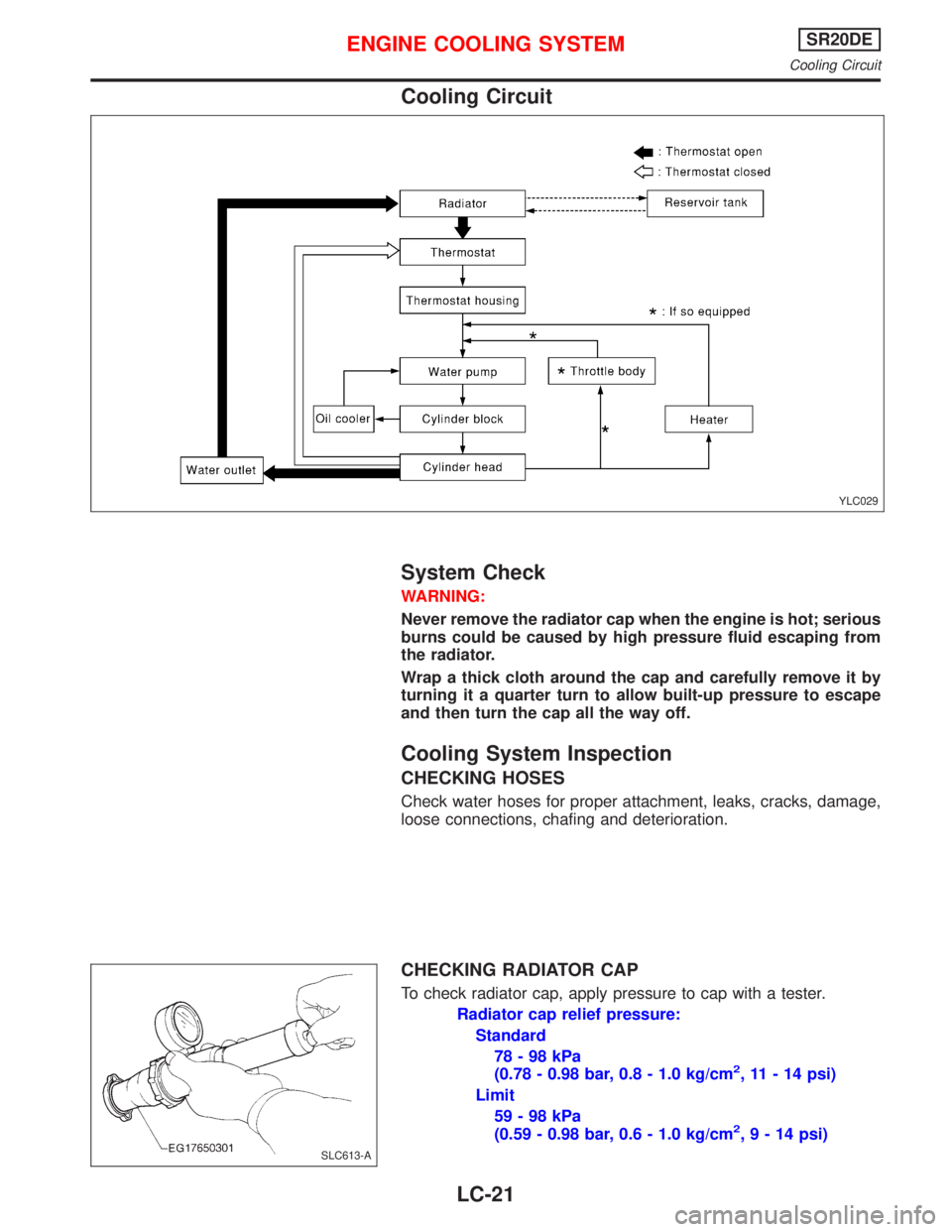
Cooling Circuit
System Check
WARNING:
Never remove the radiator cap when the engine is hot; serious
burns could be caused by high pressure fluid escaping from
the radiator.
Wrap a thick cloth around the cap and carefully remove it by
turning it a quarter turn to allow built-up pressure to escape
and then turn the cap all the way off.
Cooling System Inspection
CHECKING HOSES
Check water hoses for proper attachment, leaks, cracks, damage,
loose connections, chafing and deterioration.
CHECKING RADIATOR CAP
To check radiator cap, apply pressure to cap with a tester.
Radiator cap relief pressure:
Standard
78-98kPa
(0.78 - 0.98 bar, 0.8 - 1.0 kg/cm
2, 11 - 14 psi)
Limit
59-98kPa
(0.59 - 0.98 bar, 0.6 - 1.0 kg/cm
2,9-14psi)
YLC029
SLC613-A
ENGINE COOLING SYSTEMSR20DE
Cooling Circuit
LC-21
Page 1997 of 2267
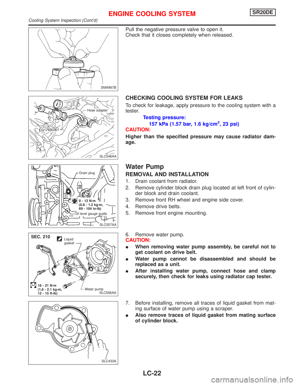
Pull the negative pressure valve to open it.
Check that it closes completely when released.
CHECKING COOLING SYSTEM FOR LEAKS
To check for leakage, apply pressure to the cooling system with a
tester.
Testing pressure:
157 kPa (1.57 bar, 1.6 kg/cm
2, 23 psi)
CAUTION:
Higher than the specified pressure may cause radiator dam-
age.
Water Pump
REMOVAL AND INSTALLATION
1. Drain coolant from radiator.
2. Remove cylinder block drain plug located at left front of cylin-
der block and drain coolant.
3. Remove front RH wheel and engine side cover.
4. Remove drive belts.
5. Remove front engine mounting.
6. Remove water pump.
CAUTION:
�When removing water pump assembly, be careful not to
get coolant on drive belt.
�Water pump cannot be disassembled and should be
replaced as a unit.
�After installing water pump, connect hose and clamp
securely, then check for leaks using radiator cap tester.
7. Before installing, remove all traces of liquid gasket from mat-
ing surface of water pump using a scraper.
�Also remove traces of liquid gasket from mating surface
of cylinder block.
SMA967B
.SLC546AA Hose adapter
.SLC557AA Drain plug
8-12N·m
(0.8 - 1.2 kg-m,
69 - 104 in-lb)
Oil level gauge guide
SLC556AA
Liquid
gasket
Water pump
16 - 21 N·m
(1.6 - 2.1 kg-m,
12 - 15 ft-lb)
SEC. 210
SLC433A
ENGINE COOLING SYSTEMSR20DE
Cooling System Inspection (Cont’d)
LC-22