Page 449 of 666
VALVE OIL SEAL
1. Remove rocker cover.
2. Remove camshaft. Refer to ªTIMING CHAINº (EM-2013).
3. Remove valve spring and valve oil seal with Tool or a suit-
able tool.
Piston concerned should be set at TDC to prevent valve
from falling.
4. Apply engine oil to new valve oil seal and install it with Tool.
OIL SEAL INSTALLING DIRECTION
lInstall new oil seal in the direction shown.
FRONT OIL SEAL
1. Remove radiator shroud and crankshaft pulley.
2. Remove front oil seal.
lBe careful not to scratch front cover.
SEM289DB
SEM290D
SEM715A
AEM385
OIL SEAL REPLACEMENTKA24DE
EM-2021
Page 453 of 666
CAUTION:
lWhen installing camshafts, chain tensioners, oil seals,
or other sliding parts, lubricate contacting surfaces with
new engine oil.
lApply new engine oil to threads and seat surfaces when
installing cylinder head, camshaft sprocket, crankshaft
pulley, and camshaft bracket.
lAttach tags to valve lifters so as not to mix them up.
lBefore removing camshaft and idler sprockets, apply
paint marks to them for retiming.
Removal
1. Drain coolant from radiator and cylinder block. Refer to MA
section (ªChanging Engine Coolantº, ªENGINE MAINTE-
NANCEº).
2. Remove upper timing chain and idler sprocket.
lRefer to ªUPPER TIMING CHAINº (EM-2015) and ªIDLER
SPROCKETº (EM-2016), ªRemovalº, ªTIMING CHAINº.
lFor retiming during cylinder head removal/installation,
apply paint marks to camshaft sprockets, upper timing
chain, lower timing chain and idler sprocket.
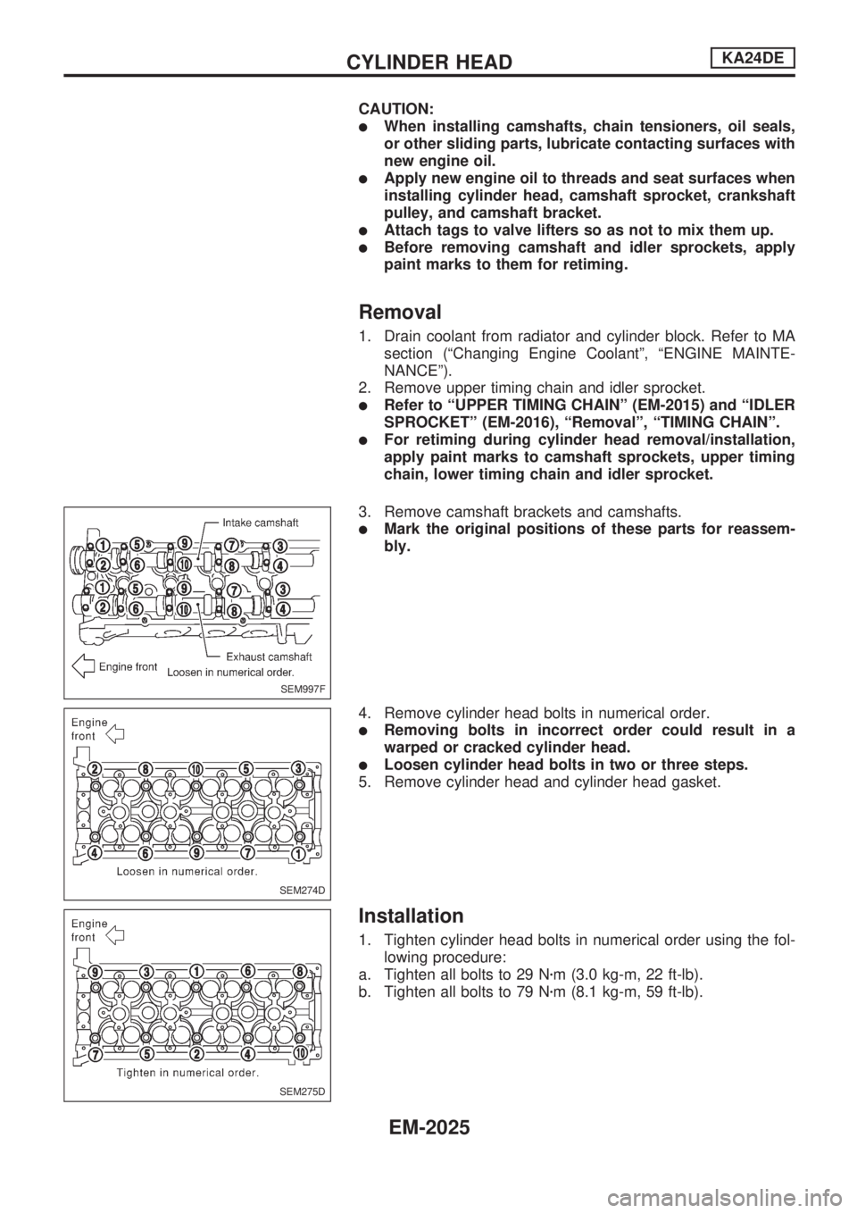
3. Remove camshaft brackets and camshafts.
lMark the original positions of these parts for reassem-
bly.
4. Remove cylinder head bolts in numerical order.
lRemoving bolts in incorrect order could result in a
warped or cracked cylinder head.
lLoosen cylinder head bolts in two or three steps.
5. Remove cylinder head and cylinder head gasket.
Installation
1. Tighten cylinder head bolts in numerical order using the fol-
lowing procedure:
a. Tighten all bolts to 29 Nzm (3.0 kg-m, 22 ft-lb).
b. Tighten all bolts to 79 Nzm (8.1 kg-m, 59 ft-lb).
SEM997F
SEM274D
SEM275D
CYLINDER HEADKA24DE
EM-2025
Page 460 of 666
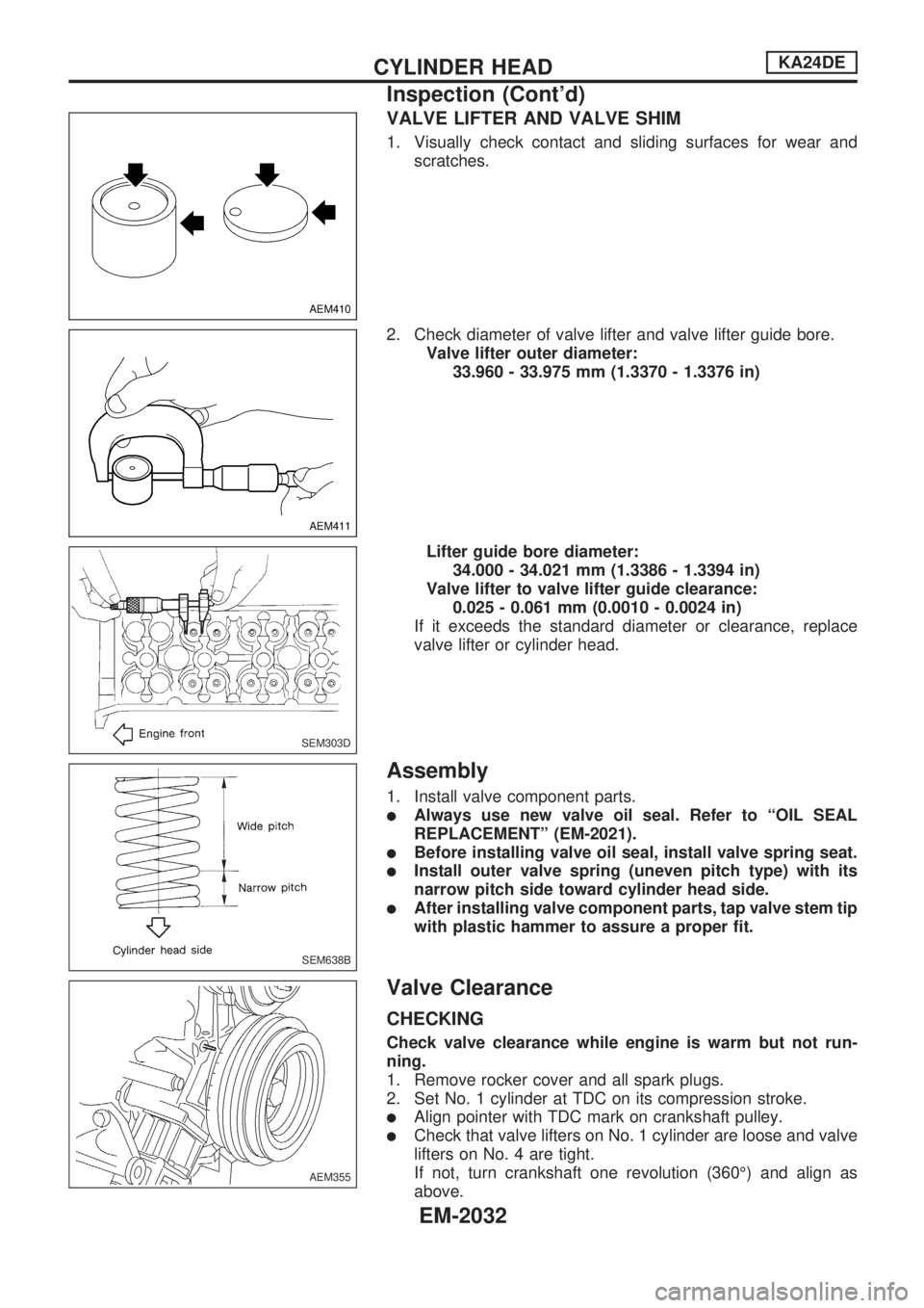
VALVE LIFTER AND VALVE SHIM
1. Visually check contact and sliding surfaces for wear and
scratches.
2. Check diameter of valve lifter and valve lifter guide bore.
Valve lifter outer diameter:
33.960 - 33.975 mm (1.3370 - 1.3376 in)
Lifter guide bore diameter:
34.000 - 34.021 mm (1.3386 - 1.3394 in)
Valve lifter to valve lifter guide clearance:
0.025 - 0.061 mm (0.0010 - 0.0024 in)
If it exceeds the standard diameter or clearance, replace
valve lifter or cylinder head.
Assembly
1. Install valve component parts.
lAlways use new valve oil seal. Refer to ªOIL SEAL
REPLACEMENTº (EM-2021).
lBefore installing valve oil seal, install valve spring seat.
lInstall outer valve spring (uneven pitch type) with its
narrow pitch side toward cylinder head side.
lAfter installing valve component parts, tap valve stem tip
with plastic hammer to assure a proper fit.
Valve Clearance
CHECKING
Check valve clearance while engine is warm but not run-
ning.
1. Remove rocker cover and all spark plugs.
2. Set No. 1 cylinder at TDC on its compression stroke.
lAlign pointer with TDC mark on crankshaft pulley.
lCheck that valve lifters on No. 1 cylinder are loose and valve
lifters on No. 4 are tight.
If not, turn crankshaft one revolution (360É) and align as
above.
AEM410
AEM411
SEM303D
SEM638B
AEM355
CYLINDER HEADKA24DE
Inspection (Cont'd)
EM-2032
Page 461 of 666
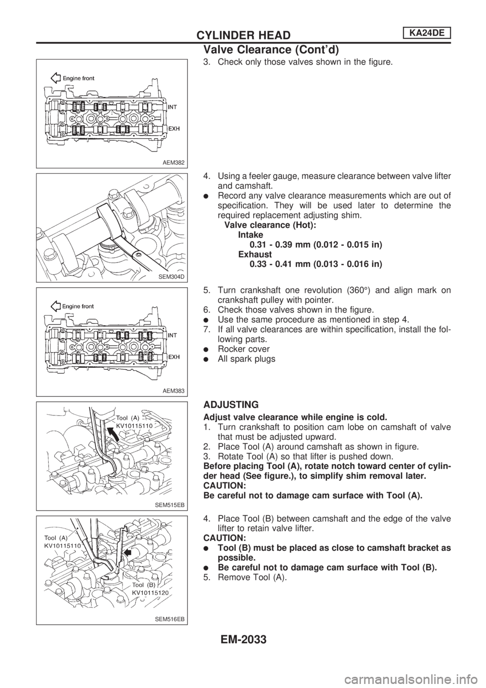
3. Check only those valves shown in the figure.
4. Using a feeler gauge, measure clearance between valve lifter
and camshaft.
lRecord any valve clearance measurements which are out of
specification. They will be used later to determine the
required replacement adjusting shim.
Valve clearance (Hot):
Intake
0.31 - 0.39 mm (0.012 - 0.015 in)
Exhaust
0.33 - 0.41 mm (0.013 - 0.016 in)
5. Turn crankshaft one revolution (360É) and align mark on
crankshaft pulley with pointer.
6. Check those valves shown in the figure.
lUse the same procedure as mentioned in step 4.
7. If all valve clearances are within specification, install the fol-
lowing parts.
lRocker cover
lAll spark plugs
ADJUSTING
Adjust valve clearance while engine is cold.
1. Turn crankshaft to position cam lobe on camshaft of valve
that must be adjusted upward.
2. Place Tool (A) around camshaft as shown in figure.
3. Rotate Tool (A) so that lifter is pushed down.
Before placing Tool (A), rotate notch toward center of cylin-
der head (See figure.), to simplify shim removal later.
CAUTION:
Be careful not to damage cam surface with Tool (A).
4. Place Tool (B) between camshaft and the edge of the valve
lifter to retain valve lifter.
CAUTION:
lTool (B) must be placed as close to camshaft bracket as
possible.
lBe careful not to damage cam surface with Tool (B).
5. Remove Tool (A).
AEM382
SEM304D
AEM383
SEM515EB
SEM516EB
CYLINDER HEADKA24DE
Valve Clearance (Cont'd)
EM-2033
Page 467 of 666
CAUTION:
lWhen installing sliding parts (bearings, pistons, etc.),
lubricate contacting surfaces with new engine oil.
lPlace removed parts such as bearings and bearing caps
in their proper order and direction.
lWhen installing connecting rod nuts and main bearing
cap bolts, apply new engine oil to threads and seating
surfaces.
lDo not allow any magnetic materials to contact the ring
gear teeth of flywheel or drive plate.
Disassembly
PISTON AND CRANKSHAFT
1. Place engine on a work stand.
2. Drain coolant and oil.
3. Remove oil pan.
4. Remove timing chain. Refer to ªRemovalº in ªTIMING
CHAINº (EM-2015).
5. Remove water pump.
6. Remove cylinder head.
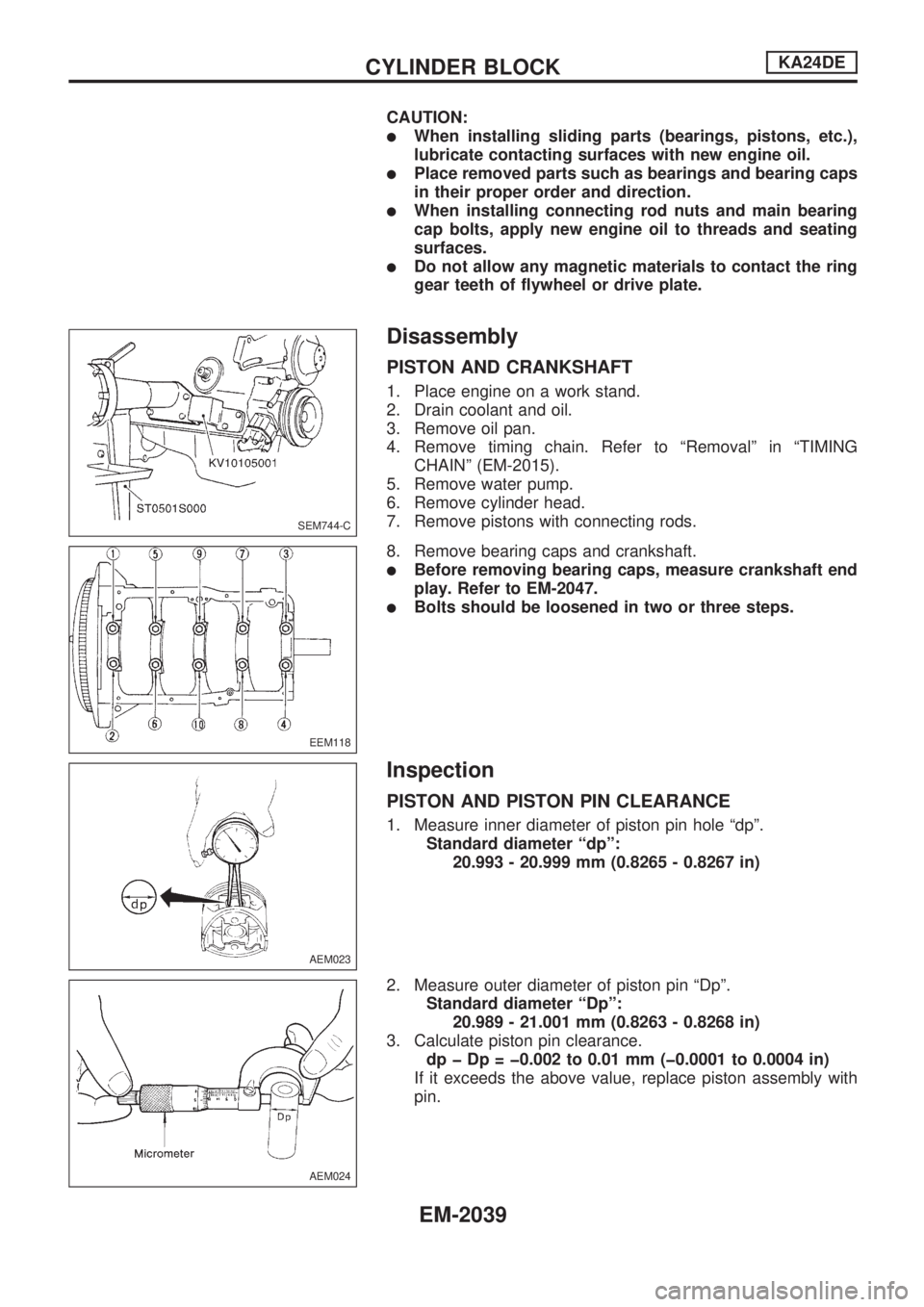
7. Remove pistons with connecting rods.
8. Remove bearing caps and crankshaft.
lBefore removing bearing caps, measure crankshaft end
play. Refer to EM-2047.
lBolts should be loosened in two or three steps.
Inspection
PISTON AND PISTON PIN CLEARANCE
1. Measure inner diameter of piston pin hole ªdpº.
Standard diameter ªdpº:
20.993 - 20.999 mm (0.8265 - 0.8267 in)
2. Measure outer diameter of piston pin ªDpº.
Standard diameter ªDpº:
20.989 - 21.001 mm (0.8263 - 0.8268 in)
3. Calculate piston pin clearance.
dp þ Dp = þ0.002 to 0.01 mm (þ0.0001 to 0.0004 in)
If it exceeds the above value, replace piston assembly with
pin.
SEM744-C
EEM118
AEM023
AEM024
CYLINDER BLOCKKA24DE
EM-2039
Page 469 of 666
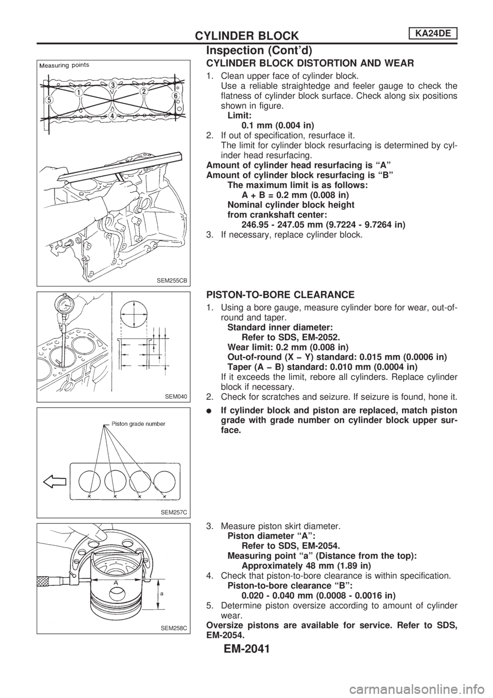
CYLINDER BLOCK DISTORTION AND WEAR
1. Clean upper face of cylinder block.
Use a reliable straightedge and feeler gauge to check the
flatness of cylinder block surface. Check along six positions
shown in figure.
Limit:
0.1 mm (0.004 in)
2. If out of specification, resurface it.
The limit for cylinder block resurfacing is determined by cyl-
inder head resurfacing.
Amount of cylinder head resurfacing is ªAº
Amount of cylinder block resurfacing is ªBº
The maximum limit is as follows:
A+B=0.2mm(0.008 in)
Nominal cylinder block height
from crankshaft center:
246.95 - 247.05 mm (9.7224 - 9.7264 in)
3. If necessary, replace cylinder block.
PISTON-TO-BORE CLEARANCE
1. Using a bore gauge, measure cylinder bore for wear, out-of-
round and taper.
Standard inner diameter:
Refer to SDS, EM-2052.
Wear limit: 0.2 mm (0.008 in)
Out-of-round (X þ Y) standard: 0.015 mm (0.0006 in)
Taper (A þ B) standard: 0.010 mm (0.0004 in)
If it exceeds the limit, rebore all cylinders. Replace cylinder
block if necessary.
2. Check for scratches and seizure. If seizure is found, hone it.
lIf cylinder block and piston are replaced, match piston
grade with grade number on cylinder block upper sur-
face.
3. Measure piston skirt diameter.
Piston diameter ªAº:
Refer to SDS, EM-2054.
Measuring point ªaº (Distance from the top):
Approximately 48 mm (1.89 in)
4. Check that piston-to-bore clearance is within specification.
Piston-to-bore clearance ªBº:
0.020 - 0.040 mm (0.0008 - 0.0016 in)
5. Determine piston oversize according to amount of cylinder
wear.
Oversize pistons are available for service. Refer to SDS,
EM-2054.
SEM255CB
SEM040
SEM257C
SEM258C
CYLINDER BLOCKKA24DE
Inspection (Cont'd)
EM-2041
Page 470 of 666
6. Cylinder bore size is determined by adding piston-to-bore
clearance to piston diameter ªAº.
Rebored size calculation:
D=A+BþC
where,
D: Bored diameter
A: Piston diameter as measured
B: Piston-to-bore clearance
C: Honing allowance 0.02 mm (0.0008 in)
7. Install main bearing caps and tighten bolts to the specified
torque. This will prevent distortion of cylinder bores.
8. Cut cylinder bores.
lWhen any cylinder needs boring, all other cylinders
must also be bored.
lDo not cut too much out of cylinder bore at a time. Cut
only 0.05 mm (0.0020 in) or so at a time.
9. Hone cylinders to obtain specified piston-to-bore clearance.
10. Measure finished cylinder bore for out-of-round and taper.
lMeasurement should be done after cylinder bore cools
down.
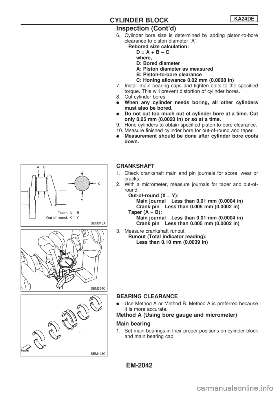
CRANKSHAFT
1. Check crankshaft main and pin journals for score, wear or
cracks.
2. With a micrometer, measure journals for taper and out-of-
round.
Out-of-round (X þ Y):
Main journal Less than 0.01 mm (0.0004 in)
Crank pin Less than 0.005 mm (0.0002 in)
Taper (A þ B):
Main journal Less than 0.01 mm (0.0004 in)
Crank pin Less than 0.005 mm (0.0002 in)
3. Measure crankshaft runout.
Runout (Total indicator reading):
Less than 0.10 mm (0.0039 in)
BEARING CLEARANCE
lUse Method A or Method B. Method A is preferred because
it is more accurate.
Method A (Using bore gauge and micrometer)
Main bearing
1. Set main bearings in their proper positions on cylinder block
and main bearing cap.
SEM316A
SEM254C
SEM448C
CYLINDER BLOCKKA24DE
Inspection (Cont'd)
EM-2042
Page 471 of 666
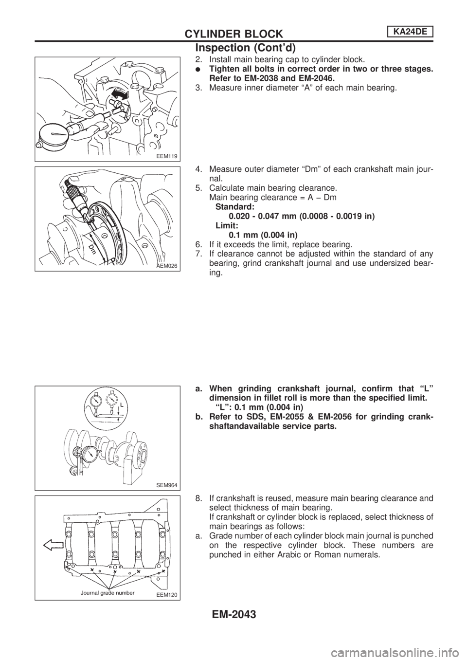
2. Install main bearing cap to cylinder block.
lTighten all bolts in correct order in two or three stages.
Refer to EM-2038 and EM-2046.
3. Measure inner diameter ªAº of each main bearing.
4. Measure outer diameter ªDmº of each crankshaft main jour-
nal.
5. Calculate main bearing clearance.
Main bearing clearance=AþDm
Standard:
0.020 - 0.047 mm (0.0008 - 0.0019 in)
Limit:
0.1 mm (0.004 in)
6. If it exceeds the limit, replace bearing.
7. If clearance cannot be adjusted within the standard of any
bearing, grind crankshaft journal and use undersized bear-
ing.
a. When grinding crankshaft journal, confirm that ªLº
dimension in fillet roll is more than the specified limit.
ªLº: 0.1 mm (0.004 in)
b. Refer to SDS, EM-2055 & EM-2056 for grinding crank-
shaftandavailable service parts.
8. If crankshaft is reused, measure main bearing clearance and
select thickness of main bearing.
If crankshaft or cylinder block is replaced, select thickness of
main bearings as follows:
a. Grade number of each cylinder block main journal is punched
on the respective cylinder block. These numbers are
punched in either Arabic or Roman numerals.
EEM119
AEM026
SEM964
EEM120
CYLINDER BLOCKKA24DE
Inspection (Cont'd)
EM-2043