1999 NISSAN PICK-UP crankshaft
[x] Cancel search: crankshaftPage 472 of 666
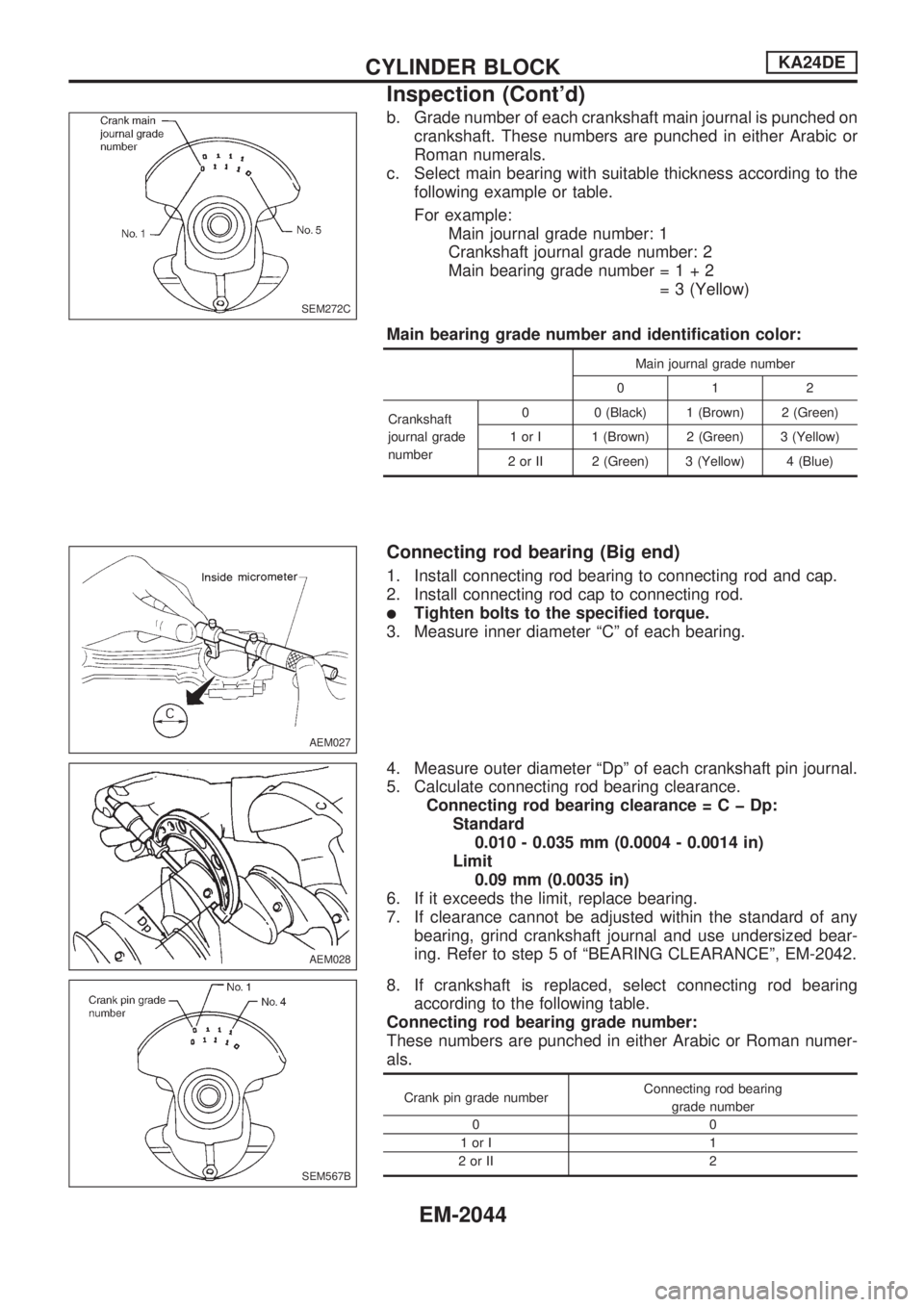
b. Grade number of each crankshaft main journal is punched on
crankshaft. These numbers are punched in either Arabic or
Roman numerals.
c. Select main bearing with suitable thickness according to the
following example or table.
For example:
Main journal grade number: 1
Crankshaft journal grade number: 2
Main bearing grade number=1+2
= 3 (Yellow)
Main bearing grade number and identification color:
Main journal grade number
012
Crankshaft
journal grade
number0 0 (Black) 1 (Brown) 2 (Green)
1 or I 1 (Brown) 2 (Green) 3 (Yellow)
2 or II 2 (Green) 3 (Yellow) 4 (Blue)
Connecting rod bearing (Big end)
1. Install connecting rod bearing to connecting rod and cap.
2. Install connecting rod cap to connecting rod.
lTighten bolts to the specified torque.
3. Measure inner diameter ªCº of each bearing.
4. Measure outer diameter ªDpº of each crankshaft pin journal.
5. Calculate connecting rod bearing clearance.
Connecting rod bearing clearance=CþDp:
Standard
0.010 - 0.035 mm (0.0004 - 0.0014 in)
Limit
0.09 mm (0.0035 in)
6. If it exceeds the limit, replace bearing.
7. If clearance cannot be adjusted within the standard of any
bearing, grind crankshaft journal and use undersized bear-
ing. Refer to step 5 of ªBEARING CLEARANCEº, EM-2042.
8. If crankshaft is replaced, select connecting rod bearing
according to the following table.
Connecting rod bearing grade number:
These numbers are punched in either Arabic or Roman numer-
als.
Crank pin grade numberConnecting rod bearing
grade number
00
1orI 1
2orII 2
SEM272C
AEM027
AEM028
SEM567B
CYLINDER BLOCKKA24DE
Inspection (Cont'd)
EM-2044
Page 473 of 666
Method B (Using plastigage)
CAUTION:
lDo not turn crankshaft or connecting rod while plasti-
gage is being inserted.
lWhen bearing clearance exceeds the specified limit,
ensure that the proper bearing has been installed. Then
if excessive bearing clearance exists, use a thicker main
bearing or undersized bearing so that the specified bear-
ing clearance is obtained.
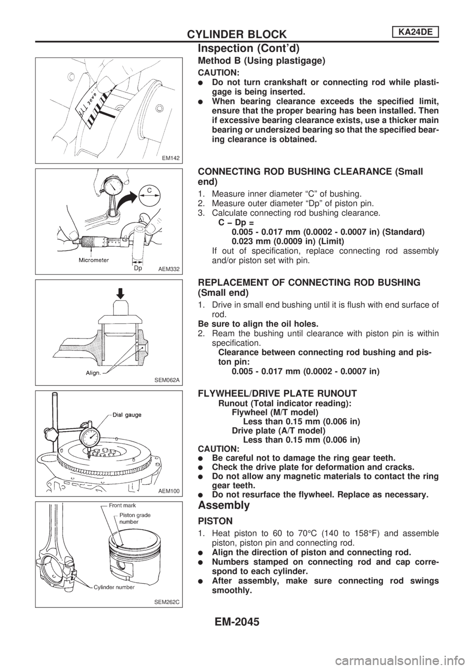
CONNECTING ROD BUSHING CLEARANCE (Small
end)
1. Measure inner diameter ªCº of bushing.
2. Measure outer diameter ªDpº of piston pin.
3. Calculate connecting rod bushing clearance.
CþDp=
0.005 - 0.017 mm (0.0002 - 0.0007 in) (Standard)
0.023 mm (0.0009 in) (Limit)
If out of specification, replace connecting rod assembly
and/or piston set with pin.
REPLACEMENT OF CONNECTING ROD BUSHING
(Small end)
1. Drive in small end bushing until it is flush with end surface of
rod.
Be sure to align the oil holes.
2. Ream the bushing until clearance with piston pin is within
specification.
Clearance between connecting rod bushing and pis-
ton pin:
0.005 - 0.017 mm (0.0002 - 0.0007 in)
FLYWHEEL/DRIVE PLATE RUNOUT
Runout (Total indicator reading):
Flywheel (M/T model)
Less than 0.15 mm (0.006 in)
Drive plate (A/T model)
Less than 0.15 mm (0.006 in)
CAUTION:
lBe careful not to damage the ring gear teeth.
lCheck the drive plate for deformation and cracks.
lDo not allow any magnetic materials to contact the ring
gear teeth.
lDo not resurface the flywheel. Replace as necessary.
Assembly
PISTON
1. Heat piston to 60 to 70ÉC (140 to 158ÉF) and assemble
piston, piston pin and connecting rod.
lAlign the direction of piston and connecting rod.
lNumbers stamped on connecting rod and cap corre-
spond to each cylinder.
lAfter assembly, make sure connecting rod swings
smoothly.
EM142
AEM332
SEM062A
AEM100
SEM262C
CYLINDER BLOCKKA24DE
Inspection (Cont'd)
EM-2045
Page 474 of 666
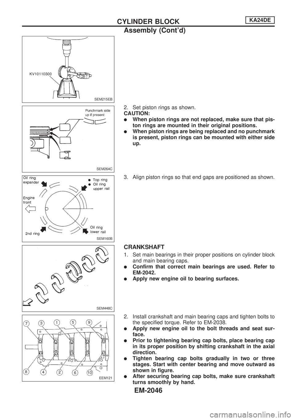
2. Set piston rings as shown.
CAUTION:
lWhen piston rings are not replaced, make sure that pis-
ton rings are mounted in their original positions.
lWhen piston rings are being replaced and no punchmark
is present, piston rings can be mounted with either side
up.
3. Align piston rings so that end gaps are positioned as shown.
CRANKSHAFT
1. Set main bearings in their proper positions on cylinder block
and main bearing caps.
lConfirm that correct main bearings are used. Refer to
EM-2042.
lApply new engine oil to bearing surfaces.
2. Install crankshaft and main bearing caps and tighten bolts to
the specified torque. Refer to EM-2038.
lApply new engine oil to the bolt threads and seat sur-
face.
lPrior to tightening bearing cap bolts, place bearing cap
in its proper position by shifting crankshaft in the axial
direction.
lTighten bearing cap bolts gradually in two or three
stages. Start with center bearing and move outward as
shown in figure.
lAfter securing bearing cap bolts, make sure crankshaft
turns smoothly by hand.
SEM215EB
SEM264C
SEM160B
SEM448C
EEM121
CYLINDER BLOCKKA24DE
Assembly (Cont'd)
EM-2046
Page 475 of 666
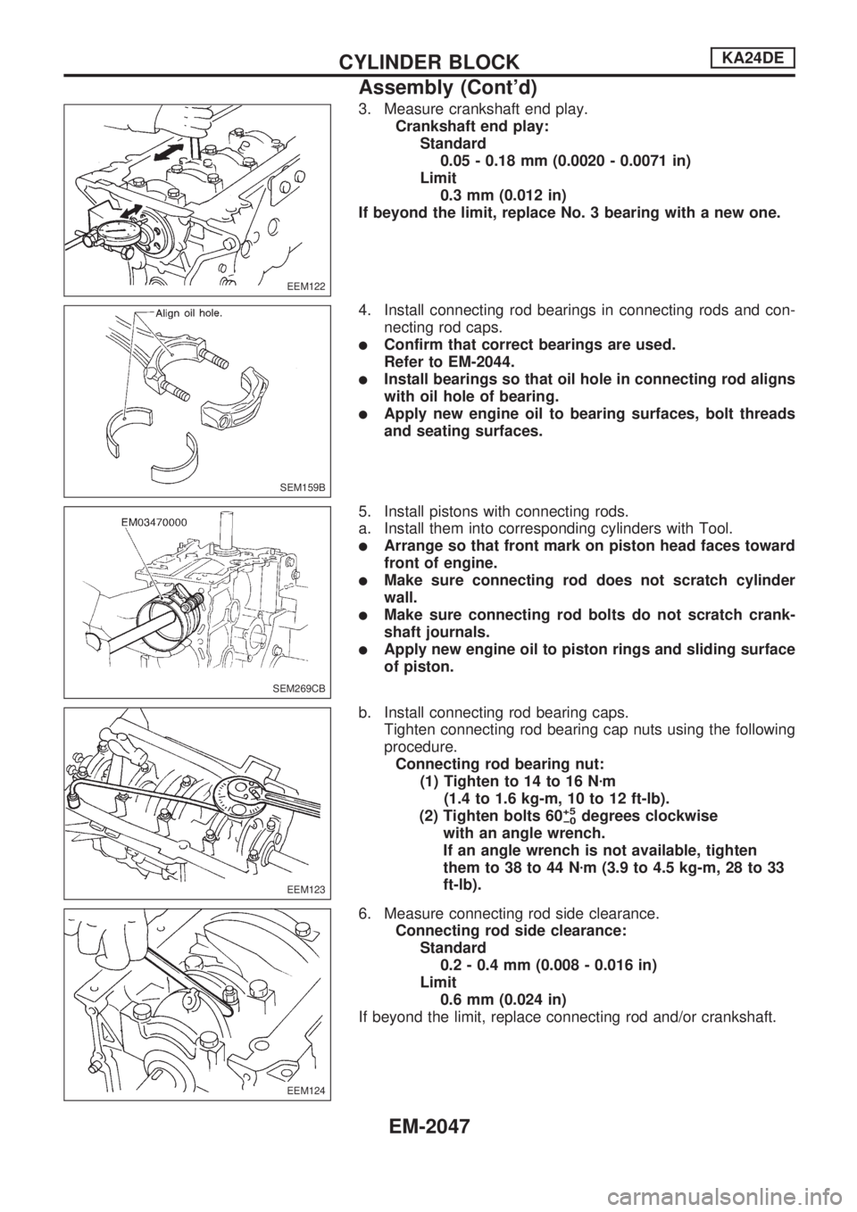
3. Measure crankshaft end play.
Crankshaft end play:
Standard
0.05 - 0.18 mm (0.0020 - 0.0071 in)
Limit
0.3 mm (0.012 in)
If beyond the limit, replace No. 3 bearing with a new one.
4. Install connecting rod bearings in connecting rods and con-
necting rod caps.
lConfirm that correct bearings are used.
Refer to EM-2044.
lInstall bearings so that oil hole in connecting rod aligns
with oil hole of bearing.
lApply new engine oil to bearing surfaces, bolt threads
and seating surfaces.
5. Install pistons with connecting rods.
a. Install them into corresponding cylinders with Tool.
lArrange so that front mark on piston head faces toward
front of engine.
lMake sure connecting rod does not scratch cylinder
wall.
lMake sure connecting rod bolts do not scratch crank-
shaft journals.
lApply new engine oil to piston rings and sliding surface
of piston.
b. Install connecting rod bearing caps.
Tighten connecting rod bearing cap nuts using the following
procedure.
Connecting rod bearing nut:
(1) Tighten to 14 to 16 Nzm
(1.4 to 1.6 kg-m, 10 to 12 ft-lb).
(2) Tighten bolts 60
+5
þ0degrees clockwise
with an angle wrench.
If an angle wrench is not available, tighten
them to 38 to 44 Nzm (3.9 to 4.5 kg-m, 28 to 33
ft-lb).
6. Measure connecting rod side clearance.
Connecting rod side clearance:
Standard
0.2 - 0.4 mm (0.008 - 0.016 in)
Limit
0.6 mm (0.024 in)
If beyond the limit, replace connecting rod and/or crankshaft.
EEM122
SEM159B
SEM269CB
EEM123
EEM124
CYLINDER BLOCKKA24DE
Assembly (Cont'd)
EM-2047
Page 480 of 666
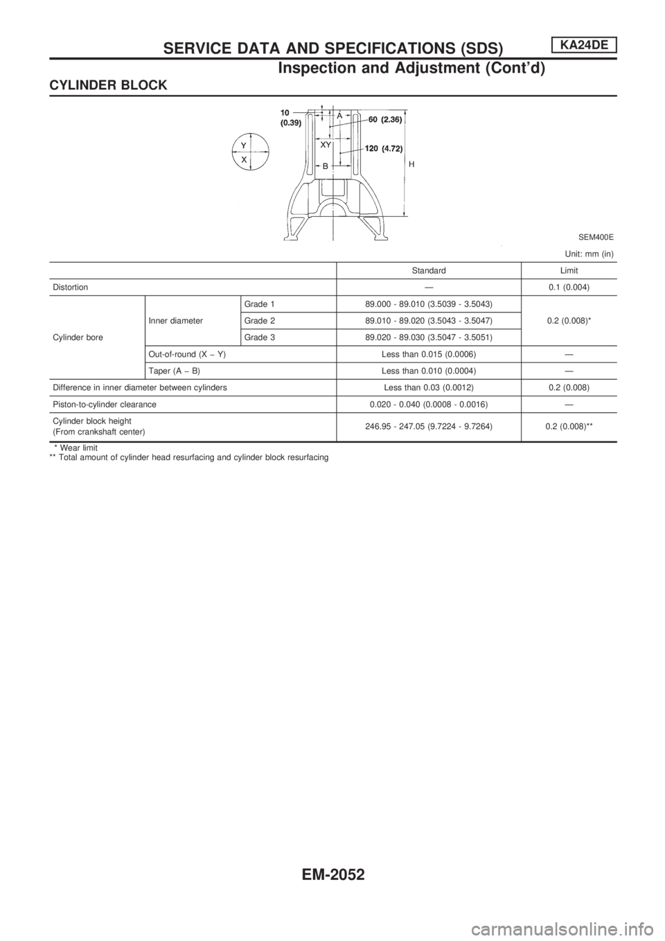
CYLINDER BLOCK
SEM400E
Unit: mm (in)
Standard Limit
DistortionÐ 0.1 (0.004)
Cylinder boreInner diameterGrade 1 89.000 - 89.010 (3.5039 - 3.5043)
0.2 (0.008)* Grade 2 89.010 - 89.020 (3.5043 - 3.5047)
Grade 3 89.020 - 89.030 (3.5047 - 3.5051)
Out-of-round (X þ Y) Less than 0.015 (0.0006) Ð
Taper (A þ B) Less than 0.010 (0.0004) Ð
Difference in inner diameter between cylinders Less than 0.03 (0.0012) 0.2 (0.008)
Piston-to-cylinder clearance 0.020 - 0.040 (0.0008 - 0.0016) Ð
Cylinder block height
(From crankshaft center)246.95 - 247.05 (9.7224 - 9.7264) 0.2 (0.008)**
* Wear limit
** Total amount of cylinder head resurfacing and cylinder block resurfacing
SERVICE DATA AND SPECIFICATIONS (SDS)KA24DE
Inspection and Adjustment (Cont'd)
EM-2052
Page 481 of 666
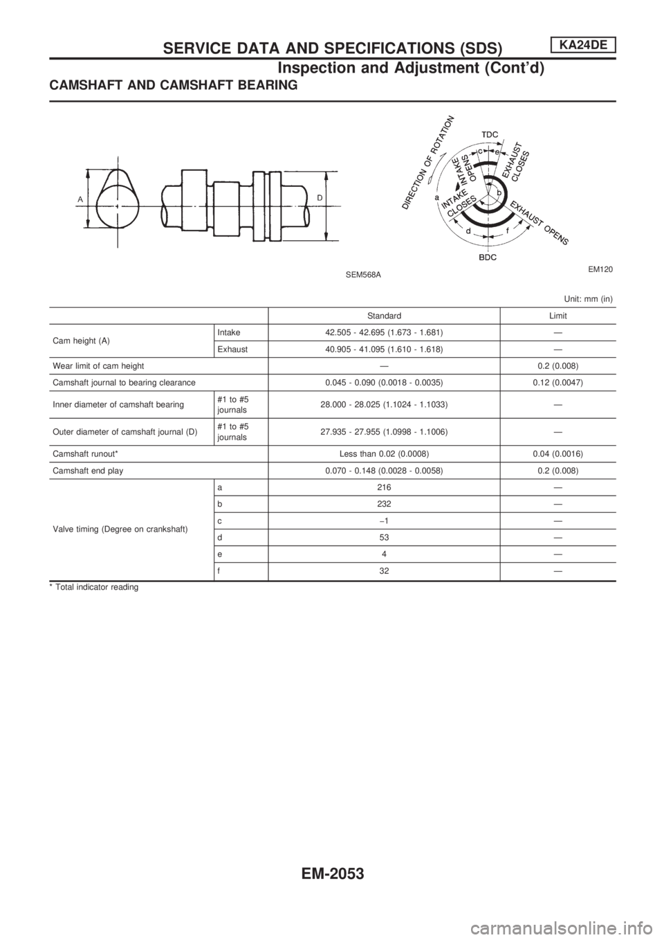
CAMSHAFT AND CAMSHAFT BEARING
SEM568AEM120
Unit: mm (in)
Standard Limit
Cam height (A)Intake 42.505 - 42.695 (1.673 - 1.681) Ð
Exhaust 40.905 - 41.095 (1.610 - 1.618) Ð
Wear limit of cam height Ð 0.2 (0.008)
Camshaft journal to bearing clearance 0.045 - 0.090 (0.0018 - 0.0035) 0.12 (0.0047)
Inner diameter of camshaft bearing#1 to #5
journals28.000 - 28.025 (1.1024 - 1.1033) Ð
Outer diameter of camshaft journal (D)#1 to #5
journals27.935 - 27.955 (1.0998 - 1.1006) Ð
Camshaft runout* Less than 0.02 (0.0008) 0.04 (0.0016)
Camshaft end play 0.070 - 0.148 (0.0028 - 0.0058) 0.2 (0.008)
Valve timing (Degree on crankshaft)a 216 Ð
b 232 Ð
cþ1 Ð
d53 Ð
e4 Ð
f32 Ð
* Total indicator reading
SERVICE DATA AND SPECIFICATIONS (SDS)KA24DE
Inspection and Adjustment (Cont'd)
EM-2053
Page 483 of 666
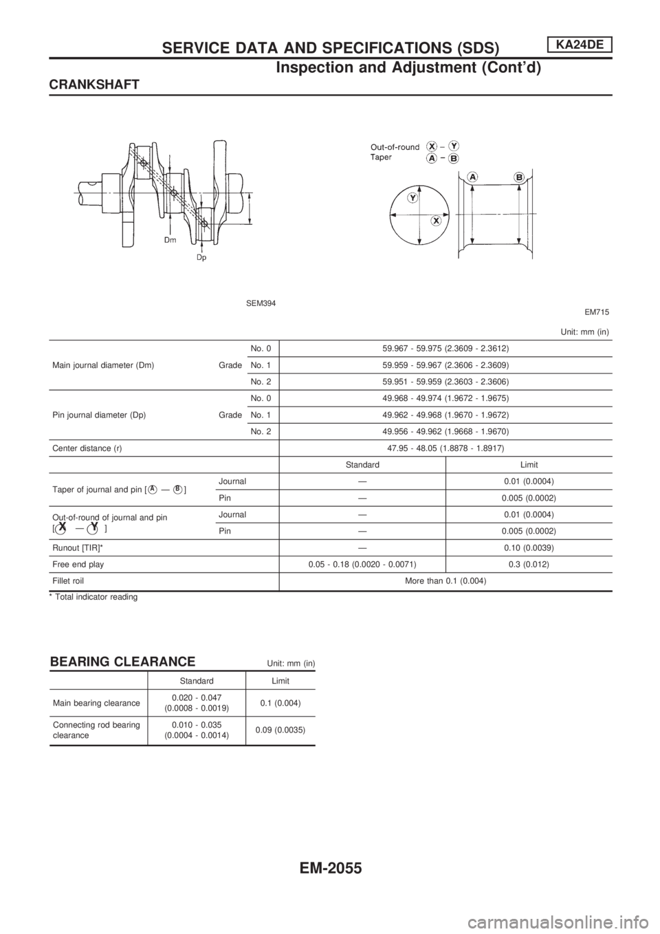
CRANKSHAFT
SEM394EM715
Unit: mm (in)
Main journal diameter (Dm) GradeNo. 0 59.967 - 59.975 (2.3609 - 2.3612)
No. 1 59.959 - 59.967 (2.3606 - 2.3609)
No. 2 59.951 - 59.959 (2.3603 - 2.3606)
Pin journal diameter (Dp) GradeNo. 0 49.968 - 49.974 (1.9672 - 1.9675)
No. 1 49.962 - 49.968 (1.9670 - 1.9672)
No. 2 49.956 - 49.962 (1.9668 - 1.9670)
Center distance (r) 47.95 - 48.05 (1.8878 - 1.8917)
Standard Limit
Taper of journal and pin [
VAÐVB]Journal Ð 0.01 (0.0004)
Pin Ð 0.005 (0.0002)
Out-of-round of journal and pin
[
jXÐjY]Journal Ð 0.01 (0.0004)
Pin Ð 0.005 (0.0002)
Runout [TIR]* Ð 0.10 (0.0039)
Free end play 0.05 - 0.18 (0.0020 - 0.0071) 0.3 (0.012)
Fillet roilMore than 0.1 (0.004)
* Total indicator reading
BEARING CLEARANCEUnit: mm (in)
Standard Limit
Main bearing clearance0.020 - 0.047
(0.0008 - 0.0019)0.1 (0.004)
Connecting rod bearing
clearance0.010 - 0.035
(0.0004 - 0.0014)0.09 (0.0035)
SERVICE DATA AND SPECIFICATIONS (SDS)KA24DE
Inspection and Adjustment (Cont'd)
EM-2055
Page 590 of 666
A
A/C harness layout (auto A/C)..................HA-2026
A/C operational check...............................HA-2041
A/C relay .........................................HA-2021, 2073
A/C self-diagnoses (auto A/C) ..................HA-2034
A/C switch .................................................HA-2021
A/C system description (auto A/C) ...........HA-2023
A/C trouble diagnoses (manual A/C) ........HA-2003
A/C, A - Wiring diagram............................HA-2028
A/C, M - Wiring diagram ...........................HA-2005
AAC/V - Wiring diagram ...........................EC-2011
Air bag.......................................................RS-2004
Air bag disposal ........................................RS-2012
Air flow meter - See Mass air flow
sensor....................................................EC-2008
Air mix door control linkage
adjustment .............................................HA-2057
Air mix door motor ....................................HA-2057
Alternator ...................................................EL-2016
Ambient sensor .........................................HA-2080
Antenna .....................................................EL-2103
Anti-lock brake system - Wiring
diagram .......................................BR-2004, 2007
Aspirator motor .........................................HA-2084
Audio and A/C control removal and
installation - See Instrument panel........BT-2004
Automatic amplifier .........................HA-2032, 2045
Auxiliary air control (AAC) valve ...............EC-2011
B
Back-up lamp.............................................EL-2035
Back-up lamp switch (M/T) .......................MT-2002
Baulk ring (M/T) ........................................MT-2003
C
Camshaft position sensor (CMPS) ...........EC-2007
Center bearing assembly (propeller
shaft) .....................................................PD-2006
CHARGE - Wiring diagram .......................EL-2013
Charging system........................................EL-2013
CIGAR - Wiring diagram ...........................EL-2094
Cigarette lighter .........................................EL-2094
Clock ..........................................................EL-2095
CLOCK - Wiring diagram ..........................EL-2095
CMPS - Wiring diagram ............................EC-2007
Collision diagnosis ....................................RS-2039
Combination meter ....................................EL-2049
Combination meter removal and instal-
lation - See Instrument panel ................BT-2004
Combination switch ...................................EL-2017
Control units (terminal arrangement) ........EL-2176
Cooling fan control system........................LC-2002
Counter gear (M/T) ...................................MT-2003
Coupling sleeve (M/T) ..............................MT-2003Crank angle sensor built into distribu-
tor - See Camshaft position sensor ......EC-2007
Crankshaft position sensor (POS) ............EC-2007
Crankshaft position sensor (REF) ............EC-2007
Cylinder head ...........................................EM-2003
D
Daytime light system .................................EL-2022
DEF - Wiring diagram................................EL-2096
Diagnosis sensor unit ...............................RS-2007
Differential carrier assembly .....................PD-2008
Dim-dip lamp system .................................EL-2025
Dimensions.................................................GI-2007
Door, front .................................................BT-2003
E
ECCS relay ...............................................EC-2005
EGR - Wiring diagram ..............................EC-2027
EGRC/V - Wiring diagram ........................EC-2013
Engine control circuit diagram ..................EC-2004
Engine outer component parts .................EM-2002
EVAP canister purge control solenoid
valve ......................................................EC-2013
F
F/HEAT - Wiring diagram .........................EC-2033
F/PUMP - Wiring diagram.........................EC-2015
Fan control amp. .......................................HA-2064
Fan switch .................................................HA-2021
FICD - Wiring diagram....................EC-2018, 2034
Fog lamp, rear ...........................................EL-2036
Fork rod (M/T)...........................................MT-2006
Front door ..................................................BT-2003
Front passenger air bag ...........................RS-2004
Front suspension .......................................FA-2002
Front wiper.................................................EL-2086
Fuel pump .................................................EC-2015
Fuel pump relay ........................................EC-2015
Fuse block .................................................EL-2175
G
Gauges ......................................................EL-2049
Gear components (M/T) ...........................MT-2003
Ground clearance.......................................GI-2007
H
H/AIM - Wiring diagram .............................EL-2028
H/LAMP - Wiring diagram .........................EL-2018
H02S - Wiring diagram .............................EC-2010
ALPHABETICAL INDEX
IDX-2002