Page 557 of 666

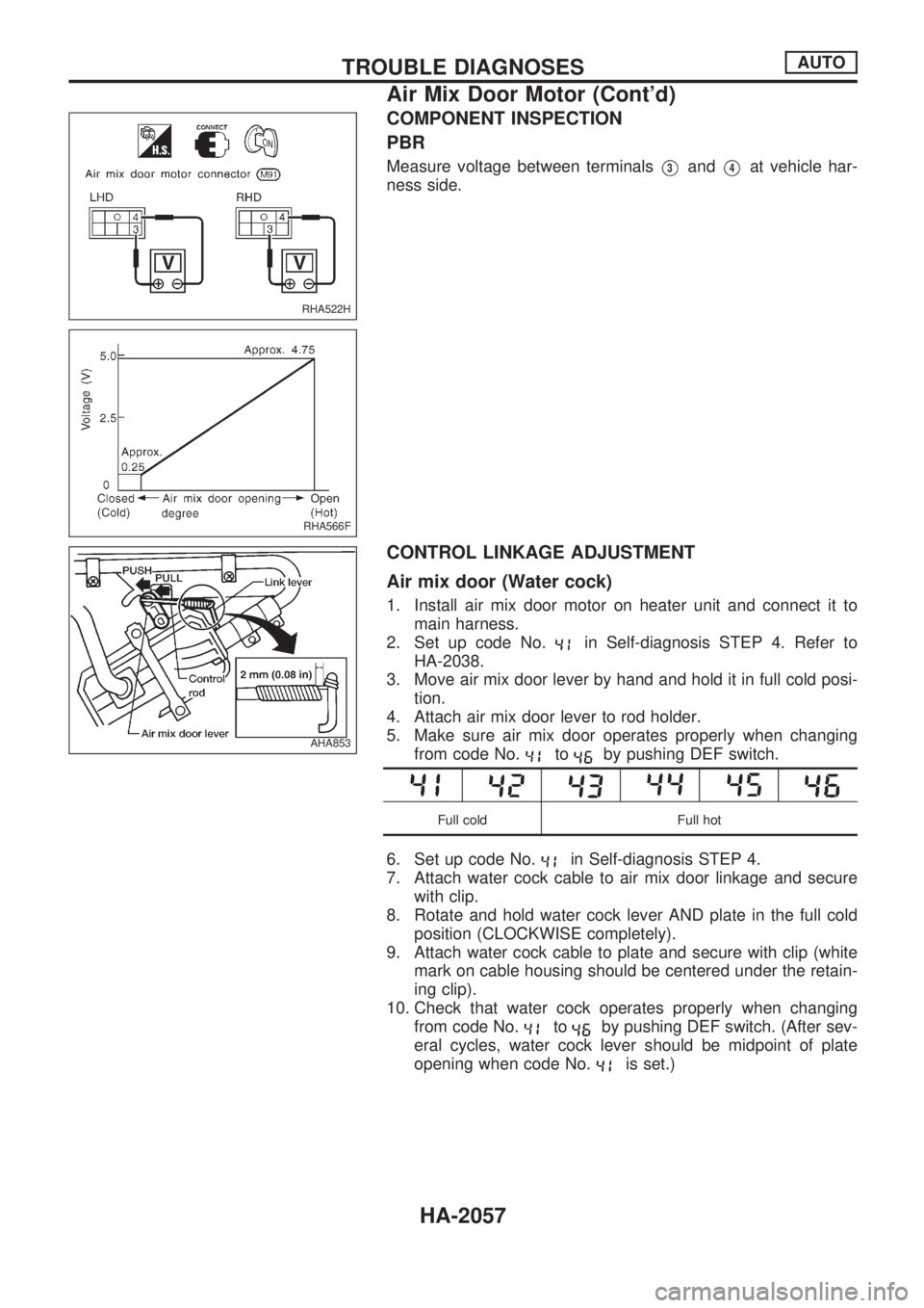
COMPONENT INSPECTION
PBR
Measure voltage between terminalsV3andV4at vehicle har-
ness side.
CONTROL LINKAGE ADJUSTMENT
Air mix door (Water cock)
1. Install air mix door motor on heater unit and connect it to
main harness.
2. Set up code No.
in Self-diagnosis STEP 4. Refer to
HA-2038.
3. Move air mix door lever by hand and hold it in full cold posi-
tion.
4. Attach air mix door lever to rod holder.
5. Make sure air mix door operates properly when changing
from code No.
toby pushing DEF switch.
Full cold Full hot
6. Set up code No.in Self-diagnosis STEP 4.
7. Attach water cock cable to air mix door linkage and secure
with clip.
8. Rotate and hold water cock lever AND plate in the full cold
position (CLOCKWISE completely).
9. Attach water cock cable to plate and secure with clip (white
mark on cable housing should be centered under the retain-
ing clip).
10. Check that water cock operates properly when changing
from code No.
toby pushing DEF switch. (After sev-
eral cycles, water cock lever should be midpoint of plate
opening when code No.
is set.)
RHA522H
RHA566F
AHA853
TROUBLE DIAGNOSESAUTO
Air Mix Door Motor (Cont'd)
HA-2057
Page 612 of 666
Disassembly
CENTER BEARING
1. Place matching marks on flanges, then separate 2nd tube
from 1st tube.
2. Place matching marks on the flange and shaft.
3. Secure the flange yoke with a vice and remove the lock nut.
4. Remove flange yoke using puller.
5. Remove center bearing using Tool and press.
Tool number: ST30031000
Assembly
CENTER BEARING
lWhen installing center bearing, position the ªFº mark on cen-
ter bearing toward front of vehicle.
lApply a coat of multi-purpose lithium grease containing
molybdenum disulfide to the end face of the center bear-
ing and both sides of the washer.
lStake the nut. Always use new one.
lAlign match marks when assembling tubes.
SPD513A
SPD514A
SPD113
SPD114
PROPELLER SHAFTPropeller shaft
PD-2006
Page 635 of 666

Deployment of passenger air bag module (outside of
vehicle)
1. Make an 8.5 mm (0.335 in) diameter hole in passenger air
bag bracket (SST: KV99105300) at the position shown in
figure at left.
2. Firmly secure passenger air bag bracket (SST: KV99105300)
in a vise.
3. Match the two holes in passenger air bag bracket (held in
vise) and passenger air bag module and fix them with two
bolts [M8 x 25 - 30 mm (0.98 - 1.18 in)].
CAUTION:
If a gap exists between passenger air bag module and pas-
senger air bag bracket, use a piece of wood inserted in the
gap to stabilize the air bag module.
4. Connect deployment tool adapter (SST: KV99108300) to
deployment tool (SST: KV99106400) connector and connec-
tor on either side of air bag module.
5. Connect red clip of deployment tool to battery positive termi-
nal and black clip to negative terminal.
6. The lamp on the right side of the tool, marked ``deployment
tool power'', should glow green, not red.
7. Press the button on the deployment tool. The left side lamp
on the tool, marked ``air bag connector voltage'', will illumi-
nate and the air bag module will deploy.
CAUTION:
lWhen deploying the air bag module, do not stand on the
deploying side.
lStand at least 5 m (16 ft) away from the air bag module.
SRS732
SRS145
SRS686-A
SRS687-A
SRS020-A
SUPPLEMENTAL RESTRAINT SYSTEM (SRS)
Disposal of Air Bag Module (Cont'd)
RS-2013
Page 637 of 666

Trouble Diagnoses Introduction
CAUTION:
lDo not use electrical test equipment to check SRS harness connectors unless instructed to in
this Service Manual. SRS wiring harnesses can be identified by yellow harness protector or yel-
low insulation tape before the harness connectors.
lDo not attempt to repair, splice or modify the SRS wiring harness. If the harness is damaged,
replace it with a new one.
lKeep ground portion clean.
DIAGNOSIS FUNCTION
The SRS self-diagnosis results can be read by using ``AIR BAG'' warning lamp and/or CONSULT. The
reading of these results is accomplished using one of two modes Ð ``User mode'' and ``Diagnosis mode''.
The User mode is exclusively prepared for the customer (driver). This mode warns the driver of a system
malfunction through the operation of the ``AIR BAG'' warning lamp.
The Diagnosis mode allows the technician to locate and inspect the malfunctioning part.
The mode applications for the ``AIR BAG'' warning lamp and CONSULT are as follows:
User mode Diagnosis mode Display type
``AIR BAG'' warning lamp X X ON-OFF operation
DIAGNOSIS MODE FOR CONSULT
l``SELF-DIAG [CURRENT]''
A current Self-diagnosis result (also indicated by the warning lamp flashes in the Diagnosis mode) is
displayed on the CONSULT screen in real time. This refers to a malfunctioning part requiring repairs.
l``SELF-DIAG [PAST]''
Diagnosis results previously stored in the memory are displayed on the CONSULT screen. The stored
results are not erased until memory erasing is executed.
l``TROUBLE DIAG RECORD''
With TROUBLE DIAG RECORD, diagnosis results previously erased by a reset operation can be dis-
played on the CONSULT screen.
l``ECU DISCRIMINATED NO.''
The diagnosis sensor unit for each vehicle model is assigned with its own, individual classification number.
This number will be displayed on the CONSULT screen, as shown at left. When replacing the diagnosis
sensor unit, refer to the part number for the compatibility. After installation, replacement with a correct unit
can be checked by confirming this classification number on the CONSULT screen. The diagnosis sensor
unit classification number varies depending on SRS configuration.
For NISSAN MODEL D22, the diagnosis sensor unit classification numbers assigned are as follows.
MODEL ECU DISCRIMINATED NO.
Single air bag 5A0B
Dual air bag 5A0A
TROUBLE DIAGNOSES Ð Supplemental Restraint System (SRS)
RS-2015
Page 662 of 666
Part Side is activated SRS is NOT activated
Instrument panel 1. When passenger air bag inflates, check the following points for bending, deformities or cracks.
lOpening portion for passenger air bag
SRS738
lPassenger air bag module brackets
SRS739
lThe portions securing the instrument panel
SRS740
2. If no damage is found, reinstall the instrument panel.
3. If damagedÐREPLACE the instrument panel with bolts.
COLLISION DIAGNOSIS
RS-2040