Page 26 of 558

11-1
ENGINE
CONTENTS
GENERAL INFORMATION 2. . . . . . . . . . . . . . . .
SPECIFICATIONS 3. . . . . . . . . . . . . . . . . . . . . . . .
Service Specifications 3. . . . . . . . . . . . . . . . . . . . . .
Torque Specifications 5. . . . . . . . . . . . . . . . . . . . . .
New Tightening Method by Use of Bolts
to Be Tightened in Plastic Area 9. . . . . . . . . . . .
Sealants 9. . . . . . . . . . . . . . . . . . . . . . . . . . . . . . . . . .
Form-In-Place Gasket 10. . . . . . . . . . . . . . . . . . . .
SPECIAL TOOLS 11. . . . . . . . . . . . . . . . . . . . . . .
ALTERNATOR AND IGNITION SYSTEM 14.
TIMING BELT 15. . . . . . . . . . . . . . . . . . . . . . . . .
FUEL AND EMISSION CONTROL PARTS 27
SECONDARY AIR SYSTEM AND INTAKE
MANIFOLD 29. . . . . . . . . . . . . . . . . . . . . . . . . . . . EXHAUST MANIFOLD 31. . . . . . . . . . . . . . . . .
WATER PUMP AND WATER HOSE 34. . . . .
ROCKER ARMS AND CAMSHAFT 37. . . . . .
CYLINDER HEAD AND VALVES 43. . . . . . . .
FRONT CASE, COUNTERBALANCE
SHAFT AND OIL PAN 51. . . . . . . . . . . . . . . . .
PISTON AND CONNECTING ROD 59. . . . . .
CRANKSHAFT AND FLYWHEEL 67. . . . . . . .
THROTTLE BODY 73. . . . . . . . . . . . . . . . . . . . .
TURBOCHARGER 75. . . . . . . . . . . . . . . . . . . . .
ALTERNATOR 79. . . . . . . . . . . . . . . . . . . . . . . . .
STARTER MOTOR 83. . . . . . . . . . . . . . . . . . . . .
Page 28 of 558

ENGINE – Specifications11-3
SPECIFICATIONS
SERVICE SPECIFICATIONS
ItemsStandard valueLimit
Timing belt
Auto-tensioner rod projection length mm12–
Auto-tensioner rod pushed-in amount [when pushed with a force of 98
– 196 N] mm1.0 or less–
Rocker arms and camshaft
Camshaft cam height mmIntake35.7935.29
Exhaust35.4934.99
Camshaft journal outer diameter mm26–
Cylinder head and valves
Cylinder head flatness of gasket surface mmLess than 0.050.2
Cylinder head grinding limit of gasket surface mm
Total resurfacing depth of both cylinder head and cylinder block–0.2
Cylinder head overall height mm131.9 – 132.1–
Cylinder head bolt shank length mm–Maximum 99.4
Valve thickness of valve head (margin) mmIntake1.00.5
Exhaust1.51.0
Overall valve length mmIntake109.5109.0
Exhaust109.7109.2
Valve thickness to valve guide clearance
mm
Intake0.02 – 0.050.10
mmExhaust0.05 – 0.090.15
Valve face angle45° – 45.5°–
Valve spring free length mm48.347.3
Valve spring load/installed height N/mm294/40.0–
Valve spring out-of-squareness1.5° or lessMaximum 4°
Valve seat contact width mm0.9 – 1.3–
Valve guide inner diameter mm6.6–
Valve guide projection from cylinder head upper surface mm20.5–
Valve stem projection mmIntake49.2049.70
Exhaust48.4048.90
Oversize rework dimensions of valve guide
hole mm
0.05 O.S.12.05 – 12.07–
hole mm0.25 O.S.12.25 – 11.27–
0.50 O.S.12.50 – 12.52–
Page 34 of 558

ENGINE – Specifications11-9
NEW TIGHTENING METHOD – BY USE OF BOLTS TO BE TIGHTENED IN
PLASTIC AREA
A new type of bolts, to be tightened in plastic area, is currently used some parts of the engine. The
tightening method for the bolts is different from the conventional one. Be sure to observe the method
described in the text when tightening the bolts.
Service limits are provided for the bolts. Make sure that the service limits described in the text are strictly
observed.
�Areas where the bolts are in use:
(1) Cylinder head bolts
(2) Main bearing cap bolts
(3) Connecting rod cap bolts
�Tightening method
After tightening the bolts to the specified torque, tighten them another 90° or 180° (twice 90°). The
tightening method varies on different areas. Observe the tightening method described in the text.
SEALANTS
ItemSpecified sealantQuantity
Engine support bracket bolt3MTM AAD Part No. 8672 or equivalentAs required
Semi-circular packing3MTM AAD Part No. 8672 or equivalentAs required
Rocker cover3MTM AAD Part No. 8672 or equivalentAs required
Oil return pipe gasket3MTM AAD Part No. 8731 or equivalentAs required
Thermostat housingMitsubishi Genuine Part No. MD970389 or
equivalentAs required
Water outlet fittingMitsubishi Genuine Part No. MD970389 or
equivalentAs required
Engine coolant temperature gauge unit3MTM AAD Part No. 8672 or equivalentAs required
Engine coolant temperature sensor3MTM AAD Part No. 8731 or equivalentAs required
Cam position sensor supportMitsubishi Genuine Part No. MD970389 or
equivalentAs required
Oil pressure switch3MTM AAD Part No. 8672 or equivalentAs required
Oil panMitsubishi Genuine Part No. MD970389 or
equivalentAs required
Oil seal caseMitsubishi Genuine Part No. MD970389 or
equivalentAs required
Page 41 of 558

ENGINE – Timing Belt11-16
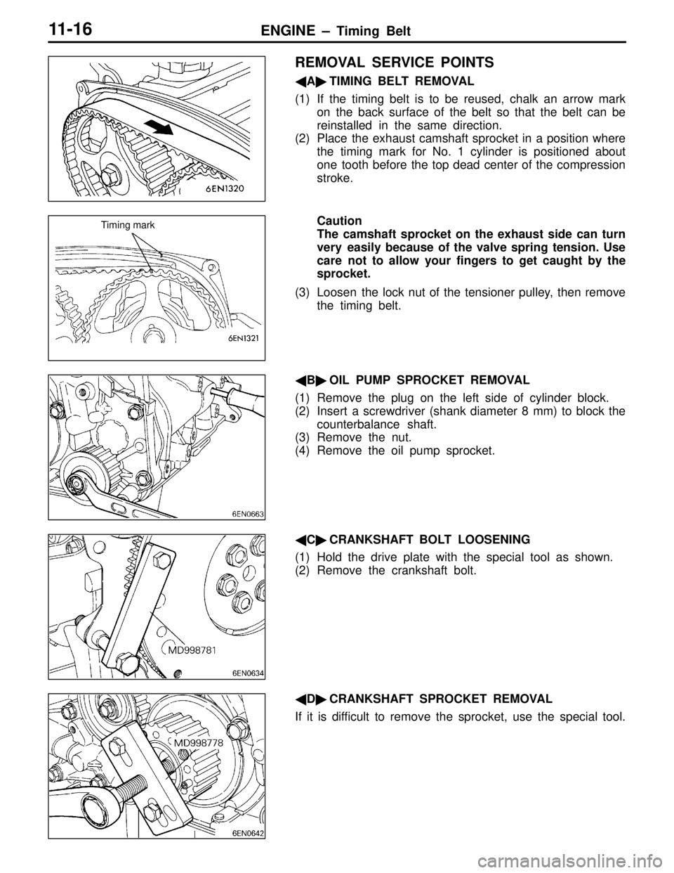
REMOVAL SERVICE POINTS
�A�TIMING BELT REMOVAL
(1) If the timing belt is to be reused, chalk an arrow mark
on the back surface of the belt so that the belt can be
reinstalled in the same direction.
(2) Place the exhaust camshaft sprocket in a position where
the timing mark for No. 1 cylinder is positioned about
one tooth before the top dead center of the compression
stroke.
Caution
The camshaft sprocket on the exhaust side can turn
very easily because of the valve spring tension. Use
care not to allow your fingers to get caught by the
sprocket.
(3) Loosen the lock nut of the tensioner pulley, then remove
the timing belt.
�B�OIL PUMP SPROCKET REMOVAL
(1) Remove the plug on the left side of cylinder block.
(2) Insert a screwdriver (shank diameter 8 mm) to block the
counterbalance shaft.
(3) Remove the nut.
(4) Remove the oil pump sprocket.
�C�CRANKSHAFT BOLT LOOSENING
(1) Hold the drive plate with the special tool as shown.
(2) Remove the crankshaft bolt.
�D�CRANKSHAFT SPROCKET REMOVAL
If it is difficult to remove the sprocket, use the special tool.
Timing mark
Page 42 of 558

ENGINE – Timing BeltENGINE – Timing Belt11-17
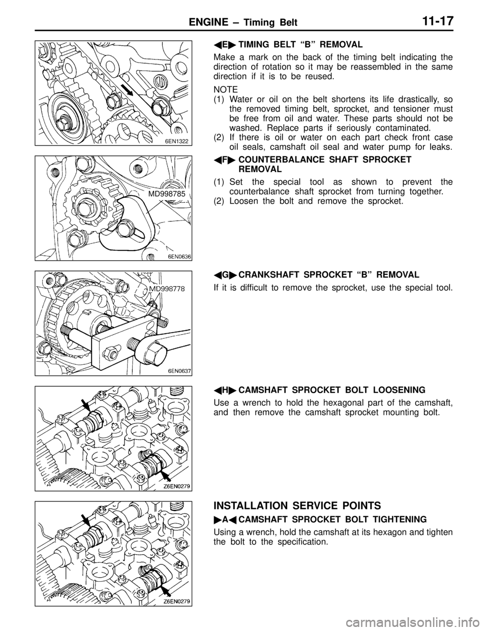
�E�TIMING BELT “B” REMOVAL
Make a mark on the back of the timing belt indicating the
direction of rotation so it may be reassembled in the same
direction if it is to be reused.
NOTE
(1) Water or oil on the belt shortens its life drastically, so
the removed timing belt, sprocket, and tensioner must
be free from oil and water. These parts should not be
washed. Replace parts if seriously contaminated.
(2) If there is oil or water on each part check front case
oil seals, camshaft oil seal and water pump for leaks.
�F�COUNTERBALANCE SHAFT SPROCKET
REMOVAL
(1) Set the special tool as shown to prevent the
counterbalance shaft sprocket from turning together.
(2) Loosen the bolt and remove the sprocket.
�G�CRANKSHAFT SPROCKET “B” REMOVAL
If it is difficult to remove the sprocket, use the special tool.
�H�CAMSHAFT SPROCKET BOLT LOOSENING
Use a wrench to hold the hexagonal part of the camshaft,
and then remove the camshaft sprocket mounting bolt.
INSTALLATION SERVICE POINTS
�A�CAMSHAFT SPROCKET BOLT TIGHTENING
Using a wrench, hold the camshaft at its hexagon and tighten
the bolt to the specification.
6EN1322
MD998785
Page 53 of 558
ENGINE – Fuel and Emission Control Parts11-28
INSTALLATION SERVICE POINTS
�A�INJECTORS INSTALLATION
(1) Before installing an injector, the rubber O-ring must be
lubricated with a drop of clean engine oil to aid in
installation.
(2) Install injector top end. Be careful not to damage O-ring
during installation.
�B�FUEL PRESSURE REGULATOR INSTALLATION
(1) Apply a small amount of new engine oil to the O-ring.
Insert the fuel pressure regulator into the delivery pipe
being careful not to damage the O-ring.
Caution
Be sure not to let engine oil get into the delivery
pipe.
(2) Check that the fuel pressure regulator turns smoothly.
If it does not turn smoothly, the O-ring may be trapped.
Remove the fuel pressure regulator and check the O-ring
for damage, and then re-insert it into the delivery pipe
and check once again.
�C�GASKET INSTALLATION
Position the projection as shown in the illustration.
1EN0388
Grommet
O-ring
Projection
Page 55 of 558
ENGINE – Secondary Air System and Intake Manifold11-30
INSTALLATION SERVICE POINTS
�A�AIR CONTROL VALVE BRACKET INSTALLATION
(1) Attach the air control valve bracket and the engine hanger
to the intake manifold using bolts and nuts with which
the intake manifold is also installed to the engine.
(2) Tighten the bolts and nuts to the specified torque in the
sequence given in the illustration.
�B�AIR PIPE ASSEMBLY INSTALLATION
(1) Install the air pipe assembly to the exhaust manifold and
to the air control valve and secure it provisionally by
tightening the fasteners handtight.
(2) Tighten the fasteners to the specified torque in the
sequence given in the illustration.
(3)
(2) (1)
(3)
(2)(1)(4)
Page 57 of 558
ENGINE – Exhaust Manifold11-32
INSTALLATION SERVICE POINTS
�A�EXHAUST MANIFOLD INSTALLATION
Tighten the exhaust manifold mounting nuts to the specified
torque in the sequence given in the illustration.
�B�GASKET / OIL RETURN GASKET INSTALLATION
EVOLUTION IV AND V
Install the gasket with the silicon-printed side toward the oil
pan and with the tabbed end directed as shown.
EVOLUTION VI
(1) Install the gasket with the tabbed end directed as shown.
(2) Apply sealant to both sides of the oil return pipe gasket
and leave it for 20 minutes to dry before installing. Tighten
the mounting bolts to the specified torque.
Specified sealant:
3M
TM AAD Part No. 8731 or equivalent
NOTE
If mounting bolts with head mark 7 have been used,
be sure to replace them with bolts having head mark
10.
1234 5 6
789
Timing belt side
Oil pan
Oil return
pipe gasket Silicon print
Timing belt side
Oil pan
Oil return
pipe gasket
Oil pan
Oil return
pipe
Gasket