Page 85 of 558
ENGINE – Piston and Connecting Rod11-60
REMOVAL SERVICE POINTS
�A�CONNECTING ROD CAP REMOVAL
(1) Mark the cylinder number on the side of the connecting
rod big end for correct reassembly.
(2) Keep the removed connecting rods, caps, and bearings
in order according to the cylinder number.
�B�PISTON PIN REMOVAL
(1) Insert the special tool, Push Rod, into the piston from
the side on which the front mark is stamped in the piston
head, and attach the guide C to the push rod end.
(2) Place the piston and connecting rod assembly on the
special tool, Piston Pin Setting Base, with the front mark
facing upward.
(3) Using a press, remove the piston pin.
NOTE
Keep the disassembled pistons, piston pins and
connecting rods in order according to the cylinder number.
Page 86 of 558
ENGINE – Piston and Connecting Rod11-61
INSTALLATION SERVICE POINTS
�A�PISTON PIN INSTALLATION
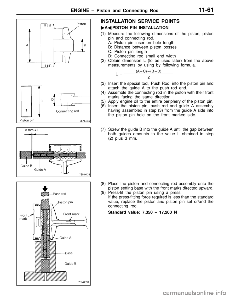
(1) Measure the following dimensions of the piston, piston
pin and connecting rod.
A: Piston pin insertion hole length
B: Distance between piston bosses
C: Piston pin length
D: Connecting rod small end width
(2) Obtain dimension L (to be used later) from the above
measurements by using by following formula.
L =
(A – C) – (B – D)
2
(3) Insert the special tool, Push Rod, into the piston pin and
attach the guide A to the push rod end.
(4) Assemble the connecting rod in the piston with their front
marks facing the same direction.
(5) Apply engine oil to the entire periphery of the piston pin.
(6) Insert the piston pin, push rod and guide A assembly
having assembled in step (3) from the guide A side into
the piston pin hole on the front marked side.
(7) Screw the guide B into the guide A until the gap between
both guides amounts to the value L obtained in step
(2) plus 3 mm.
(8) Place the piston and connecting rod assembly onto the
piston setting base with the front marks directed upward.
(9) Press-fit the piston pin using a press.
If the press-fitting force required is less than the standard
value, replace the piston and piston pin set or/and the
connecting rod.
Standard value: 7,350 – 17,200 N
3 mm + L
Page 88 of 558
ENGINE – Piston and Connecting Rod11-63
�C�PISTON RING NO. 2 / PISTON RING NO. 1
INSTALLATION
(1) Using piston ring expander, fit No. 2 and then No. 1 piston
ring into position.
NOTE
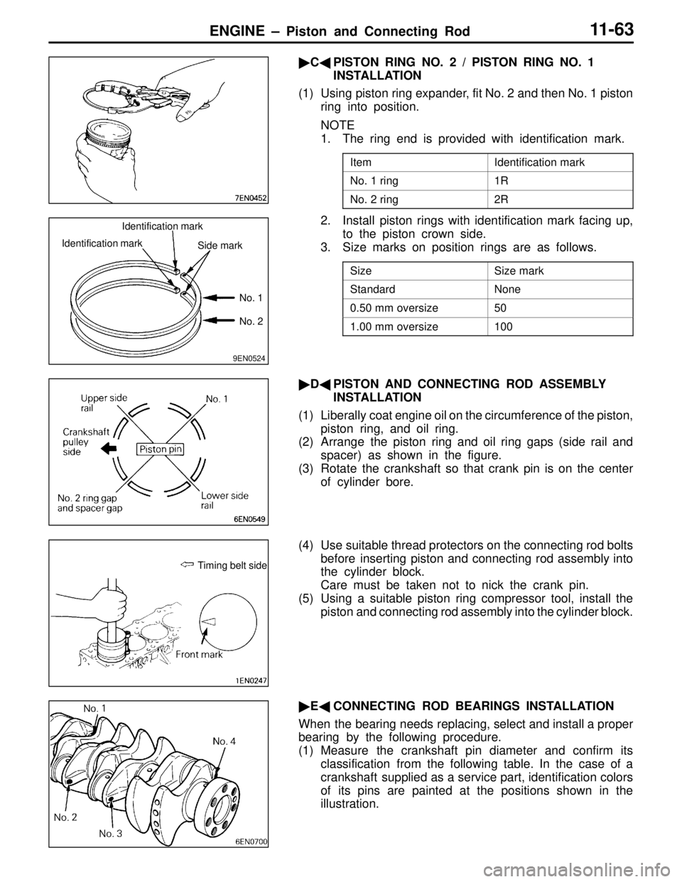
1. The ring end is provided with identification mark.
ItemIdentification mark
No. 1 ring1R
No. 2 ring2R
2. Install piston rings with identification mark facing up,
to the piston crown side.
3. Size marks on position rings are as follows.
SizeSize mark
StandardNone
0.50 mm oversize50
1.00 mm oversize100
�D�PISTON AND CONNECTING ROD ASSEMBLY
INSTALLATION
(1) Liberally coat engine oil on the circumference of the piston,
piston ring, and oil ring.
(2) Arrange the piston ring and oil ring gaps (side rail and
spacer) as shown in the figure.
(3) Rotate the crankshaft so that crank pin is on the center
of cylinder bore.
(4) Use suitable thread protectors on the connecting rod bolts
before inserting piston and connecting rod assembly into
the cylinder block.
Care must be taken not to nick the crank pin.
(5) Using a suitable piston ring compressor tool, install the
piston and connecting rod assembly into the cylinder block.
�E�CONNECTING ROD BEARINGS INSTALLATION
When the bearing needs replacing, select and install a proper
bearing by the following procedure.
(1) Measure the crankshaft pin diameter and confirm its
classification from the following table. In the case of a
crankshaft supplied as a service part, identification colors
of its pins are painted at the positions shown in the
illustration.
9EN0524
Identification mark
Identification mark
Side mark
No. 1
No. 2
Timing belt side
Page 89 of 558
ENGINE – Piston and Connecting Rod11-64
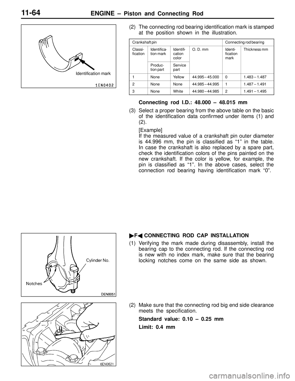
(2) The connecting rod bearing identification mark is stamped
at the position shown in the illustration.
Crankshaft pinConnecting rod bearing
Classi-
ficationIdentifica-
tion markIdentifi-
cation
colorO. D. mmIdenti-
fication
markThickness mm
Produc-
tion partService
part
1NoneYellow44.995 – 45.00001.483 – 1.487
2NoneNone44.985 – 44.99511.487 – 1.491
3NoneWhite44.980 – 44.98521.491 – 1.495
Connecting rod I.D.: 48.000 – 48.015 mm
(3) Select a proper bearing from the above table on the basic
of the identification data confirmed under items (1) and
(2).
[Example]
If the measured value of a crankshaft pin outer diameter
is 44.996 mm, the pin is classified as “1” in the table.
In case the crankshaft is also replaced by a spare part,
check the identification colors of the pins painted on the
new crankshaft. If the color is yellow, for example, the
pin is classified as “1”. In the above cases, select the
connection rod bearing having identification mark “0”.
�F�CONNECTING ROD CAP INSTALLATION
(1) Verifying the mark made during disassembly, install the
bearing cap to the connecting rod. If the connecting rod
is new with no index mark, make sure that the bearing
locking notches come on the same side as shown.
(2) Make sure that the connecting rod big end side clearance
meets the specification.
Standard value: 0.10 – 0.25 mm
Limit: 0.4 mm
Identification mark
Page 93 of 558
ENGINE – Crankshaft and Flywheel11-68
INSTALLATION SERVICE POINTS
�A�CRANKSHAFT THRUST BEARING INSTALLATION
(1) Install the two thrust bearing in the number 3 bearing
bore in the cylinder block. For easier installation, apply
engine oil to the bearings; this will help hold them in
position.
(2) The thrust bearings must be installed with their groove
side toward the crankshaft web.
�B�CRANKSHAFT BEARING INSTALLATION
(1) From the following table, select a bearing whose size
is appropriate for the crankshaft journal outside diameter.
Groove
Identification color of crankshaft journal
Bearing bore size
identification mark
Bearing bore
identification
mark
Cylinder inner
diameter size
mark
Rear face of
cylinder block Bottom of
cylinder block No. 1 No. 2No. 3
No. 4No. 5
Page 99 of 558
ENGINE – Throttle Body11-74
DISASSEMBLY SERVICE POINTS
�A�THROTTLE POSITION SENSOR AND IDLE AIR
CONTROL MOTOR REMOVAL
(1) Do not disassemble the sensor and motor.
(2) Do not immerse solvent to clean the sensor and motor.
Clean then with shop towel.
�B�THROTTLE BODY REMOVAL
(1) Do not remove the throttle body.
(2) Check if the vacuum port or passage is clogged. Use
compressed air to clean the vacuum passage.
REASSEMBLY SERVICE POINT
�A�THROTTLE POSITION SENSOR INSTALLATION
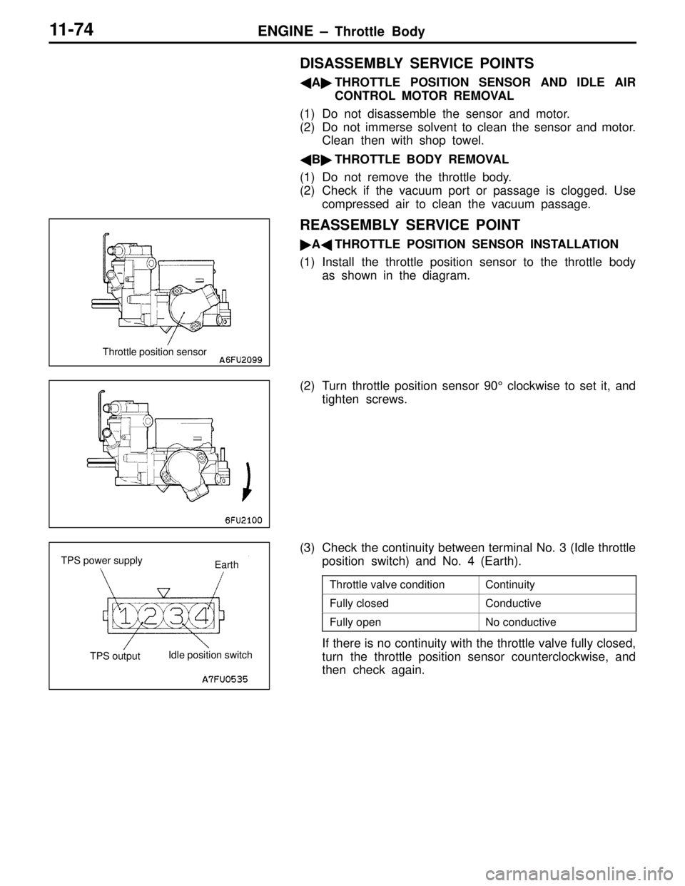
(1) Install the throttle position sensor to the throttle body
as shown in the diagram.
(2) Turn throttle position sensor 90° clockwise to set it, and
tighten screws.
(3) Check the continuity between terminal No. 3 (Idle throttle
position switch) and No. 4 (Earth).
Throttle valve conditionContinuity
Fully closedConductive
Fully openNo conductive
If there is no continuity with the throttle valve fully closed,
turn the throttle position sensor counterclockwise, and
then check again.
Throttle position sensor
Earth TPS power supply
TPS outputIdle position switch
Page 101 of 558
ENGINE – Turbocharger11-76
DISASSEMBLY SERVICE POINTS
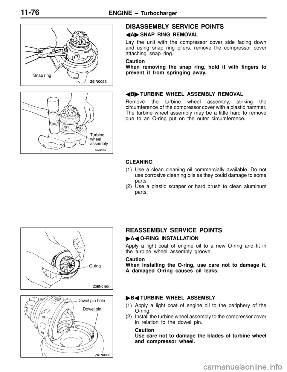
�A�SNAP RING REMOVAL
Lay the unit with the compressor cover side facing down
and using snap ring pliers, remove the compressor cover
attaching snap ring.
Caution
When removing the snap ring, hold it with fingers to
prevent it from springing away.
�B�TURBINE WHEEL ASSEMBLY REMOVAL
Remove the turbine wheel assembly, striking the
circumference of the compressor cover with a plastic hammer.
The turbine wheel assembly may be a little hard to remove
due to an O-ring put on the outer circumference.
CLEANING
(1) Use a clean cleaning oil commercially available. Do not
use corrosive cleaning oils as they could damage to some
parts.
(2) Use a plastic scraper or hard brush to clean aluminum
parts.
REASSEMBLY SERVICE POINTS
�A�O-RING INSTALLATION
Apply a light coat of engine oil to a new O-ring and fit in
the turbine wheel assembly groove.
Caution
When installing the O-ring, use care not to damage it.
A damaged O-ring causes oil leaks.
�B�TURBINE WHEEL ASSEMBLY
(1) Apply a light coat of engine oil to the periphery of the
O-ring.
(2) Install the turbine wheel assembly to the compressor cover
in relation to the dowel pin.
Caution
Use care not to damage the blades of turbine wheel
and compressor wheel.
Snap ring
Turbine
wheel
assembly
O-ring
Dowel pin hole
Dowel pin
Page 105 of 558
ENGINE – Alternator11-80
DISASSEMBLY SERVICE POINTS
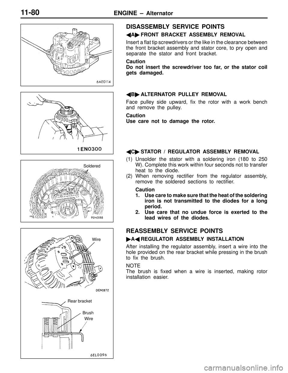
�A�FRONT BRACKET ASSEMBLY REMOVAL
Insert a flat tip screwdrivers or the like in the clearance between
the front bracket assembly and stator core, to pry open and
separate the stator and front bracket.
Caution
Do not insert the screwdriver too far, or the stator coil
gets damaged.
�B�ALTERNATOR PULLEY REMOVAL
Face pulley side upward, fix the rotor with a work bench
and remove the pulley.
Caution
Use care not to damage the rotor.
�C�STATOR / REGULATOR ASSEMBLY REMOVAL
(1) Unsolder the stator with a soldering iron (180 to 250
W). Complete this work within four seconds not to transfer
heat to the diode.
(2) When removing rectifier from the regulator assembly,
remove the soldered sections to rectifier.
Caution
1. Use care to make sure that the heat of the soldering
iron is not transmitted to the diodes for a long
period.
2. Use care that no undue force is exerted to the
lead wires of the diodes.
REASSEMBLY SERVICE POINTS
�A�REGULATOR ASSEMBLY INSTALLATION
After installing the regulator assembly, insert a wire into the
hole provided on the rear bracket while pressing in the brush
to fix the brush.
NOTE
The brush is fixed when a wire is inserted, making rotor
installation easier.
Soldered
Rear bracket
Brush
WireWire