Page 1557 of 1691
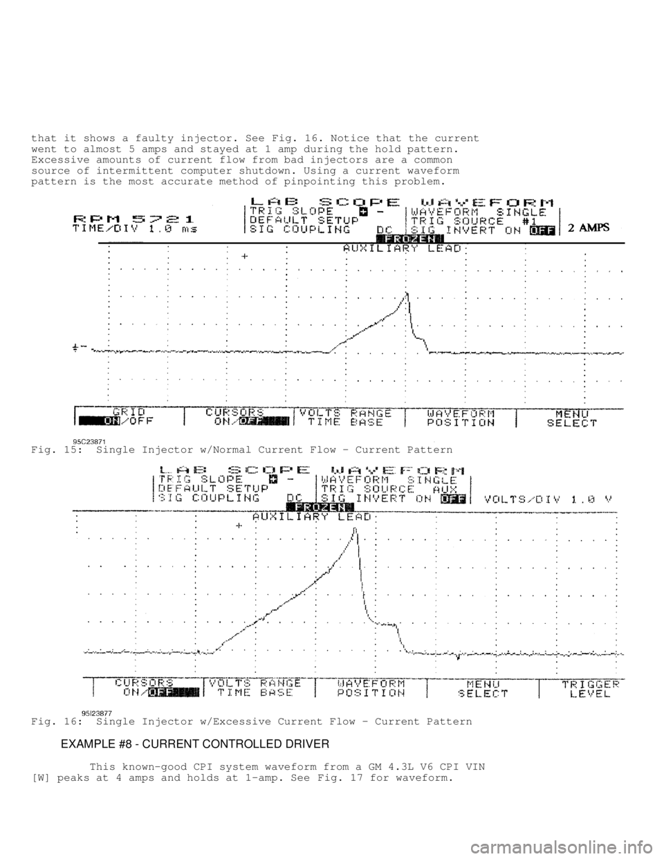
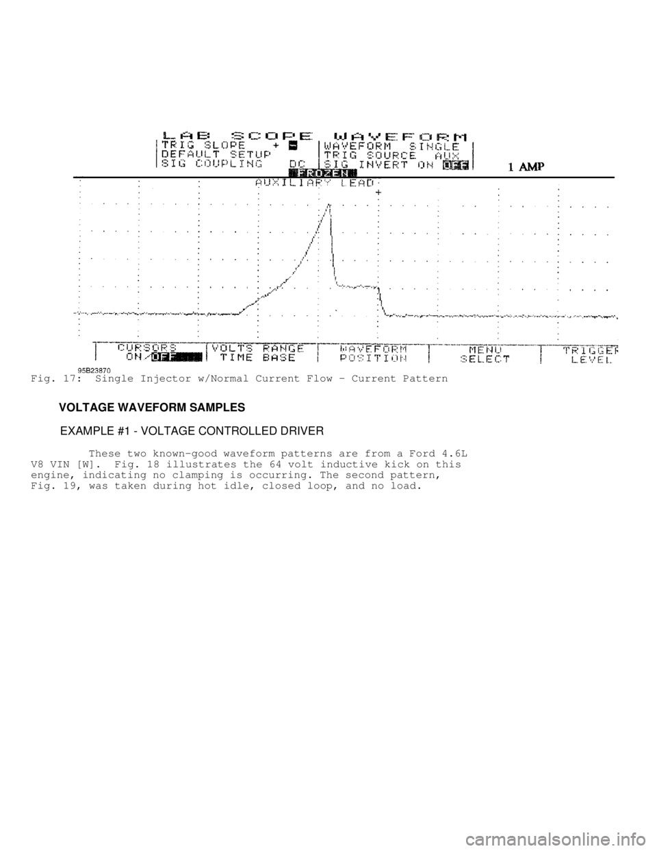
that it shows a faulty injector. See Fig. 16. Notice that the current
went to almost 5 amps and stayed at 1 amp during the hold pattern.
Excessive amounts of current flow from bad injectors are a common
source of intermittent computer shutdown. Using a current waveform
pattern is the most accurate method of pinpointing this problem.
Fig. 15: Single Injector w/Normal Current Flow - Current Pattern
Fig. 16: Single Injector w/Excessive Current Flow - Current Pattern
EXAMPLE #8 - CURRENT CONTROLLED DRIVER
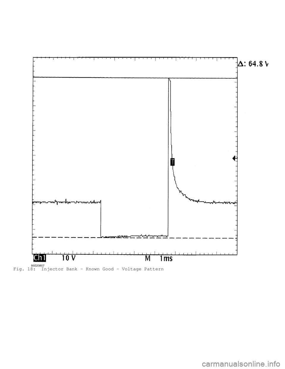
This known-good CPI system waveform from a GM 4.3L V6 CPI VIN
[W] peaks at 4 amps and holds at 1-amp. See Fig. 17 for waveform.
Page 1558 of 1691
Fig. 17: Single Injector w/Normal Current Flow - Current Pattern
VOLTAGE WAVEFORM SAMPLES
EXAMPLE #1 - VOLTAGE CONTROLLED DRIVER
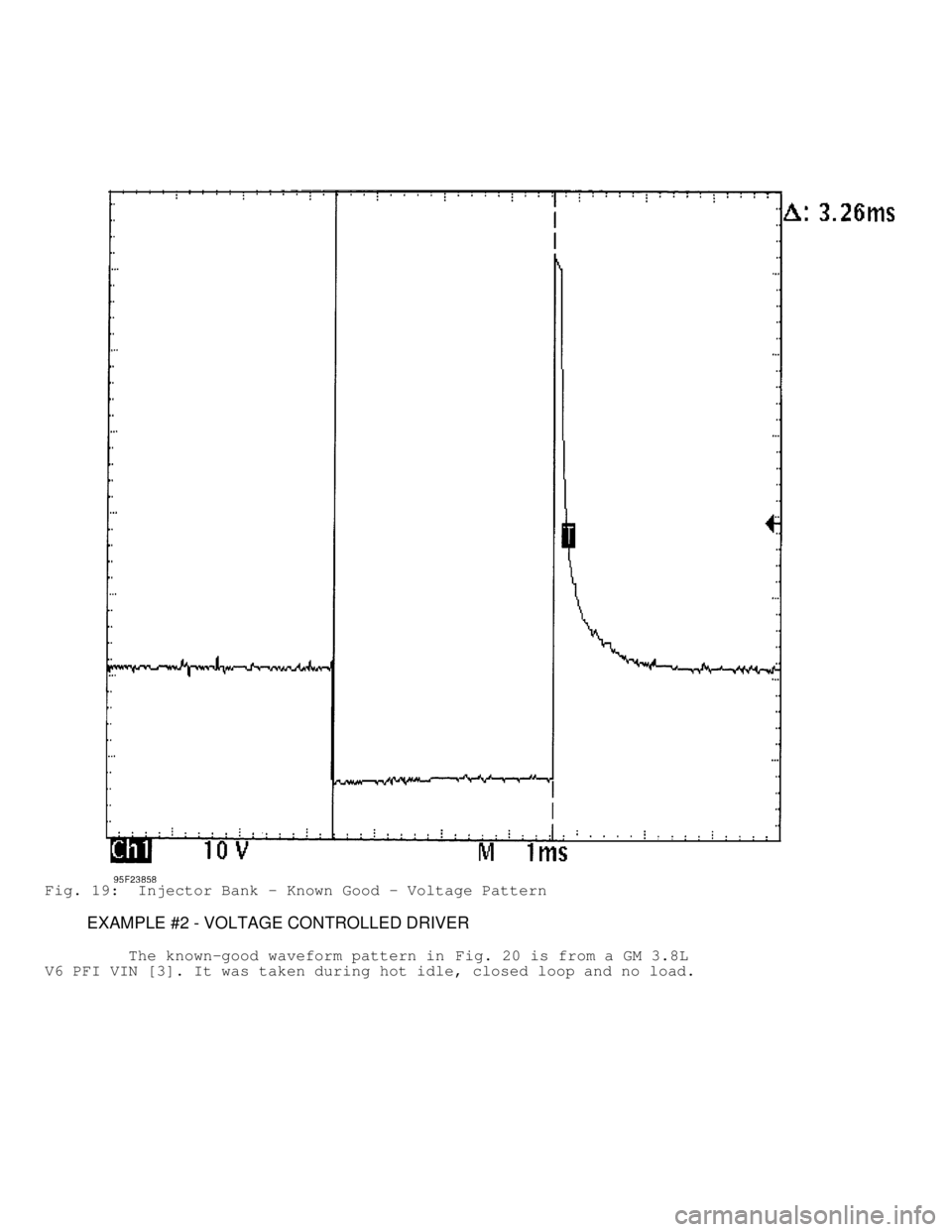
These two known-good waveform patterns are from a Ford 4.6L
V8 VIN [W]. Fig. 18 illustrates the 64 volt inductive kick on this
engine, indicating no clamping is occurring. The second pattern,
Fig. 19 , was taken during hot idle, closed loop, and no load.
Page 1559 of 1691
Fig. 18: Injector Bank - Known Good - Voltage Pattern
Page 1560 of 1691
Fig. 19: Injector Bank - Known Good - Voltage Pattern
EXAMPLE #2 - VOLTAGE CONTROLLED DRIVER
The known-good waveform pattern in Fig. 20 is from a GM 3.8L
V6 PFI VIN [3]. It was taken during hot idle, closed loop and no load.
Page 1561 of 1691
Fig. 20: Injector Bank - Known Good - Voltage Pattern
EXAMPLE #3 - VOLTAGE CONTROLLED DRIVER
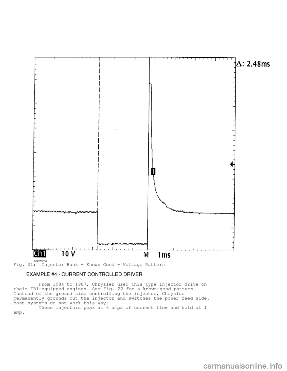
This known-good waveform pattern, Fig. 21, is from a GM 5.0L
V8 TPI VIN [F]. It was taken during hot idle, closed loop and no load.
Page 1562 of 1691
Fig. 21: Injector Bank - Known Good - Voltage Pattern
EXAMPLE #4 - CURRENT CONTROLLED DRIVER
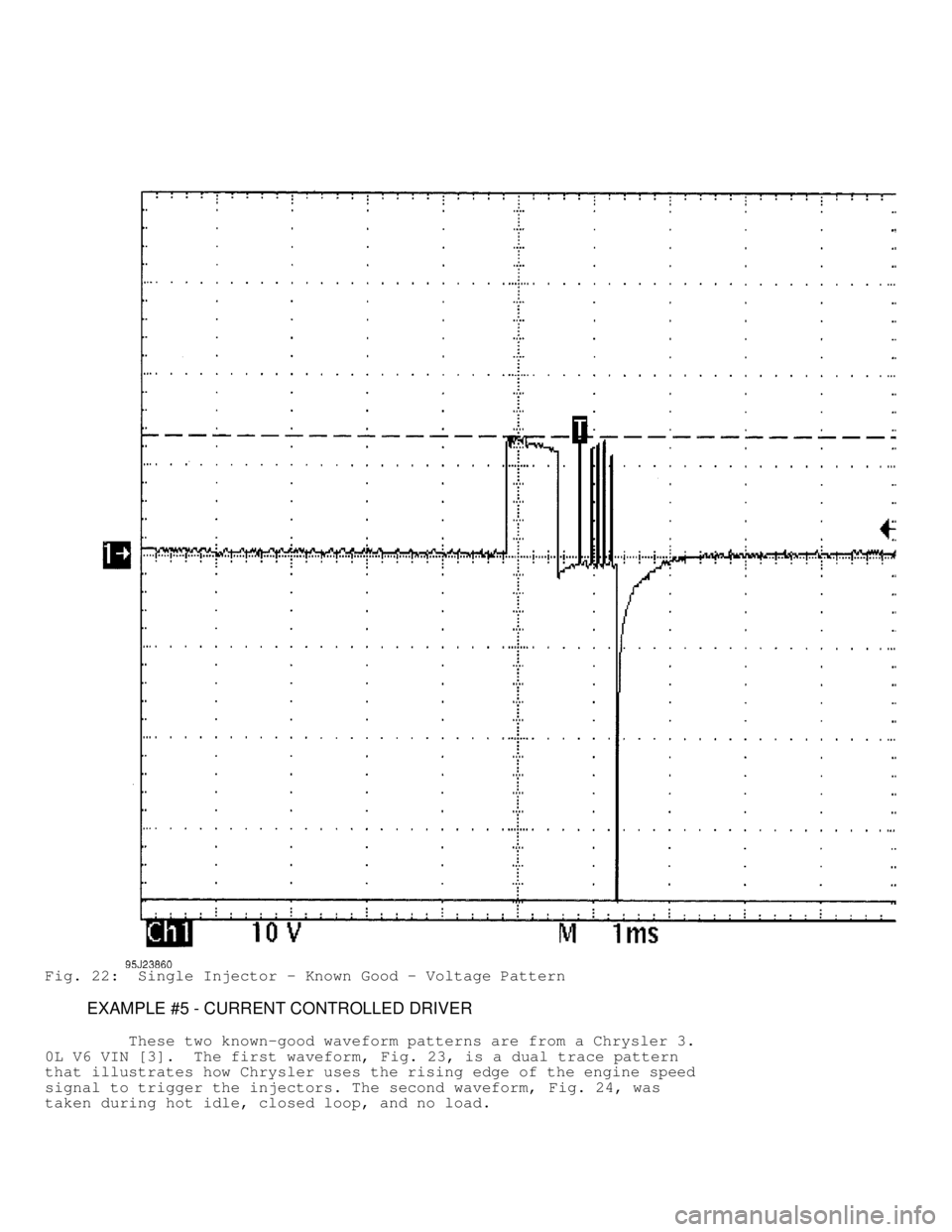
From 1984 to 1987, Chrysler used this type injector drive on
their TBI-equipped engines. See Fig. 22 for a known-good pattern.
Instead of the ground side controlling the injector, Chrysler
permanently grounds out the injector and switches the power feed side.
Most systems do not work this way.
These injectors peak at 6 amps of current flow and hold at 1
amp.
Page 1563 of 1691
Fig. 22: Single Injector - Known Good - Voltage Pattern
EXAMPLE #5 - CURRENT CONTROLLED DRIVER
These two known-good waveform patterns are from a Chrysler 3.
0L V6 VIN [3]. The first waveform, Fig. 23, is a dual trace pattern
that illustrates how Chrysler uses the rising edge of the engine speed
signal to trigger the injectors. The second waveform, Fig. 24, was
taken during hot idle, closed loop, and no load.
Page 1564 of 1691
Fig. 23: Injector Bank - Known Good - Voltage Pattern