1999 DODGE RAM Pulling engine
[x] Cancel search: Pulling enginePage 402 of 1691
Fully depress brake pedal and rotate brake switch
counterclockwise approximately 30 degrees. Remove brake switch from
bracket. Depress lock tabs holding brake switch mounting bracket and
separate harness connector from brake switch.
Installation
1) Before installing brake switch, reset adjustable plunger
by pulling on plunger head until plunger reaches end of travel.
Connect harness connector to brake switch. Depress brake pedal and
insert brake switch into keyed hole in mounting bracket. Rotate brake
switch clockwise into locked position.
2) Gently pull back on brake pedal until pedal will go no
further. This causes the brake switch plunger to ratchet backward to
the correct position. No further adjustment is required.
SPEED CONTROL SERVO
Removal (Except Ram Van & Ram Wagon)
1) Disconnect negative battery cable. Disconnect electrical
connector and vacuum hose from servo. Using finger pressure only, push
servo cable connector from throttle body bellcrank pin. DO NOT pull
cable connector perpendicular to bellcrank.
2) Remove 2 servo cable mounting nuts. Pull servo cable
sleeve away from mounting bracket to expose cable retaining clip.
Remove retaining clip. Remove servo.
Removal (Ram Van & Ram Wagon)
1) Disconnect negative battery cable. Remove engine cover.
Remove air cleaner assembly. Using finger pressure only, push servo
cable connector from throttle body bellcrank pin. DO NOT pull cable
connector perpendicular to bellcrank.
2) Remove right headlight assembly. Disconnect vacuum hose
and electrical connector at servo. Remove 2 servo mounting bracket
bolts. Remove 2 servo cable mounting nuts. Pull servo cable sleeve
away from mounting bracket to expose cable retaining clip. Remove
retaining clip. Remove servo.
Installation (All Models)
With throttle in full open position, align hole in speed
control cable sleeve with hole in servo pin. Install retaining clip.
To complete installation, reverse removal procedure. Tighten mounting
bolts/nuts to 75 INCH lbs. (8.5 N.m).
SPEED CONTROL SWITCHES
Removal & Installation
Turn ignition off. Disconnect negative battery cable. Wait 2
minutes for air bag system to discharge reserve voltage. Remove 2
screws holding air bag assembly to steering column. Separate air bag
assembly from steering column and disconnect air bag, horn and speed
control switch connectors. Remove screws securing speed control switch
to air bag assembly. Separate speed control switch from air bag
assembly. To install, reverse removal procedure.
WIRING DIAGRAMS
Page 649 of 1691
components, reverse removal procedure.
Removal (Dakota 4WD & Durango 4WD)
1) Disconnect negative battery cable. Remove oil dipstick.
Drain engine oil. Remove exhaust pipe crossover and lower transmission
cover.
2) Remove front drive axle for access to oil pan. For front
drive axle removal, loosen wheel lug nuts. Remove cotter pin, lock nut
and spring washer. Loosen axle shaft nut with vehicle on floor and
brakes applied. Raise and support vehicle.
CAUTION: DO NOT pull on rubber boot during axle shaft removal. Pull on
outer CV joint only.
3) Remove wheels and skid plate. Remove axle shaft nut.
Remove axle shaft-to-differential flange bolts at front drive axle.
Support axle shaft, and separate axle splines from wheel hub by
pulling inward at outer CV joint.
4) Remove remaining axle shaft. Mark front drive shaft and
transfer case yoke for installation reference. Remove front drive
shaft from transfer case. Disconnect vacuum hoses from shift motor and
electrical connections at shift indicator switch.
5) Support front drive axle using a floor jack. Remove front
drive axle and shift motor bolts. Lower floor jack, and remove front
drive axle with drive shaft. Remove transmission lower cover. Remove
bolts, oil pan and gasket.
Installation
1) To install, reverse removal procedure. Before installing
oil pan, apply RTV sealant where front cover contacts cylinder block,
oil pan side gaskets meet end seals and end seals contact cylinder
block. See Fig. 14.
2) To facilitate oil pan installation, fabricate 4 alignment
dowels from 1 1/2" x 5/16" bolts. See Fig. 15. Tighten bolts to
specification. See TORQUE SPECIFICATIONS table.
3) To install remaining components, reverse removal
procedure. When installing front drive axle, loosely install all bolts
before tightening to specification. Tighten axle shaft nut to
specification with vehicle on ground. See TORQUE SPECIFICATIONS table.
Ensure reference marks on transfer case yoke and front drive shaft are
aligned.
Removal (Ram Pickup & Ram Van/Wagon - 3.9L)
1) Disconnect negative battery cable. Remove oil dipstick. On
Ram Van/Wagon, remove engine cover. On all models, remove air cleaner
and engine controller. Raise and support vehicle. Drain engine oil.
2) Remove left engine-to-transmission strut. Loosen exhaust
pipe support bracket. Disconnect exhaust pipe. On Ram Pickup, remove
oil pan and gasket.
3) On Ram Van/Wagon, remove starter, transmission dust
shield, oxygen sensor and air injection tube. On all models, remove
right engine mount nut. Loosen, but DO NOT remove, left engine mount
nut.
4) Support right side of engine using jackstand. Remove
transmission mount through-bolt, and support transmission using
jackstand. Raise engine and transmission enough for oil pan removal.
Remove bolts, oil pan and gasket.
Installation
1) To install, reverse removal procedure. Before installing
oil pan, apply RTV sealant where front cover contacts cylinder block,
oil pan side gaskets meet end seals and end seals contact cylinder
block. See Fig. 14.
Page 926 of 1691
Removal (A/T Models)
Raise and support vehicle. Disconnect electrical connector
from park/neutral switch. Park/neutral switch is located on side of
transmission case, near shift linkage. Unscrew park/neutral switch
from transmission case. Remove seal ring from park/neutral switch.
Installation
1) Apply parking brake. Place shift lever in Park and
Neutral. Ensure park/neutral switch operating levers in transmission
are centered in the park/neutral switch opening on transmission case.
2) Using NEW seal ring, install park/neutral switch. Tighten
park/neutral switch to specification. See TORQUE SPECIFICATIONS.
Install electrical connector. Add ATF as necessary.
ACCELERATOR PEDAL POSITION SENSOR (APPS)
NOTE: APPS is replaced as assembly, including lever, brackets, and
sensor.
Removal
1) Disconnect negative battery cables. Remove cable cover.
Using finger pressure only, disconnect end of speed control servo
cable from throttle lever pin by pulling forward on connector while
holding lever rearward. Using 2 small screwdrivers, pry throttle cable
connector socket from throttle lever ball.
2) Disconnect transmission kickdown cable (if equipped).
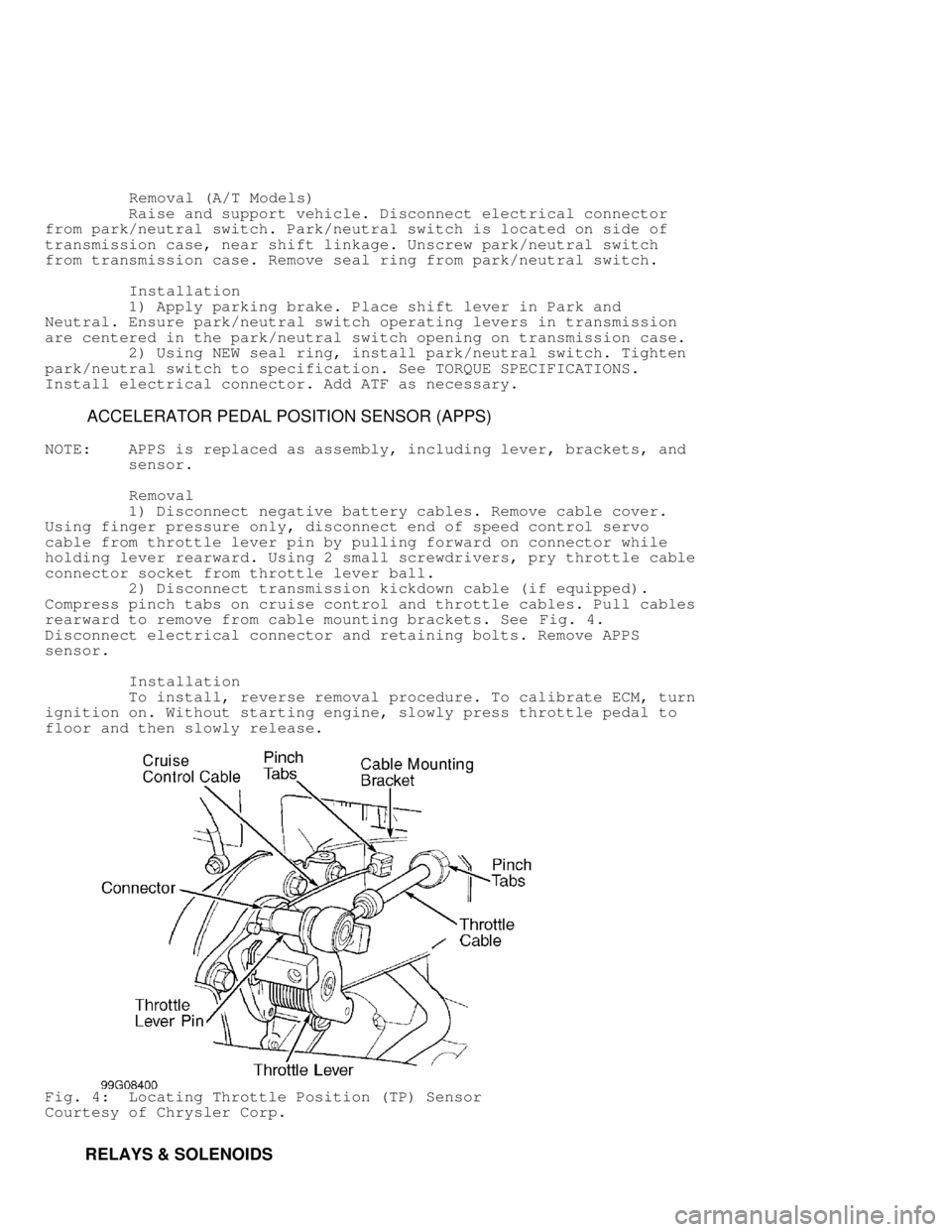
Compress pinch tabs on cruise control and throttle cables. Pull cables
rearward to remove from cable mounting brackets. See Fig. 4.
Disconnect electrical connector and retaining bolts. Remove APPS
sensor.
Installation
To install, reverse removal procedure. To calibrate ECM, turn
ignition on. Without starting engine, slowly press throttle pedal to
floor and then slowly release.
Fig. 4: Locating Throttle Position (TP) Sensor
Courtesy of Chrysler Corp.
RELAYS & SOLENOIDS
Page 946 of 1691
Removal
Downstream oxygen sensor is mounted on exhaust pipe, behind
catalytic converter. Raise and support vehicle. Disconnect electrical
connector for downstream oxygen sensor. Using Socket (YA8875), remove
downstream oxygen sensor from exhaust pipe.
Installation
If installing original or used downstream oxygen sensor,
apply anti-seize compound on threads of downstream oxygen sensor. A
NEW downstream oxygen sensor should already be coated with anti-seize
compound. Install and tighten downstream oxygen sensor to
specification. See TORQUE SPECIFICATIONS. Install electrical
connector.
ENGINE COOLANT TEMPERATURE SENSOR
Removal & Installation (Dakota 2.5L)
1) Partially drain cooling system. Disconnect electrical
connector at engine coolant temperature sensor. Engine coolant
temperature sensor is located on side of thermostat housing and
contains a Tan/Black wire and a Black/Light Blue wire in the
electrical connector.
2) Remove engine coolant temperature sensor. To install,
reverse removal procedure. Tighten engine coolant temperature sensor
to specification. See TORQUE SPECIFICATIONS. Fill cooling system.
Removal (Dakota 3.9L, 5.2L & 5.9L, Durango & Ram Pickup 3.9L,
5.2L & 5.9L)
1) Partially drain cooling system. Engine coolant temperature
sensor is located on front of intake manifold, near inside of
generator and contains a Tan/Black wire and a Black/Light Blue wire in
the electrical connector.
2) Remove air cleaner if necessary for access to engine
coolant temperature sensor. On models equipped with A/C, go to next
step. On models not equipped with A/C, disconnect electrical connector
at engine coolant temperature sensor. Remove engine coolant
temperature sensor.
3) On A/C equipped models, electrical connector on engine
coolant temperature sensor may be difficult to reach. It may be
necessary to use a coat hanger and fabricate an "L" shaped tool about
8" (203 mm) long to disconnect electrical connector by placing hook
part of tool under electrical connector and pulling electrical
connector upward from engine coolant temperature sensor. Remove engine
coolant temperature sensor.
Installation
To install, reverse removal procedure. Tighten engine coolant
temperature sensor to specification. See TORQUE SPECIFICATIONS. Fill
cooling system.
Removal & Installation (Ram Pickup 8.0L)
1) Partially drain cooling system. Engine coolant temperature
sensor is located on front of intake manifold, near rear of generator
and contains a Tan/Black wire and a Black/Light Blue wire in the
electrical connector.
2) Disconnect electrical connector at engine coolant
temperature sensor. Remove engine coolant temperature sensor.
3) To install, reverse removal procedure. Tighten engine
coolant temperature sensor to specification. See TORQUE
SPECIFICATIONS. Fill cooling system.
Removal (Ram Van & Ram Wagon)
Page 947 of 1691
1) Partially drain cooling system. Engine coolant temperature
sensor is located on front of intake manifold, near inside of
generator and contains a Tan/Black wire and a Black/Light Blue wire in
the electrical connector.
2) On 3.9L, remove engine cover and air cleaner housing from
inside of vehicle for access to engine coolant temperature sensor. On
5.2L and 5.9L, engine coolant temperature sensor may be serviced from
front of vehicle without removing engine cover and air cleaner
housing.
3) On all models, disconnect electrical connector at engine
coolant temperature sensor. It may be necessary to use a coat hanger
and fabricate an "L" shaped tool about 8" (203 mm) long to disconnect
electrical connector by placing hook part of tool under electrical
connector and pulling electrical connector upward from engine coolant
temperature sensor. Remove engine coolant temperature sensor.
Installation
To install, reverse removal procedure. Tighten engine coolant
temperature sensor to specification. See TORQUE SPECIFICATIONS. Fill
cooling system.
FUEL LEVEL SENSOR
Removal & Installation
See FUEL LEVEL SENSOR under FUEL SYSTEM.
INTAKE AIR TEMPERATURE (IAT) SENSOR
NOTE: Intake air temperature sensor may also be referred to as
intake manifold air temperature sensor.
Removal & Installation (Dakota, Durango & Ram Pickup)
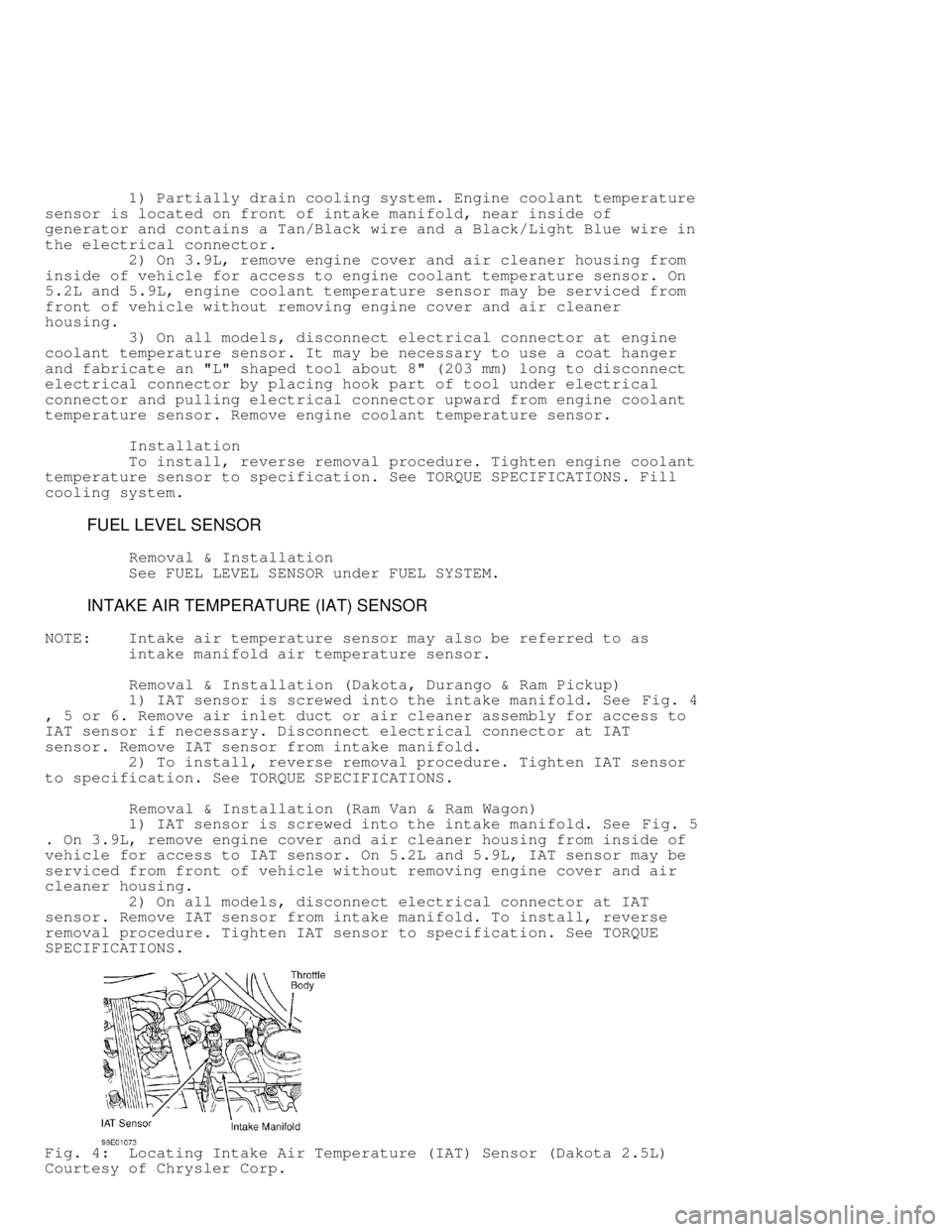
1) IAT sensor is screwed into the intake manifold. See Fig. 4
, 5 or 6. Remove air inlet duct or air cleaner assembly for access to
IAT sensor if necessary. Disconnect electrical connector at IAT
sensor. Remove IAT sensor from intake manifold.
2) To install, reverse removal procedure. Tighten IAT sensor
to specification. See TORQUE SPECIFICATIONS.
Removal & Installation (Ram Van & Ram Wagon)
1) IAT sensor is screwed into the intake manifold. See Fig. 5
. On 3.9L, remove engine cover and air cleaner housing from inside of
vehicle for access to IAT sensor. On 5.2L and 5.9L, IAT sensor may be
serviced from front of vehicle without removing engine cover and air
cleaner housing.
2) On all models, disconnect electrical connector at IAT
sensor. Remove IAT sensor from intake manifold. To install, reverse
removal procedure. Tighten IAT sensor to specification. See TORQUE
SPECIFICATIONS.
Fig. 4: Locating Intake Air Temperature (IAT) Sensor (Dakota 2.5L)
Courtesy of Chrysler Corp.
Page 1617 of 1691
bolster. Remove CTM from bracket on inboard side of instrument panel
steering column opening. Disconnect harness connectors. To install,
reverse removal procedure.
INTERMITTENT WIPER RELAY
Removal & Installation
Intermittent wiper relay is located in Power Distribution
Center (PDC) in engine compartment. Remove cover and remove relay. To
install, reverse removal procedures
WIPER ARMS
Removal & Installation
Open hood. Lift wiper and slide latch to hold wiper off of
windshield. With a rocking motion, remove wiper arm. To install,
ensure wiper motor is in park position. Slide wiper arm on shaft.
Align wiper arms. See WIPER BLADES under ADJUSTMENTS.
WIPER MOTOR
NOTE: Wiper linkage and motor module is replaced as a unit.
Removal & Installation
1) Disconnect negative battery cable. Remove wiper arms. See
WIPER ARMS. Remove weatherstrip along front edge of cowl. Release
plastic anchor screws. Lift cowl grille from vehicle. Remove washer
hose from "Y" fitting. Set grille aside.
2) Remove wiper linkage mounting bolts. Turn linkage over and
disconnect harness connector from wiper motor. Remove wiper linkage
and motor module. To install, reverse removal procedure. Align wiper
arms. See WIPER BLADES under ADJUSTMENTS.
WIPER/WASHER SWITCH
NOTE: Wiper/washer switch is part of multifunction steering column
switch. If wiper/washer switch fails, entire multifunction
switch must be replaced.
Removal & Installation
1) Disconnect negative battery cable. Remove tilt lever (if
equipped). Remove steering column upper and lower covers to access
switch connector. Remove switch connector. Remove multifunction switch
tamperproof screws.
2) Gently pull switch away from column and loosen connector
screw (screw remains in connector). Remove switch. To install, reverse\
removal procedure. Tighten screws and nuts to specification. See
TORQUE SPECIFICATIONS. Ensure switch is functioning properly.
WASHER RESERVOIR
Removal & Installation
Disconnect negative battery cable. Drain cooling system.
Disconnect upper radiator hose from radiator. Disconnect harness
connectors from washer pump and washer fluid level sensor. Remove
washer supply hose from washer pump and drain washer fluid. While
pulling reservoir away from fan shroud, lift reservoir upward to
disengage mounting tabs from fan shroud. Remove washer reservoir. To
install, reverse removal procedure.
WASHER MOTOR
Removal & Installation