1999 DODGE NEON heating
[x] Cancel search: heatingPage 888 of 1200

(7) Attach the other end of the jumper wire to
relay terminal 86. This activates the relay. The ohm-
meter should now show continuity between relay ter-
minals 87 and 30. The ohmmeter should not show
continuity between relay terminals 87A and 30.
(8) Disconnect jumper wires.
(9) Replace the relay if it did not pass the continu-
ity and resistance tests. If the relay passed the tests,
it operates properly. Check the remainder of the ASD
and fuel pump relay circuits. Refer to group 8W, Wir-
ing Diagrams.
CAMSHAFT AND CRANKSHAFT POSITION SENSOR
Refer to Group 8D, Ignition for Diagnosis and Test-
ing of Camshaft and Crankshaft Sensors.
ENGINE COOLANT TEMPERATURE SENSOR
(1) With the key off, disconnect wire harness con-
nector from coolant temperature sensor (Fig. 79) or
(Fig. 80).(2) Connect a high input impedance (digital) volt-
ohmmeter to terminals A and B (Fig. 81). The ohm-
meter should read as follows:
²Engine/Sensor at normal operating temperature
around 200ÉF should read approximately 700 to
1,000 ohms.
²Engine/Sensor at room temperature around 70ÉF
ohmmeter should read approximately 7,000 to 13,000
ohms.
(3) T
est the resistance of the wire harness between
the PCM 60-way connector terminal 28 and the sensor
harness connector. Also check for continuity between
PCM 60-way connector terminal 51 and the sensor har-
ness connector. Refer to Group 8W, Wiring diagrams for
circuit information. If the resistance is greater than 1
ohm, repair the wire harness as necessary.
HEATED OXYGEN SENSOR
Use an ohmmeter to test the heating element of
the oxygen sensors. Disconnect the electrical connec-
tor from each oxygen sensor. The white wires in the
sensor connector are the power and ground circuits
for the heater. Connect the ohmmeter test leads to
terminals of the white wires in the heated oxygen
sensor connector. Replace the heated oxygen sensor if
the resistance is not between 4 and 7 ohms.
IDLE AIR CONTROL (IAC) MOTOR TEST
To preform a complete test of IAC motor and its
circuitry, refer to DRB scan tool and the appropriate
Powertrain Diagnostics Procedures manual.
KNOCK SENSOR
The engine knock sensor is affected by a number of
factors. A few of these are: ignition timing, cylinder
pressure, fuel octane, etc. The knock sensor generates
an AC voltage whose amplitude increases with the
increase of engine knock. The knock sensor can be
tested with a digital voltmeter. The RMS voltage starts
Fig. 79 Engine Coolant Temperature Sensor
LocationÐSOHC
Fig. 80 Engine Coolant Temperature Sensor
LocationÐDOHC
Fig. 81 Engine Coolant Temperature Sensor
PLFUEL SYSTEM 14 - 47
DIAGNOSIS AND TESTING (Continued)
Page 1076 of 1200
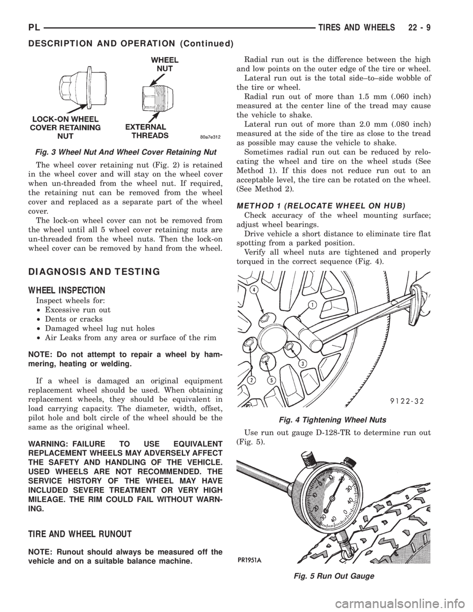
The wheel cover retaining nut (Fig. 2) is retained
in the wheel cover and will stay on the wheel cover
when un-threaded from the wheel nut. If required,
the retaining nut can be removed from the wheel
cover and replaced as a separate part of the wheel
cover.
The lock-on wheel cover can not be removed from
the wheel until all 5 wheel cover retaining nuts are
un-threaded from the wheel nuts. Then the lock-on
wheel cover can be removed by hand from the wheel.
DIAGNOSIS AND TESTING
WHEEL INSPECTION
Inspect wheels for:
²Excessive run out
²Dents or cracks
²Damaged wheel lug nut holes
²Air Leaks from any area or surface of the rim
NOTE: Do not attempt to repair a wheel by ham-
mering, heating or welding.
If a wheel is damaged an original equipment
replacement wheel should be used. When obtaining
replacement wheels, they should be equivalent in
load carrying capacity. The diameter, width, offset,
pilot hole and bolt circle of the wheel should be the
same as the original wheel.
WARNING: FAILURE TO USE EQUIVALENT
REPLACEMENT WHEELS MAY ADVERSELY AFFECT
THE SAFETY AND HANDLING OF THE VEHICLE.
USED WHEELS ARE NOT RECOMMENDED. THE
SERVICE HISTORY OF THE WHEEL MAY HAVE
INCLUDED SEVERE TREATMENT OR VERY HIGH
MILEAGE. THE RIM COULD FAIL WITHOUT WARN-
ING.
TIRE AND WHEEL RUNOUT
NOTE: Runout should always be measured off the
vehicle and on a suitable balance machine.Radial run out is the difference between the high
and low points on the outer edge of the tire or wheel.
Lateral run out is the total side±to±side wobble of
the tire or wheel.
Radial run out of more than 1.5 mm (.060 inch)
measured at the center line of the tread may cause
the vehicle to shake.
Lateral run out of more than 2.0 mm (.080 inch)
measured at the side of the tire as close to the tread
as possible may cause the vehicle to shake.
Sometimes radial run out can be reduced by relo-
cating the wheel and tire on the wheel studs (See
Method 1). If this does not reduce run out to an
acceptable level, the tire can be rotated on the wheel.
(See Method 2).
METHOD 1 (RELOCATE WHEEL ON HUB)
Check accuracy of the wheel mounting surface;
adjust wheel bearings.
Drive vehicle a short distance to eliminate tire flat
spotting from a parked position.
Verify all wheel nuts are tightened and properly
torqued in the correct sequence (Fig. 4).
Use run out gauge D-128-TR to determine run out
(Fig. 5).
Fig. 3 Wheel Nut And Wheel Cover Retaining Nut
Fig. 4 Tightening Wheel Nuts
Fig. 5 Run Out Gauge
PLTIRES AND WHEELS 22 - 9
DESCRIPTION AND OPERATION (Continued)
Page 1134 of 1200
HEATING AND AIR CONDITIONING
CONTENTS
page page
GENERAL INFORMATION
INTRODUCTION......................... 2
SAFETY PRECAUTIONS AND WARNINGS..... 2
DESCRIPTION AND OPERATION
A/C REFRIGERANT LINES................. 3
BLOWER MOTOR RESISTOR............... 3
COMPRESSOR FRONT SHAFT SEAL......... 4
COMPRESSOR.......................... 4
CONDENSATION DRAIN TUBE.............. 4
ENGINE COOLING SSTEM
REQUIREMENTS....................... 4
EVAPORATOR PROBE..................... 4
HANDLING TUBING AND FITTINGS.......... 4
HIGH PRESSURE CUT OUT SWITCH......... 5
LOW PRESSURE CUT OFF SWITCH......... 5
SIDE WINDOW DEMISTERS............... 5
SYSTEM AIRFLOW....................... 5
SYSTEM OIL LEVEL...................... 6
VACUUM CONTROL SYSTEM............... 6
DIAGNOSIS AND TESTING
A/C PERFORMANCE TEST................. 6
BLOWER MOTOR ELECTRICAL DIAGNOSIS . . . 8
BLOWER MOTOR VIBRATION
AND/OR NOISE DIAGNOSIS.............. 8
COMPRESSOR NOISE DIAGNOSIS.......... 7
EVAPORATOR PROBE TEST................ 8
EXPANSION VALVE....................... 7
HEATER PERFORMANCE TEST............. 8
LOW PRESSURE CUT-OFF SWITCH......... 11
SYSTEM CHARGE LEVEL TEST............ 11
VACUUM CONTROL SYSTEM.............. 12
SERVICE PROCEDURES
CHARGING A/C SYSTEM................. 14
EVACUATING REFRIGERANT SYSTEM....... 15R-134a REFRIGERANT................... 16
SERVICING REFRIGERANT OIL LEVEL...... 17
SYSTEM LEAK CHECKING................ 17
REMOVAL AND INSTALLATION
A/C FILTER/DRIER...................... 23
A/C SERVICE PORT VALVE CORES......... 18
BLOWER MOTOR AND WHEEL ASSEMBLY . . . 18
BLOWER MOTOR RESISTOR.............. 18
BLOWER MOTOR WHEEL................ 19
COMPRESSOR CLUTCH/COIL ASSEMBLY.... 19
COMPRESSOR......................... 19
CONDENSATION DRAIN TUBE............ 21
CONDENSER........................... 21
DISCHARGE LINE....................... 21
EVAPORATOR PROBE.................... 22
EVAPORATOR.......................... 21
EXPANSION VALVE...................... 23
HEATER CORE......................... 24
HEATER HOSES........................ 24
HIGH PRESSURE CUT OUT SWITCH........ 23
HIGH PRESSURE RELIEF VALVE........... 24
LIQUID LINE........................... 25
LOW PRESSURE CUT OFF SWITCH........ 25
MODE CONTROL CABLE................. 25
RECIRCULATION DOOR ACTUATOR........ 26
SUCTION LINE......................... 27
TEMPERATURE CONTROL CABLE.......... 27
UNIT HOUSING......................... 27
DISASSEMBLY AND ASSEMBLY
AIR DISTRIBUTION MODULE ±
RECONDITION........................ 28
ADJUSTMENTS
MODE CONTROL CABLE................. 30
TEMPERATURE CONTROL CABLE.......... 30
PLHEATING AND AIR CONDITIONING 24 - 1
Page 1135 of 1200
GENERAL INFORMATION
INTRODUCTION
Both the heater and the heater/air conditioning
systems share many of the same functioning compo-
nents. This group will deal with both systems
together when component function is common, and
separately when they are not.
For proper operation of the instrument panel con-
trols, refer to the Owner's Manual provided with the
vehicle.
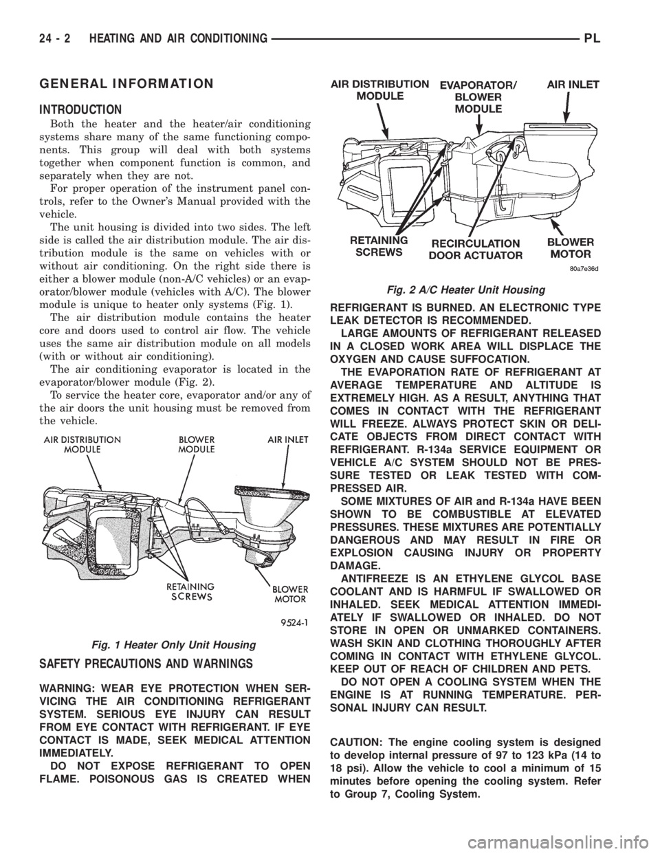
The unit housing is divided into two sides. The left
side is called the air distribution module. The air dis-
tribution module is the same on vehicles with or
without air conditioning. On the right side there is
either a blower module (non-A/C vehicles) or an evap-
orator/blower module (vehicles with A/C). The blower
module is unique to heater only systems (Fig. 1).
The air distribution module contains the heater
core and doors used to control air flow. The vehicle
uses the same air distribution module on all models
(with or without air conditioning).
The air conditioning evaporator is located in the
evaporator/blower module (Fig. 2).
To service the heater core, evaporator and/or any of
the air doors the unit housing must be removed from
the vehicle.
SAFETY PRECAUTIONS AND WARNINGS
WARNING: WEAR EYE PROTECTION WHEN SER-
VICING THE AIR CONDITIONING REFRIGERANT
SYSTEM. SERIOUS EYE INJURY CAN RESULT
FROM EYE CONTACT WITH REFRIGERANT. IF EYE
CONTACT IS MADE, SEEK MEDICAL ATTENTION
IMMEDIATELY.
DO NOT EXPOSE REFRIGERANT TO OPEN
FLAME. POISONOUS GAS IS CREATED WHENREFRIGERANT IS BURNED. AN ELECTRONIC TYPE
LEAK DETECTOR IS RECOMMENDED.
LARGE AMOUNTS OF REFRIGERANT RELEASED
IN A CLOSED WORK AREA WILL DISPLACE THE
OXYGEN AND CAUSE SUFFOCATION.
THE EVAPORATION RATE OF REFRIGERANT AT
AVERAGE TEMPERATURE AND ALTITUDE IS
EXTREMELY HIGH. AS A RESULT, ANYTHING THAT
COMES IN CONTACT WITH THE REFRIGERANT
WILL FREEZE. ALWAYS PROTECT SKIN OR DELI-
CATE OBJECTS FROM DIRECT CONTACT WITH
REFRIGERANT. R-134a SERVICE EQUIPMENT OR
VEHICLE A/C SYSTEM SHOULD NOT BE PRES-
SURE TESTED OR LEAK TESTED WITH COM-
PRESSED AIR.
SOME MIXTURES OF AIR and R-134a HAVE BEEN
SHOWN TO BE COMBUSTIBLE AT ELEVATED
PRESSURES. THESE MIXTURES ARE POTENTIALLY
DANGEROUS AND MAY RESULT IN FIRE OR
EXPLOSION CAUSING INJURY OR PROPERTY
DAMAGE.
ANTIFREEZE IS AN ETHYLENE GLYCOL BASE
COOLANT AND IS HARMFUL IF SWALLOWED OR
INHALED. SEEK MEDICAL ATTENTION IMMEDI-
ATELY IF SWALLOWED OR INHALED. DO NOT
STORE IN OPEN OR UNMARKED CONTAINERS.
WASH SKIN AND CLOTHING THOROUGHLY AFTER
COMING IN CONTACT WITH ETHYLENE GLYCOL.
KEEP OUT OF REACH OF CHILDREN AND PETS.
DO NOT OPEN A COOLING SYSTEM WHEN THE
ENGINE IS AT RUNNING TEMPERATURE. PER-
SONAL INJURY CAN RESULT.
CAUTION: The engine cooling system is designed
to develop internal pressure of 97 to 123 kPa (14 to
18 psi). Allow the vehicle to cool a minimum of 15
minutes before opening the cooling system. Refer
to Group 7, Cooling System.
Fig. 2 A/C Heater Unit Housing
Fig. 1 Heater Only Unit Housing
24 - 2 HEATING AND AIR CONDITIONINGPL
Page 1136 of 1200
DESCRIPTION AND OPERATION
A/C REFRIGERANT LINES
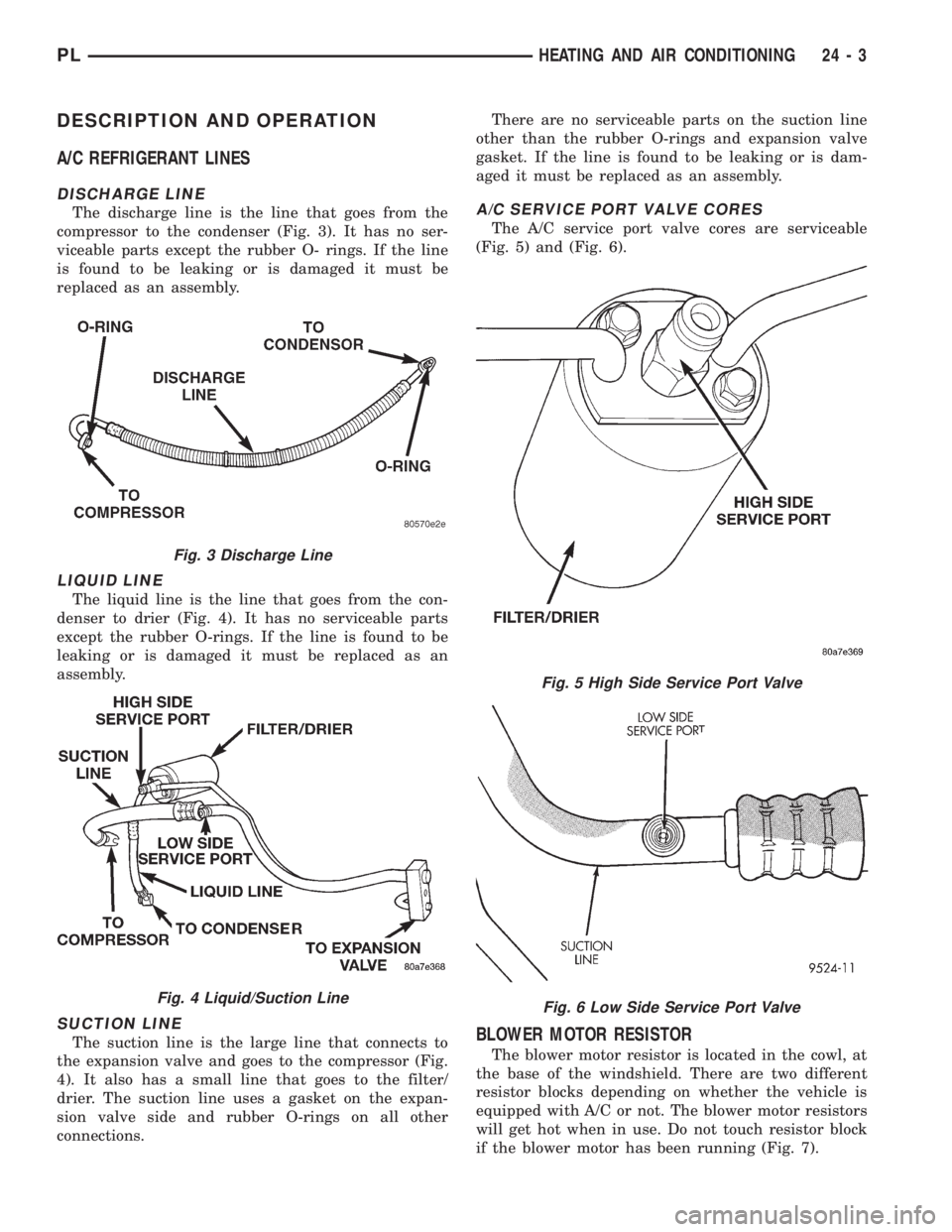
DISCHARGE LINE
The discharge line is the line that goes from the
compressor to the condenser (Fig. 3). It has no ser-
viceable parts except the rubber O- rings. If the line
is found to be leaking or is damaged it must be
replaced as an assembly.
LIQUID LINE
The liquid line is the line that goes from the con-
denser to drier (Fig. 4). It has no serviceable parts
except the rubber O-rings. If the line is found to be
leaking or is damaged it must be replaced as an
assembly.
SUCTION LINE
The suction line is the large line that connects to
the expansion valve and goes to the compressor (Fig.
4). It also has a small line that goes to the filter/
drier. The suction line uses a gasket on the expan-
sion valve side and rubber O-rings on all other
connections.There are no serviceable parts on the suction line
other than the rubber O-rings and expansion valve
gasket. If the line is found to be leaking or is dam-
aged it must be replaced as an assembly.
A/C SERVICE PORT VALVE CORES
The A/C service port valve cores are serviceable
(Fig. 5) and (Fig. 6).
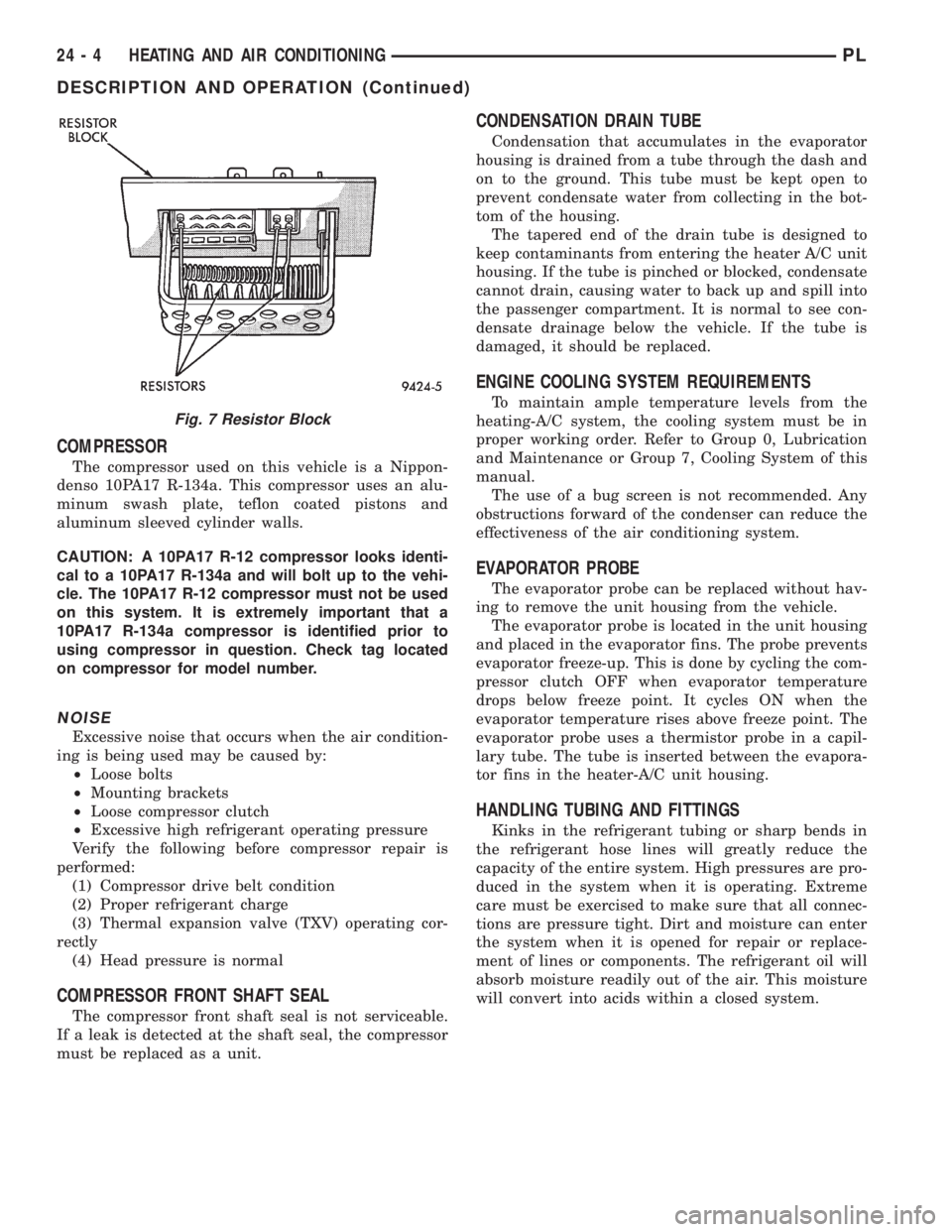
BLOWER MOTOR RESISTOR
The blower motor resistor is located in the cowl, at
the base of the windshield. There are two different
resistor blocks depending on whether the vehicle is
equipped with A/C or not. The blower motor resistors
will get hot when in use. Do not touch resistor block
if the blower motor has been running (Fig. 7).
Fig. 3 Discharge Line
Fig. 4 Liquid/Suction Line
Fig. 5 High Side Service Port Valve
Fig. 6 Low Side Service Port Valve
PLHEATING AND AIR CONDITIONING 24 - 3
Page 1137 of 1200
COMPRESSOR
The compressor used on this vehicle is a Nippon-
denso 10PA17 R-134a. This compressor uses an alu-
minum swash plate, teflon coated pistons and
aluminum sleeved cylinder walls.
CAUTION: A 10PA17 R-12 compressor looks identi-
cal to a 10PA17 R-134a and will bolt up to the vehi-
cle. The 10PA17 R-12 compressor must not be used
on this system. It is extremely important that a
10PA17 R-134a compressor is identified prior to
using compressor in question. Check tag located
on compressor for model number.
NOISE
Excessive noise that occurs when the air condition-
ing is being used may be caused by:
²Loose bolts
²Mounting brackets
²Loose compressor clutch
²Excessive high refrigerant operating pressure
Verify the following before compressor repair is
performed:
(1) Compressor drive belt condition
(2) Proper refrigerant charge
(3) Thermal expansion valve (TXV) operating cor-
rectly
(4) Head pressure is normal
COMPRESSOR FRONT SHAFT SEAL
The compressor front shaft seal is not serviceable.
If a leak is detected at the shaft seal, the compressor
must be replaced as a unit.
CONDENSATION DRAIN TUBE
Condensation that accumulates in the evaporator
housing is drained from a tube through the dash and
on to the ground. This tube must be kept open to
prevent condensate water from collecting in the bot-
tom of the housing.
The tapered end of the drain tube is designed to
keep contaminants from entering the heater A/C unit
housing. If the tube is pinched or blocked, condensate
cannot drain, causing water to back up and spill into
the passenger compartment. It is normal to see con-
densate drainage below the vehicle. If the tube is
damaged, it should be replaced.
ENGINE COOLING SYSTEM REQUIREMENTS
To maintain ample temperature levels from the
heating-A/C system, the cooling system must be in
proper working order. Refer to Group 0, Lubrication
and Maintenance or Group 7, Cooling System of this
manual.
The use of a bug screen is not recommended. Any
obstructions forward of the condenser can reduce the
effectiveness of the air conditioning system.
EVAPORATOR PROBE
The evaporator probe can be replaced without hav-
ing to remove the unit housing from the vehicle.
The evaporator probe is located in the unit housing
and placed in the evaporator fins. The probe prevents
evaporator freeze-up. This is done by cycling the com-
pressor clutch OFF when evaporator temperature
drops below freeze point. It cycles ON when the
evaporator temperature rises above freeze point. The
evaporator probe uses a thermistor probe in a capil-
lary tube. The tube is inserted between the evapora-
tor fins in the heater-A/C unit housing.
HANDLING TUBING AND FITTINGS
Kinks in the refrigerant tubing or sharp bends in
the refrigerant hose lines will greatly reduce the
capacity of the entire system. High pressures are pro-
duced in the system when it is operating. Extreme
care must be exercised to make sure that all connec-
tions are pressure tight. Dirt and moisture can enter
the system when it is opened for repair or replace-
ment of lines or components. The refrigerant oil will
absorb moisture readily out of the air. This moisture
will convert into acids within a closed system.
Fig. 7 Resistor Block
24 - 4 HEATING AND AIR CONDITIONINGPL
DESCRIPTION AND OPERATION (Continued)
Page 1138 of 1200
CAUTION: The system must be completely empty
before opening any fitting or connection in the
refrigeration system. Open fittings with caution
even after the system has been emptied. If any
pressure is noticed as a fitting is loosened,
retighten fitting and evacuate the system again.
A good rule for the flexible hose lines is to keep
the radius of all bends at least 10 times the diame-
ter of the hose. Sharper bends will reduce the flow
of refrigerant. The flexible hose lines should be
routed so they are at least 3 inches (80 mm) from
the exhaust manifold. Inspect all flexible hose lines
to make sure they are in good condition and prop-
erly routed.
The use of correct wrenches when making con-
nections is very important. Improper wrenches or
improper use of wrenches can damage the fittings.
The internal parts of the A/C system will remain
stable as long as moisture-free refrigerant and
refrigerant oil is used. Abnormal amounts of dirt,
moisture or air can upset the chemical stability.
This may cause operational troubles or even seri-
ous damage if present in more than very small
quantities.
When opening a refrigeration system, have every-
thing you will need to repair the system ready. This
will minimize the amount of time the system must
be opened. Cap or plug all lines and fittings as
soon as they are opened. This will help prevent the
entrance of dirt and moisture. All new lines and
components should be capped or sealed until they
are ready to be used.
All tools, including the refrigerant dispensing
manifold, the manifold gauge set, and test hoses
should be kept clean and dry.
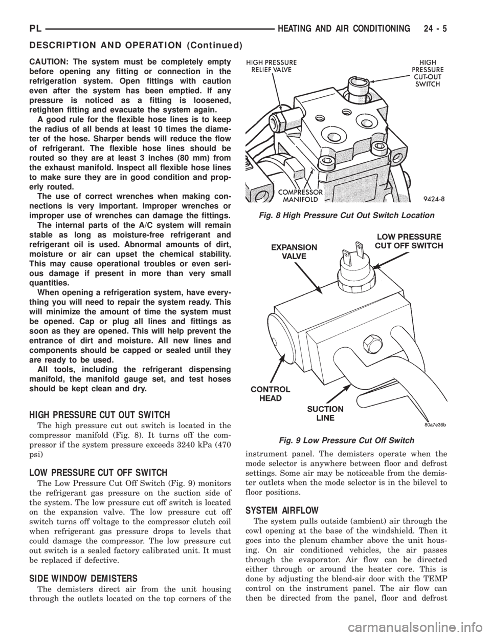
HIGH PRESSURE CUT OUT SWITCH
The high pressure cut out switch is located in the
compressor manifold (Fig. 8). It turns off the com-
pressor if the system pressure exceeds 3240 kPa (470
psi)
LOW PRESSURE CUT OFF SWITCH
The Low Pressure Cut Off Switch (Fig. 9) monitors
the refrigerant gas pressure on the suction side of
the system. The low pressure cut off switch is located
on the expansion valve. The low pressure cut off
switch turns off voltage to the compressor clutch coil
when refrigerant gas pressure drops to levels that
could damage the compressor. The low pressure cut
out switch is a sealed factory calibrated unit. It must
be replaced if defective.
SIDE WINDOW DEMISTERS
The demisters direct air from the unit housing
through the outlets located on the top corners of theinstrument panel. The demisters operate when the
mode selector is anywhere between floor and defrost
settings. Some air may be noticeable from the demis-
ter outlets when the mode selector is in the bilevel to
floor positions.
SYSTEM AIRFLOW
The system pulls outside (ambient) air through the
cowl opening at the base of the windshield. Then it
goes into the plenum chamber above the unit hous-
ing. On air conditioned vehicles, the air passes
through the evaporator. Air flow can be directed
either through or around the heater core. This is
done by adjusting the blend-air door with the TEMP
control on the instrument panel. The air flow can
then be directed from the panel, floor and defrost
Fig. 8 High Pressure Cut Out Switch Location
Fig. 9 Low Pressure Cut Off Switch
PLHEATING AND AIR CONDITIONING 24 - 5
DESCRIPTION AND OPERATION (Continued)
Page 1139 of 1200
outlets in various combinations using the mode selec-
tor. There are 17 different mode selections possible.
Air flow velocity can be adjusted with the blower
speed selector switch on the instrument panel.
On A/C equipped vehicles the ambient air intake
can be controlled by opening and closing the recircu-
lating air door. When placed in RECIRC, air that is
inside vehicle is removed continuously and recircu-
lated through unit housing. Ambient air cannot be
controlled on vehicles without A/C. The system uses
outside air at all times.
The air conditioning compressor can be engaged by
turning the fan switch counterclockwise from the off
position. It can also be engaged by placing the mode
control in the defrost position. This will remove heat
and humidity from the air before it is directed
through or around the heater core.
SYSTEM OIL LEVEL
It is important to have the correct amount of oil in
the A/C system to ensure proper lubrication of the
compressor. Too little oil will result in damage to the
compressor. Too much oil will reduce the cooling
capacity of the system and consequently result in
higher discharge air temperatures.
NOTE: The oil used in the compressor is ND8 PAG
R-134a refrigerant oil. Only refrigerant oil of the
same type should be used to service the system.
Do not use any other oil. The oil container should
be kept tightly capped until it is ready for use.
Tightly cap afterwards to prevent contamination
from dirt and moisture. Refrigerant oil will quickly
absorb any moisture it comes in contact with. Spe-
cial effort must be used to keep all R-134a system
components moisture-free. Moisture in the oil is
very difficult to remove and will cause a reliability
problem with the compressor.
It will not be necessary to check oil level in the
compressor or to add oil unless there has been an oil
loss. Oil loss at a leak point will be evident by the
presence of a wet, shiny surface around the leak.
REFRIGERANT OIL LEVEL CHECK
When an air conditioning system is first assem-
bled, all components (except the compressor) are
refrigerant oil free. After the system has been
charged with R-134a refrigerant and operated, the oil
in the compressor is dispersed through the lines and
components. The evaporator, condenser, and filter-
drier will retain a significant amount of oil, refer to
the Refrigerant Oil Capacities chart. When a compo-
nent is replaced, the specified amount of refrigerant
oil must be added. When the compressor is replaced,
the amount of oil that is retained in the rest of the
system must be drained from the replacement com-pressor. When a line or component has ruptured and
oil has escaped, the compressor should be removed
and drained. The filter-drier must be replaced along
with the ruptured part. The oil capacity of the sys-
tem, minus the amount of oil still in the remaining
components, can be measured and poured into the
suction port of the compressor.
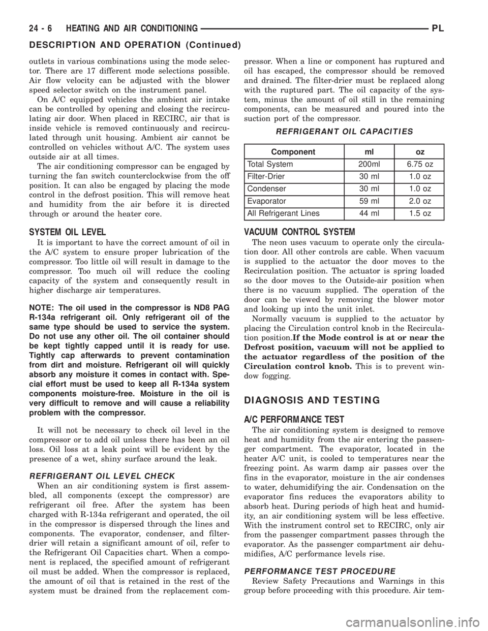
VACUUM CONTROL SYSTEM
The neon uses vacuum to operate only the circula-
tion door. All other controls are cable. When vacuum
is supplied to the actuator the door moves to the
Recirculation position. The actuator is spring loaded
so the door moves to the Outside-air position when
there is no vacuum supplied. The operation of the
door can be viewed by removing the blower motor
and looking up into the unit inlet.
Normally vacuum is supplied to the actuator by
placing the Circulation control knob in the Recircula-
tion position.If the Mode control is at or near the
Defrost position, vacuum will not be applied to
the actuator regardless of the position of the
Circulation control knob.This is to prevent win-
dow fogging.
DIAGNOSIS AND TESTING
A/C PERFORMANCE TEST
The air conditioning system is designed to remove
heat and humidity from the air entering the passen-
ger compartment. The evaporator, located in the
heater A/C unit, is cooled to temperatures near the
freezing point. As warm damp air passes over the
fins in the evaporator, moisture in the air condenses
to water, dehumidifying the air. Condensation on the
evaporator fins reduces the evaporators ability to
absorb heat. During periods of high heat and humid-
ity, an air conditioning system will be less effective.
With the instrument control set to RECIRC, only air
from the passenger compartment passes through the
evaporator. As the passenger compartment air dehu-
midifies, A/C performance levels rise.
PERFORMANCE TEST PROCEDURE
Review Safety Precautions and Warnings in this
group before proceeding with this procedure. Air tem-
REFRIGERANT OIL CAPACITIES
Component ml oz
Total System 200ml 6.75 oz
Filter-Drier 30 ml 1.0 oz
Condenser 30 ml 1.0 oz
Evaporator 59 ml 2.0 oz
All Refrigerant Lines 44 ml 1.5 oz
24 - 6 HEATING AND AIR CONDITIONINGPL
DESCRIPTION AND OPERATION (Continued)