1999 DODGE NEON radiator cap
[x] Cancel search: radiator capPage 208 of 1200
There may be internal leaks, which can be deter-
mined by removing the oil dipstick. If water globules
appear intermixed with the oil, it indicates an inter-
nal leak in the engine. If there is an internal leak,
the engine must be disassembled for repair.
PRESSURE CAP TO FILLER NECK SEAL
PRESSURE RELIEF CHECK
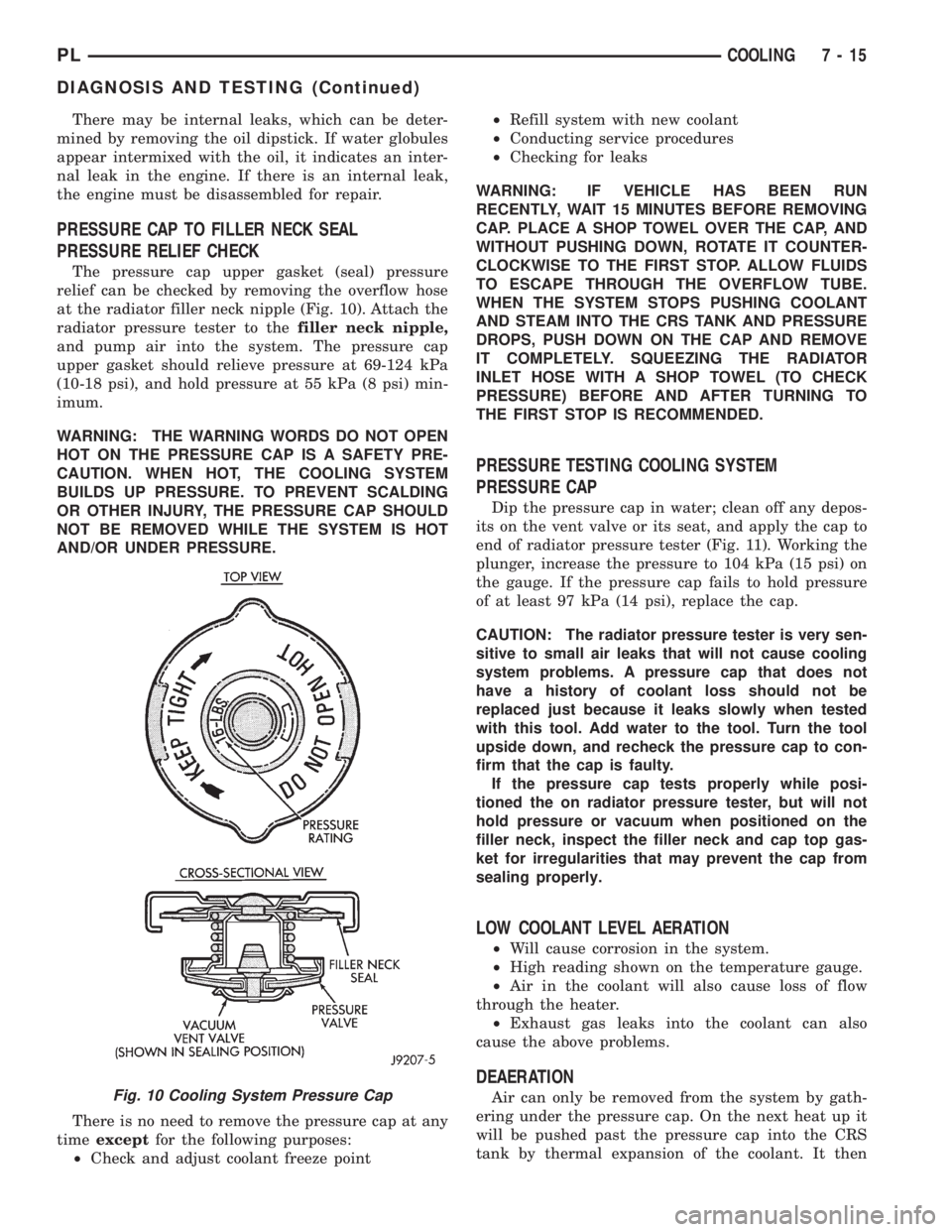
The pressure cap upper gasket (seal) pressure
relief can be checked by removing the overflow hose
at the radiator filler neck nipple (Fig. 10). Attach the
radiator pressure tester to thefiller neck nipple,
and pump air into the system. The pressure cap
upper gasket should relieve pressure at 69-124 kPa
(10-18 psi), and hold pressure at 55 kPa (8 psi) min-
imum.
WARNING: THE WARNING WORDS DO NOT OPEN
HOT ON THE PRESSURE CAP IS A SAFETY PRE-
CAUTION. WHEN HOT, THE COOLING SYSTEM
BUILDS UP PRESSURE. TO PREVENT SCALDING
OR OTHER INJURY, THE PRESSURE CAP SHOULD
NOT BE REMOVED WHILE THE SYSTEM IS HOT
AND/OR UNDER PRESSURE.
There is no need to remove the pressure cap at any
timeexceptfor the following purposes:
²Check and adjust coolant freeze point²Refill system with new coolant
²Conducting service procedures
²Checking for leaks
WARNING: IF VEHICLE HAS BEEN RUN
RECENTLY, WAIT 15 MINUTES BEFORE REMOVING
CAP. PLACE A SHOP TOWEL OVER THE CAP, AND
WITHOUT PUSHING DOWN, ROTATE IT COUNTER-
CLOCKWISE TO THE FIRST STOP. ALLOW FLUIDS
TO ESCAPE THROUGH THE OVERFLOW TUBE.
WHEN THE SYSTEM STOPS PUSHING COOLANT
AND STEAM INTO THE CRS TANK AND PRESSURE
DROPS, PUSH DOWN ON THE CAP AND REMOVE
IT COMPLETELY. SQUEEZING THE RADIATOR
INLET HOSE WITH A SHOP TOWEL (TO CHECK
PRESSURE) BEFORE AND AFTER TURNING TO
THE FIRST STOP IS RECOMMENDED.
PRESSURE TESTING COOLING SYSTEM
PRESSURE CAP
Dip the pressure cap in water; clean off any depos-
its on the vent valve or its seat, and apply the cap to
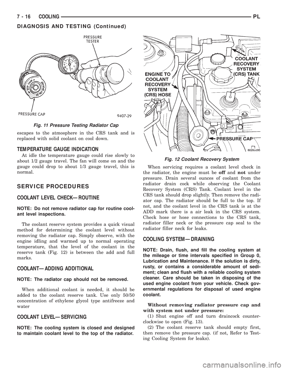
end of radiator pressure tester (Fig. 11). Working the
plunger, increase the pressure to 104 kPa (15 psi) on
the gauge. If the pressure cap fails to hold pressure
of at least 97 kPa (14 psi), replace the cap.
CAUTION: The radiator pressure tester is very sen-
sitive to small air leaks that will not cause cooling
system problems. A pressure cap that does not
have a history of coolant loss should not be
replaced just because it leaks slowly when tested
with this tool. Add water to the tool. Turn the tool
upside down, and recheck the pressure cap to con-
firm that the cap is faulty.
If the pressure cap tests properly while posi-
tioned the on radiator pressure tester, but will not
hold pressure or vacuum when positioned on the
filler neck, inspect the filler neck and cap top gas-
ket for irregularities that may prevent the cap from
sealing properly.
LOW COOLANT LEVEL AERATION
²Will cause corrosion in the system.
²High reading shown on the temperature gauge.
²Air in the coolant will also cause loss of flow
through the heater.
²Exhaust gas leaks into the coolant can also
cause the above problems.
DEAERATION
Air can only be removed from the system by gath-
ering under the pressure cap. On the next heat up it
will be pushed past the pressure cap into the CRS
tank by thermal expansion of the coolant. It thenFig. 10 Cooling System Pressure Cap
PLCOOLING 7 - 15
DIAGNOSIS AND TESTING (Continued)
Page 209 of 1200
escapes to the atmosphere in the CRS tank and is
replaced with solid coolant on cool down.
TEMPERATURE GAUGE INDICATION
At idle the temperature gauge could rise slowly to
about 1/2 gauge travel. The fan will come on and the
gauge could drop to about 1/3 gauge travel, this is
normal.
SERVICE PROCEDURES
COOLANT LEVEL CHECKÐROUTINE
NOTE: Do not remove radiator cap for routine cool-
ant level inspections.
The coolant reserve system provides a quick visual
method for determining the coolant level without
removing the radiator cap. Simply observe, with the
engine idling and warmed up to normal operating
temperature, that the level of the coolant in the
reserve tank (Fig. 12) is between the add and full
marks.
COOLANTÐADDING ADDITIONAL
NOTE: The radiator cap should not be removed.
When additional coolant is needed, it should be
added to the coolant reserve tank. Use only 50/50
concentration of ethylene glycol type antifreeze and
water
COOLANT LEVELÐSERVICING
NOTE: The cooling system is closed and designed
to maintain coolant level to the top of the radiator.When servicing requires a coolant level check in
the radiator, the engine must beoffandnotunder
pressure. Drain several ounces of coolant from the
radiator drain cock while observing the Coolant
Recovery System (CRS) Tank. Coolant level in the
CRS tank should drop slightly. Then remove the radi-
ator cap. The radiator should be full to the top. If
not, and the coolant level in the CRS tank is at the
ADD mark there is a air leak in the CRS system.
Check hose or hose connections to the CRS tank,
radiator filler neck or the pressure cap seal to the
radiator filler neck for leaks.
COOLING SYSTEMÐDRAINING
NOTE: Drain, flush, and fill the cooling system at
the mileage or time intervals specified in Group 0,
Lubrication and Maintenance. If the solution is dirty,
rusty, or contains a considerable amount of sedi-
ment; clean and flush with a reliable cooling system
cleaner. Care should be taken in disposing of the
used engine coolant from your vehicle. Check gov-
ernmental regulations for disposal of used engine
coolant.
Without removing radiator pressure cap and
with system not under pressure:
(1) Shut engine off and turn draincock counter-
clockwise to open (Fig. 13).
(2) The coolant reserve tank should empty first,
then remove the pressure cap. (if not, Refer to Test-
ing Cooling System for leaks).
Fig. 11 Pressure Testing Radiator Cap
Fig. 12 Coolant Recovery System
7 - 16 COOLINGPL
DIAGNOSIS AND TESTING (Continued)
Page 212 of 1200
RADIATOR
REMOVAL
WARNING: DO NOT REMOVE THE CYLINDER
BLOCK PLUG OR THE RADIATOR DRAINCOCK
WITH THE SYSTEM HOT AND UNDER PRESSURE
BECAUSE SERIOUS BURNS FROM COOLANT CAN
OCCUR.
(1) Disconnect negative battery cable from battery.
(2) Drain cooling system. Refer to Cooling System
Draining in this section.
(3) Remove engine air inlet duct.
(4) Remove upper radiator hose from the radiator.
(5) Disconnect and cap automatic transmission
hoses, if equipped.
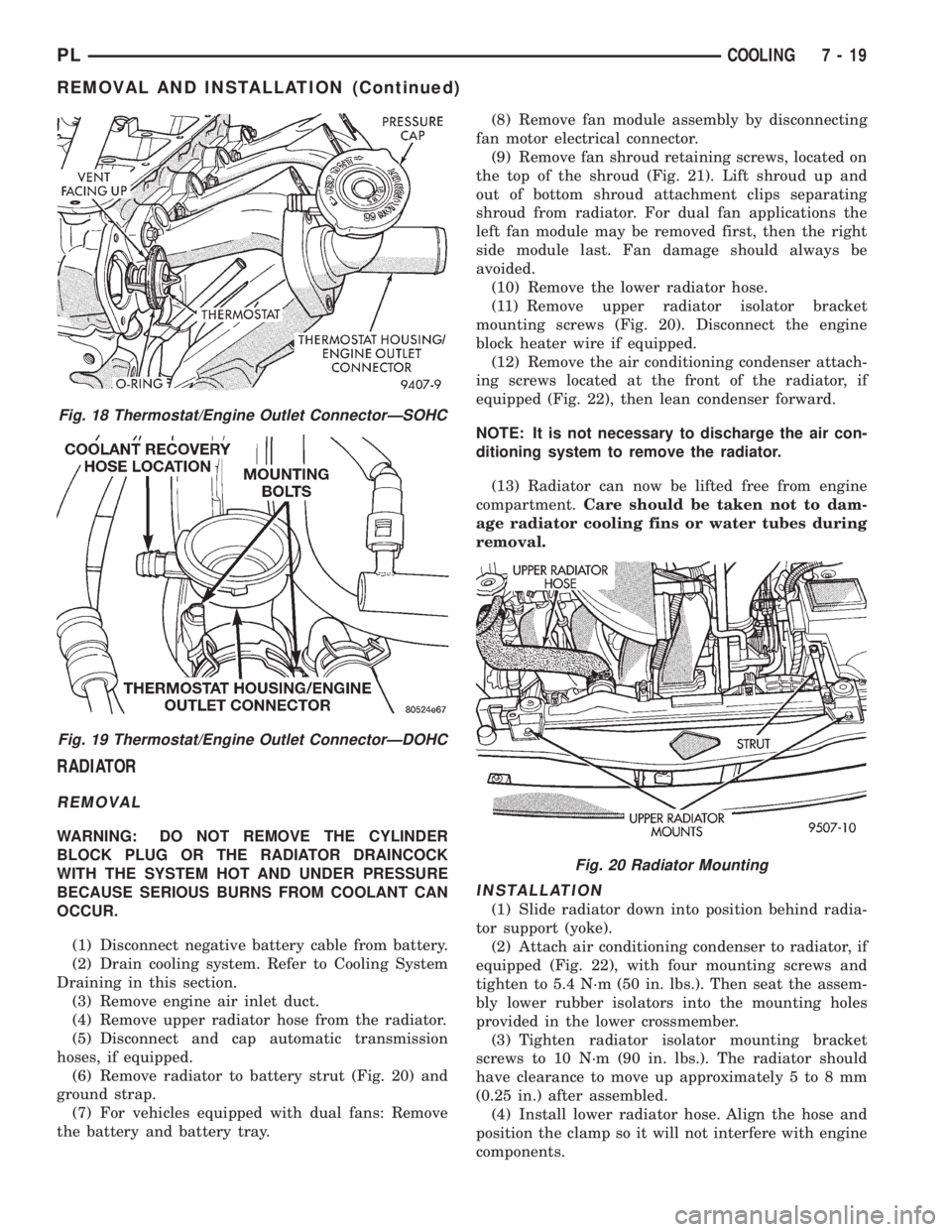
(6) Remove radiator to battery strut (Fig. 20) and
ground strap.
(7) For vehicles equipped with dual fans: Remove
the battery and battery tray.(8) Remove fan module assembly by disconnecting
fan motor electrical connector.
(9) Remove fan shroud retaining screws, located on
the top of the shroud (Fig. 21). Lift shroud up and
out of bottom shroud attachment clips separating
shroud from radiator. For dual fan applications the
left fan module may be removed first, then the right
side module last. Fan damage should always be
avoided.
(10) Remove the lower radiator hose.
(11) Remove upper radiator isolator bracket
mounting screws (Fig. 20). Disconnect the engine
block heater wire if equipped.
(12) Remove the air conditioning condenser attach-
ing screws located at the front of the radiator, if
equipped (Fig. 22), then lean condenser forward.
NOTE: It is not necessary to discharge the air con-
ditioning system to remove the radiator.
(13) Radiator can now be lifted free from engine
compartment.Care should be taken not to dam-
age radiator cooling fins or water tubes during
removal.
INSTALLATION
(1) Slide radiator down into position behind radia-
tor support (yoke).
(2) Attach air conditioning condenser to radiator, if
equipped (Fig. 22), with four mounting screws and
tighten to 5.4 N´m (50 in. lbs.). Then seat the assem-
bly lower rubber isolators into the mounting holes
provided in the lower crossmember.
(3) Tighten radiator isolator mounting bracket
screws to 10 N´m (90 in. lbs.). The radiator should
have clearance to move up approximately 5 to 8 mm
(0.25 in.) after assembled.
(4) Install lower radiator hose. Align the hose and
position the clamp so it will not interfere with engine
components.
Fig. 18 Thermostat/Engine Outlet ConnectorÐSOHC
Fig. 19 Thermostat/Engine Outlet ConnectorÐDOHC
Fig. 20 Radiator Mounting
PLCOOLING 7 - 19
REMOVAL AND INSTALLATION (Continued)
Page 216 of 1200
Cooling System). Run engine with radiator cap
installed until upper radiator hose is hot. Stop
engine and drain water from system. If water is
dirty, fill, run and drain system again until water
runs clear.
RADIATOR FLUSHING
Drain cooling system and remove radiator hoses
from engine. Install suitable flushing gun in radiator
lower hose. Fill radiator with clean water and turn
on air in short blasts.
CAUTION: Internal radiator pressure must not
exceed 138 kPa (20 psi) as damage to radiator may
result. Continue this procedure until water runs
clear.
ENGINE FLUSHING
Drain radiator (see:Cooling System Draining)
and remove hoses from radiator. Remove engine ther-
mostat and reinstall thermostat housing. A gasket
may be needed to seal the housing to cylinder head
because the seal is part of thermostat. Install suit-
able flushing gun to thermostat housing hose. Turn
on water, and when engine is filled, turn on air, but
no higher than 138 kPa (20 psi) in short blasts. Allowengine to fill between blasts of air. Continue this pro-
cedure until water runs clean. Install thermostat and
fill cooling system. Refer to (Cooling System Refill-
ing) for procedure.
REVERSE FLUSHING
Reverse flushing of the cooling system is the forc-
ing of water through the cooling system, using air
pressure in a direction opposite to that of the normal
flow of water. This is only necessary with dirty sys-
tems and evidence of partial plugging.
CHEMICAL CLEANING
One type of corrosion encountered with aluminum
cylinder heads is aluminum hydroxide deposits. Cor-
rosion products are carried to the radiator and depos-
ited when cooled off. They appear as dark grey when
wet and white when dry. This corrosion can be
removed with a two part cleaner (oxalic acid and
neutralizer) available in auto parts outlets. Follow
manufacturers directions for use.
ADJUSTMENTS
PROPER BELT TENSION
Satisfactory performance of the belt driven accesso-
ries depends on belt condition and proper belt ten-
sion. Refer to Accessory Drive Belt Inspection in this
section. There are two belt tensioning methods given
in order of preference:
²Belt tension gauge method.
²Torque equivalent method.
The belt tension gauge method usually requires the
vehicle to be raised on a hoist and the splash shield
removed.
TORQUE EQUIVALENT METHOD
Adjustable accessory brackets provided with a 13
mm (1/2 in.) square hole for a torque wrench can use
an equivalent torque value for belt adjustment.
Equivalent torque values for adjusting these acces-
sory drive belts are specified in the Belt Tension
Chart.
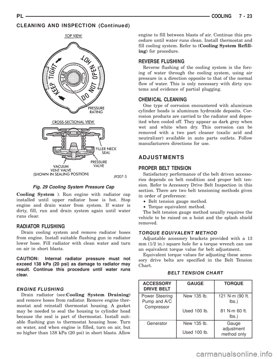
Fig. 29 Cooling System Pressure Cap
BELT TENSION CHART
ACCESSORY
DRIVE BELTGAUGE TORQUE
Power Steering
Pump and A/C
CompressorNew 135 lb. 121 N´m (90 ft.
lbs.)
Used 100 lb. 81 N´m 60 ft.
lbs.)
Generator New 135 lb. Gauge
adjustment
method only Used 100 lb.
PLCOOLING 7 - 23
CLEANING AND INSPECTION (Continued)
Page 217 of 1200
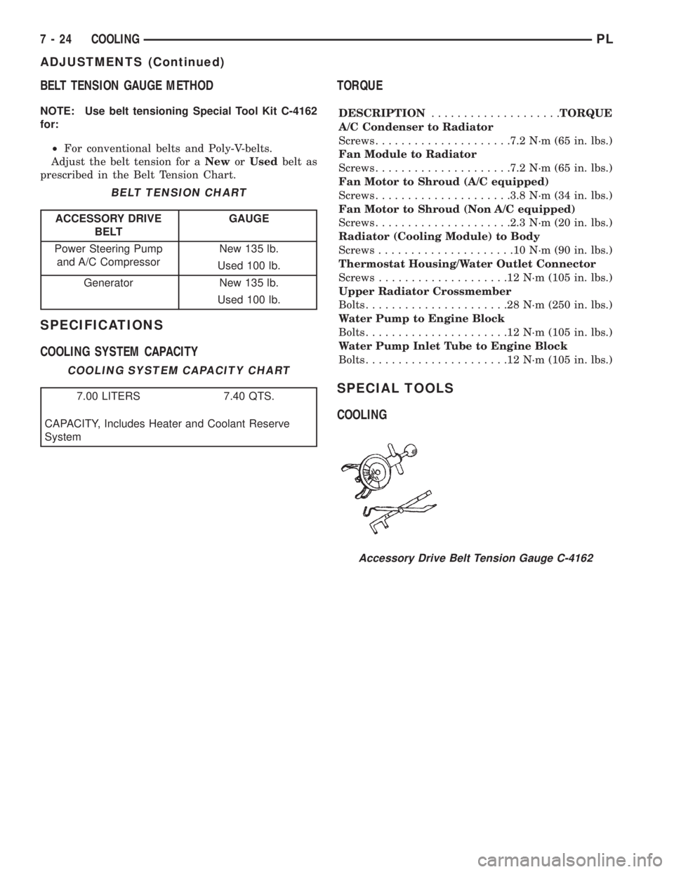
BELT TENSION GAUGE METHOD
NOTE: Use belt tensioning Special Tool Kit C-4162
for:
²For conventional belts and Poly-V-belts.
Adjust the belt tension for aNeworUsedbelt as
prescribed in the Belt Tension Chart.
SPECIFICATIONS
COOLING SYSTEM CAPACITYTORQUE
DESCRIPTION....................TORQUE
A/C Condenser to Radiator
Screws.....................7.2 N´m (65 in. lbs.)
Fan Module to Radiator
Screws.....................7.2 N´m (65 in. lbs.)
Fan Motor to Shroud (A/C equipped)
Screws.....................3.8 N´m (34 in. lbs.)
Fan Motor to Shroud (Non A/C equipped)
Screws.....................2.3 N´m (20 in. lbs.)
Radiator (Cooling Module) to Body
Screws.....................10N´m(90in.lbs.)
Thermostat Housing/Water Outlet Connector
Screws....................12N´m(105 in. lbs.)
Upper Radiator Crossmember
Bolts......................28N´m(250 in. lbs.)
Water Pump to Engine Block
Bolts......................12N´m(105 in. lbs.)
Water Pump Inlet Tube to Engine Block
Bolts......................12N´m(105 in. lbs.)
SPECIAL TOOLS
COOLING
BELT TENSION CHART
ACCESSORY DRIVE
BELTGAUGE
Power Steering Pump
and A/C CompressorNew 135 lb.
Used 100 lb.
Generator New 135 lb.
Used 100 lb.
COOLING SYSTEM CAPACITY CHART
7.00 LITERS 7.40 QTS.
CAPACITY, Includes Heater and Coolant Reserve
System
Accessory Drive Belt Tension Gauge C-4162
7 - 24 COOLINGPL
ADJUSTMENTS (Continued)
Page 227 of 1200
WARNING: TO PROTECT THE HANDS FROM BAT-
TERY ACID, A SUITABLE PAIR OF HEAVY DUTY
RUBBER GLOVES, NOT THE HOUSEHOLD TYPE,
SHOULD BE WORN WHEN REMOVING OR SERVIC-
ING A BATTERY. SAFETY GLASSES ALSO SHOULD
BE WORN.
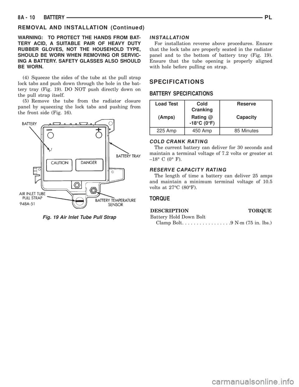
(4) Squeeze the sides of the tube at the pull strap
lock tabs and push down through the hole in the bat-
tery tray (Fig. 19). DO NOT push directly down on
the pull strap itself.
(5) Remove the tube from the radiator closure
panel by squeezing the lock tabs and pushing from
the front side (Fig. 16).INSTALLATION
For installation reverse above procedures. Ensure
that the lock tabs are properly seated in the radiator
panel and to the bottom of battery tray (Fig. 19).
Ensure that the tube opening is properly aligned
with hole before pulling on strap.
SPECIFICATIONS
BATTERY SPECIFICATIONS
COLD CRANK RATING
The current battery can deliver for 30 seconds and
maintain a terminal voltage of 7.2 volts or greater at
±18É C (0É F).
RESERVE CAPACITY RATING
The length of time a battery can deliver 25 amps
and maintain a minimum terminal voltage of 10.5
volts at 27ÉC (80ÉF).
TORQUE
DESCRIPTION TORQUE
Battery Hold Down Bolt
Clamp Bolt.................9N´m(75in.lbs.)
Fig. 19 Air Inlet Tube Pull Strap
Load Test Cold
CrankingReserve
(Amps) Rating @
-18ÉC (0ÉF)Capacity
225 Amp 450 Amp 85 Minutes
8A - 10 BATTERYPL
REMOVAL AND INSTALLATION (Continued)
Page 348 of 1200
LAMP SERVICE
INDEX
page page
GENERAL INFORMATION
HEADLAMP DIMMER SWITCH............... 5
HEADLAMP SWITCH...................... 5
REMOVAL AND INSTALLATION
FOG LAMP.............................. 6HEADLAMP ASSEMBLY.................... 5
HEADLAMP LEVELING MOTOR.............. 6
SIDE REPEATER LAMP.................... 6
GENERAL INFORMATION
HEADLAMP SWITCH
Service procedures for the headlamp switch can be
found in Group 8E, Instrument Panel and Gauges.
More information can be found in Group 8W, Wiring
Diagrams.
HEADLAMP DIMMER SWITCH
The headlamp dimmer switch is incorporated into
the multi-function (turn signal) switch. Proper proce-
dures can be found in Group 8J, Turn Signal and
Flashers. More information can be found in Group
8W, Wiring Diagrams.
REMOVAL AND INSTALLATION
HEADLAMP ASSEMBLY
REMOVAL
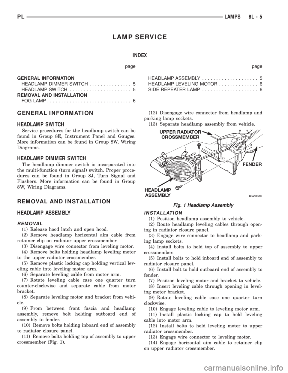
(1) Release hood latch and open hood.
(2) Remove headlamp horizontal aim cable from
retainer clip on radiator upper crossmember.
(3) Disengage wire connector from leveling motor.
(4) Remove bolts holding headlamp leveling motor
to the upper radiator crossmember.
(5) Remove plastic locking cap holding vertical lev-
eling cable into leveling motor arm.
(6) Separate leveling cable from motor arm.
(7) Rotate leveling cable case one quarter turn
counter-clockwise and separate cable from motor
bracket.
(8) Separate leveling motor and bracket from vehi-
cle.
(9) From between front fascia and headlamp
assembly, remove bolt holding outboard end of
assembly to fender.
(10) Remove bolts holding inboard end of assembly
to radiator closure panel.
(11) Remove bolts holding top of assembly to upper
crossmember (Fig. 1).(12) Disengage wire connector from headlamp and
parking lamp sockets.
(13) Separate headlamp assembly from vehicle.
INSTALLATION
(1) Position headlamp assembly to vehicle.
(2) Route headlamp leveling cables through open-
ing in radiator closure panel.
(3) Engage wire connector to headlamp and park-
ing lamp sockets.
(4) Install bolts to hold top of assembly to upper
crossmember.
(5) Install bolts to hold inboard end of assembly to
radiator closure panel.
(6) Install bolt to hold outboard end of assembly to
fender.
(7) Position leveling motor and bracket to vehicle.
(8) Insert leveling cable through opening in level-
ing motor bracket.
(9) Rotate leveling cable case one quarter turn
clockwise.
(10) Engage leveling cable to leveling motor arm.
(11) Install plastic locking cap to hold leveling
cable into motor arm.
(12) Install bolts to hold leveling motor to upper
radiator crossmember.
(13) Engage wire connector to leveling motor.
(14) Engage horizontal aim cable to retainer clip
on upper radiator crossmember.
Fig. 1 Headlamp Assembly
PLLAMPS 8L - 5
Page 349 of 1200
(15) Verify lamp operation.
HEADLAMP LEVELING MOTOR
REMOVAL
(1) Disengage wire connector from headlamp level-
ing motor.
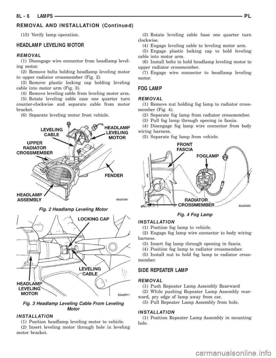
(2) Remove bolts holding headlamp leveling motor
to upper radiator crossmember (Fig. 2).
(3) Remove plastic locking cap holding leveling
cable into motor arm (Fig. 3).
(4) Remove leveling cable from leveling motor arm.
(5) Rotate leveling cable case one quarter turn
counter-clockwise and separate cable from motor
bracket.
(6) Separate leveling motor from vehicle.
INSTALLATION
(1) Position headlamp leveling motor to vehicle.
(2) Insert leveling motor through hole in leveling
motor bracket.(3) Rotate leveling cable base one quarter turn
clockwise.
(4) Engage leveling cable to leveling motor arm.
(5) Engage plastic locking cap to hold leveling
cable into motor arm.
(6) Install bolts to hold headlamp leveling motor to
upper radiator crossmember.
(7) Engage wire connector to headlamp leveling
motor.
FOG LAMP
REMOVAL
(1) Remove nut holding fog lamp to radiator cross-
member (Fig. 4).
(2) Separate fog lamp from radiator crossmember.
(3) Pull fog lamp through opening in fascia.
(4) Disengage fog lamp wire connector from body
wiring harness.
(5) Separate fog lamp from vehicle.
INSTALLATION
(1) Position fog lamp to vehicle.
(2) Engage fog lamp wire connector to body wiring
harness.
(3) Insert fog lamp through opening in fascia.
(4) Position fog lamp to radiator crossmember.
(5) Install nut to hold fog lamp to radiator cross-
member.
SIDE REPEATER LAMP
REMOVAL
(1) Push Repeater Lamp Assembly Rearward
(2) While pushing Repeater Lamp Assembly rear-
ward, pry edge of lamp away from car.
(3) Pull Repeater Lamp Assembly from hole.
INSTALLATION
(1) Position Repeater Lamp Assembly in mounting
hole.
Fig. 2 Headlamp Leveling Motor
Fig. 3 Headlamp Leveling Cable From Leveling
Motor
Fig. 4 Fog Lamp
8L - 6 LAMPSPL
REMOVAL AND INSTALLATION (Continued)