Page 2932 of 3115

REMOVAL
1. REMOVE FRONT WHEEL
Torque: 131 N´m (1,340 kgf´cm")
SA14F-04
F04367
F04368
F05795
A
B
C
F05161
SA-26
- SUSPENSION AND AXLEFRONT DRIVE SHAFT
1976 Author�: Date�:
2004 LAND CRUISER (RM1071U)
REMOVAL
1. REMOVE FRONT WHEEL
Torque: 131 N´m (1,340 kgf´cm, 97 ft´lbf)
2. REMOVE BRAKE CALIPER
(a) Remove the bolt and disconnect the flexible hose from
the steering knuckle.
Torque: 28 N´m (290 kgf´cm, 21 ft´lbf)
(b) Remove the 2 bolts, washers and brake caliper.
Torque: 123 N´m (1,250 kgf´cm, 91 ft´lbf)
(c) Support the brake caliper securely.
3. REMOVE SNAP RING
(a) Using a screwdriver and hammer, remove the grease cap
from the flange.
(b) Using snap ring pliers, remove the snap ring.
4. DISCONNECT ABS SPEED SENSOR AND WIRE HAR-
NESS
Remove the 3 bolts and disconnect the ABS speed sensor and
wire harness.
Torque:
A: 8.0 N´m (82 kgf´cm, 71 in.´lbf)
B: 13 N´m (130 kgf´cm, 10 ft´lbf)
C: 28 N´m (290 kgf´cm, 21 ft´lbf)
5. DISCONNECT STEERING KNUCKLE ARM
Remove the 2 bolts and disconnect the steering knuckle arm.
Torque: 147 N´m (1,500 kgf´cm, 108 ft´lbf)
HINT:
At the time of installation, please refer to the following items.
�Clean the threads of the 2 bolts and steering knuckle with
toluene or trichloroethylene.
Page 2940 of 3115

REMOVAL
1. REMOVE FRONT WHEEL
Torque: 131 N´m (1,340")
SA155-02
F04381
F04382
F04383
SST
F04384
- SUSPENSION AND AXLEFRONT LOWER SUSPENSION ARM
SA-75
2025 Author�: Date�:
2004 LAND CRUISER (RM1071U)
REMOVAL
1. REMOVE FRONT WHEEL
Torque: 131 N´m (1,340 kgf´cm, 97 ft´lbf)
2. REMOVE ENGINE UNDER COVER
3. REMOVE FRONT TORSION BAR SPRING
(See page SA-66)
4. DISCONNECT STABILIZER BAR LINK FROM LOWER
SUSPENSION ARM
Remove the bolt and disconnect the stabilizer bar link from the
lower suspension arm.
Torque: 52 N´m (530 kgf´cm, 38 ft´lbf)
5. DISCONNECT SHOCK ABSORBER FROM LOWER
SUSPENSION ARM
Remove the nut, bolt and disconnect the shock absorber from
the lower suspension arm.
Torque: 135 N´m (1,400 kgf´cm, 100 ft´lbf)
6. DISCONNECT STEERING KNUCKLE FROM LOWER
SUSPENSION ARM
(a) Remove the cotter pin and nut.
Torque: 159 N´m (1,625 kgf´cm, 117 ft´lbf)
(b) Using SST, disconnect the steering knuckle from the low-
er suspension arm.
SST 09628-6201 1
7. REMOVE LOWER SUSPENSION ARM
Remove the 2 nuts, 3 bolts and lower suspension arm.
Torque: 230 N´m (2,350 kgf´cm, 170 ft´lbf)
Page 2947 of 3115
SA14S-02
F04382
F04407
- SUSPENSION AND AXLEFRONT SHOCK ABSORBER
SA-61
2011 Author�: Date�:
2004 LAND CRUISER (RM1071U)
REMOVAL
1. REMOVE FRONT WHEEL
Torque: 131 N´m (1,340 kgf´cm, 97 ft´lbf)
2. REMOVE FRONT FENDER APRON
3. REMOVE SHOCK ABSORBER
(a) Remove the bolt, nut and disconnect the shock absorber
from the lower suspension arm.
Torque: 135 N´m (1,400 kgf´cm, 100 ft´lbf)
(b) While holding the piston rod, remove the nut, cushion, re-
tainer and shock absorber.
Torque: 68 N´m (700 kgf´cm, 50 ft´lbf)
(c) Remove the cushion and retainer from the shock absorb-
er.
Page 2953 of 3115
F05246
A SA-68
- SUSPENSION AND AXLEFRONT TORSION BAR SPRING
2018 Author�: Date�:
2004 LAND CRUISER (RM1071U)
(1) Align matchmarks on the torsion bar spring and an-
chor arm and install them.
(2) Align matchmarks on the torsion bar spring and
torque arm and install them.
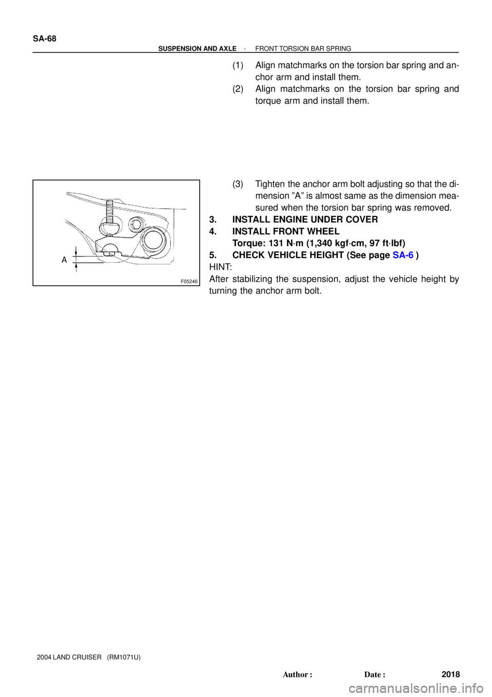
(3) Tighten the anchor arm bolt adjusting so that the di-
mension ºAº is almost same as the dimension mea-
sured when the torsion bar spring was removed.
3. INSTALL ENGINE UNDER COVER
4. INSTALL FRONT WHEEL
Torque: 131 N´m (1,340 kgf´cm, 97 ft´lbf)
5. CHECK VEHICLE HEIGHT (See page SA-6)
HINT:
After stabilizing the suspension, adjust the vehicle height by
turning the anchor arm bolt.
Page 2954 of 3115
SA14X-02
F05247
Matchmarks
F05246
A
F05245
B SA-66
- SUSPENSION AND AXLEFRONT TORSION BAR SPRING
2016 Author�: Date�:
2004 LAND CRUISER (RM1071U)
REMOVAL
1. REMOVE FRONT WHEEL
2. REMOVE ENGINE UNDER COVER
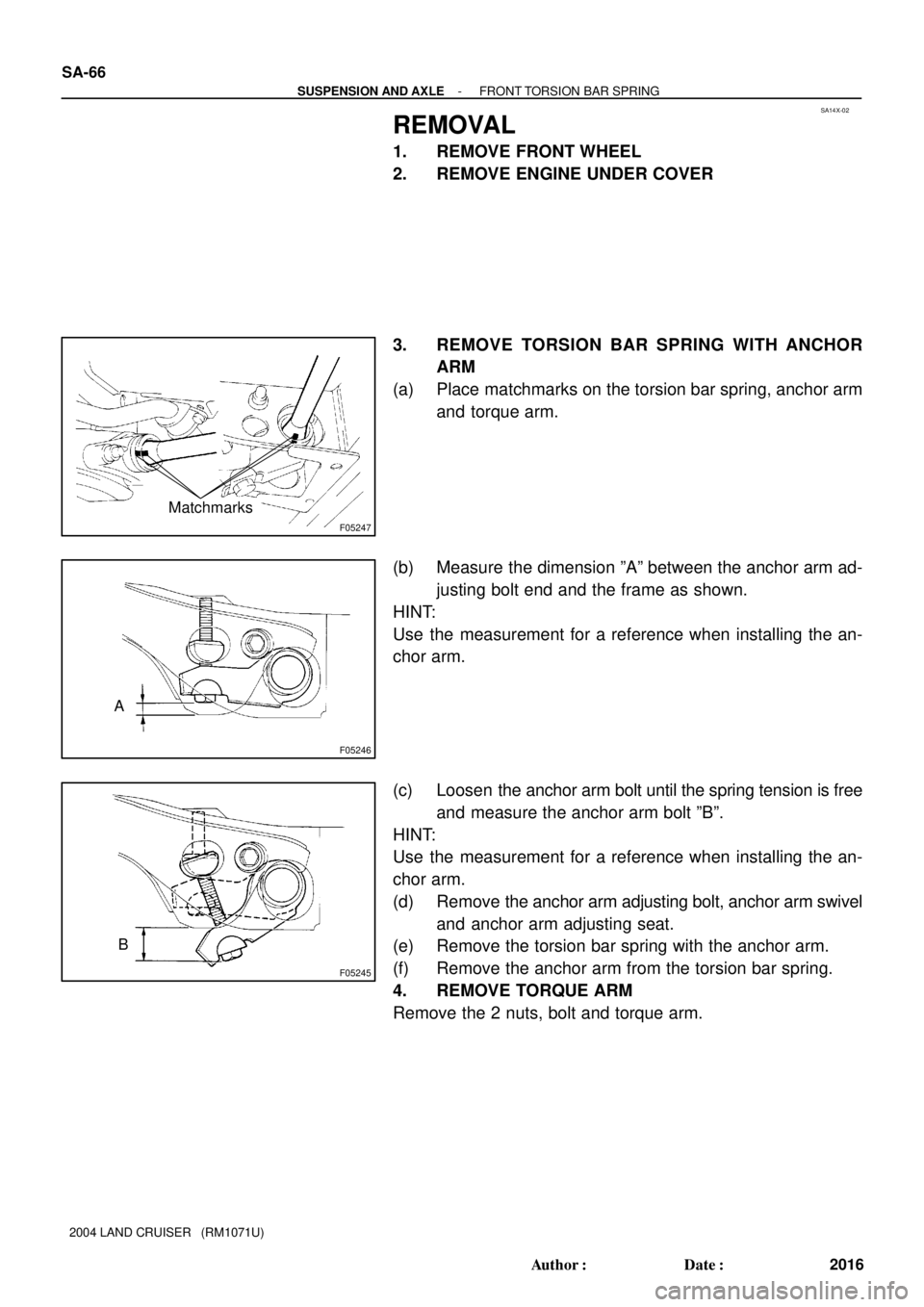
3. REMOVE TORSION BAR SPRING WITH ANCHOR
ARM
(a) Place matchmarks on the torsion bar spring, anchor arm
and torque arm.
(b) Measure the dimension ºAº between the anchor arm ad-
justing bolt end and the frame as shown.
HINT:
Use the measurement for a reference when installing the an-
chor arm.
(c) Loosen the anchor arm bolt until the spring tension is free
and measure the anchor arm bolt ºBº.
HINT:
Use the measurement for a reference when installing the an-
chor arm.
(d) Remove the anchor arm adjusting bolt, anchor arm swivel
and anchor arm adjusting seat.
(e) Remove the torsion bar spring with the anchor arm.
(f) Remove the anchor arm from the torsion bar spring.
4. REMOVE TORQUE ARM
Remove the 2 nuts, bolt and torque arm.
Page 2958 of 3115

REMOVAL
1. REMOVE FRONT WHEEL
Torque: 131 N´m (1,")
SA150-02
F04377
F04378
SST
F04379
Matchmarks
SA-70
- SUSPENSION AND AXLEFRONT UPPER SUSPENSION ARM
2020 Author�: Date�:
2004 LAND CRUISER (RM1071U)
REMOVAL
1. REMOVE FRONT WHEEL
Torque: 131 N´m (1,340 kgf´cm, 97 ft´lbf)
2. REMOVE FRONT FENDER APRON
3. DISCONNECT ABS SPEED SENSOR WIRE HARNESS
Remove the 2 bolts and disconnect the ABS speed sensor wire
harness.
Torque: 13 N´m (130 kgf´cm, 10 ft´lbf)
4. DISCONNECT STEERING KNUCKLE FROM UPPER
SUSPENSION ARM
(a) Support the lower suspension arm with a jack.
(b) Remove the cotter pin and nut.
Torque: 110 N´m (1,125 kgf´cm, 81 ft´lbf)
HINT:
At the time of installation, if the holes for the cotter pin are not
aligned, tighten the nut further up to 60°.
(c) Using SST, disconnect the steering knuckle from the up-
per suspension arm.
SST 09628-6201 1
5. REMOVE UPPER SUSPENSION ARM
(a) Place matchmarks on the front and rear No. 2 adjust cams
and body.
(b) Remove the 2 nuts, No. 1 and No. 2 camber adjust cams
and upper suspension arm.
Torque: 98 N´m (1,000 kgf´cm, 72 ft´lbf)
HINT:
At the time of installation, after stabilizing the suspension,
torque the nuts.
Page 2964 of 3115
SA0028
AB
FrontBA
A: Inside
B: Outside
F05200
SA-10
- SUSPENSION AND AXLEFRONT WHEEL ALIGNMENT
1960 Author�: Date�:
2004 LAND CRUISER (RM1071U)
7. INSPECT AND ADJUST WHEEL ANGLE
(a) Turn the steering wheel fully, and measure the turning
angle.
Wheel turning angle:
Inside wheel36°42' (33°42' - 36°42')
36.7° (33.7° - 36.7°)
Outside wheel: Reference32°36'
32.6°
If the right and left inside wheel angles differ from the specified
value, check the right and left rack end lengths.
(b) When toe-in is normal after inspection, adjust wheel
angle with the knuckle stopper bolt of the lower suspen-
sion arm.
Torque: 44 N´m (450 kgf´cm, 32 ft´lbf)
Page 2965 of 3115
SA148-04
F04340Matchmarks
F04344
F04345
F04340Matchmarks
SA-18
- SUSPENSION AND AXLEFRONT WHEEL HUB BOLT
1968 Author�: Date�:
2004 LAND CRUISER (RM1071U)
FRONT WHEEL HUB BOLT
REPLACEMENT
1. REMOVE FRONT AXLE HUB (See page SA-12)
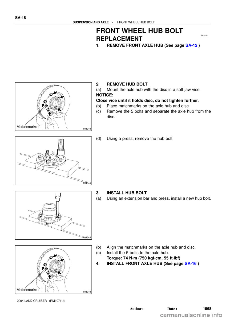
2. REMOVE HUB BOLT
(a) Mount the axle hub with the disc in a soft jaw vice.
NOTICE:
Close vice until it holds disc, do not tighten further.
(b) Place matchmarks on the axle hub and disc.
(c) Remove the 5 bolts and separate the axle hub from the
disc.
(d) Using a press, remove the hub bolt.
3. INSTALL HUB BOLT
(a) Using an extension bar and press, install a new hub bolt.
(b) Align the matchmarks on the axle hub and disc.
(c) Install the 5 bolts to the axle hub.
Torque: 74 N´m (750 kgf´cm, 55 ft´lbf)
4. INSTALL FRONT AXLE HUB (See page SA-16)