Page 417 of 3115

H20954
H20955
: 2 Clips
H18913
H18912
: 6 Clips BO-92
- BODYINSTRUMENT PANEL
2666 Author�: Date�:
2004 LAND CRUISER (RM1071U)
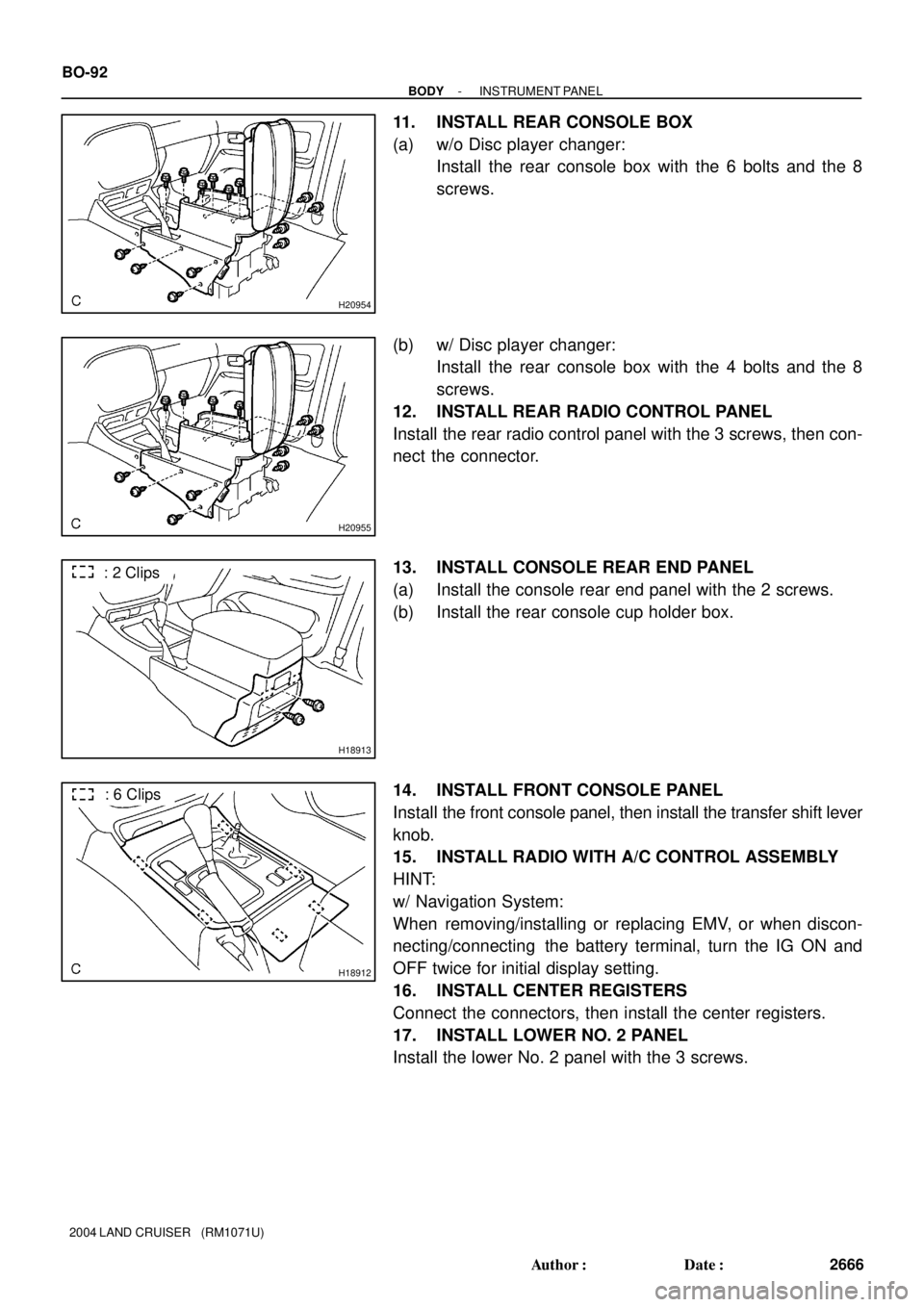
11. INSTALL REAR CONSOLE BOX
(a) w/o Disc player changer:
Install the rear console box with the 6 bolts and the 8
screws.
(b) w/ Disc player changer:
Install the rear console box with the 4 bolts and the 8
screws.
12. INSTALL REAR RADIO CONTROL PANEL
Install the rear radio control panel with the 3 screws, then con-
nect the connector.
13. INSTALL CONSOLE REAR END PANEL
(a) Install the console rear end panel with the 2 screws.
(b) Install the rear console cup holder box.
14. INSTALL FRONT CONSOLE PANEL
Install the front console panel, then install the transfer shift lever
knob.
15. INSTALL RADIO WITH A/C CONTROL ASSEMBLY
HINT:
w/ Navigation System:
When removing/installing or replacing EMV, or when discon-
necting/connecting the battery terminal, turn the IG ON and
OFF twice for initial display setting.
16. INSTALL CENTER REGISTERS
Connect the connectors, then install the center registers.
17. INSTALL LOWER NO. 2 PANEL
Install the lower No. 2 panel with the 3 screws.
Page 826 of 3115
F17777F18531
ABS & BA & TRAC
& VSC ECU
S5
Stop Light SW
F16
Fl Block
H11
High Mounted
Stop Light STOP
R12
Rear Combination
Light RHSTP A4210
G-W
2B 23
2K 35
2D 35
2D31
2C
B-G1
ALT
J/B No.21 G-W
21
G-R
BP38
G-W
BH22
G-W
21W-B
BH2 5
W-B
BP3
6 3 5 G-W
G-W
BQ23
G-W G-W
31W-B
W-B
BQ2 10
G-W
31
W-B
BJ BM
BJ BK 3 5 BL48
G-W
BD27 G-W
W-B
W-B
W-B
W-BW-B
W-B G-W
BatteryR13
Rear Combination
Light RHR10
Rear Combination
Light LH
R11
Rear Combination Light LH
G-WCowl Side J/B LH
G-WG-W
W-B
3BH2
(*2)
(*1)
*1: w/ Navigation System
*2: w/o Navigation System DI-574
- DIAGNOSTICSABS & VEHICLE STABILITY CONTROL (VSC) &
BRAKE ASSIST (BA) SYSTEM
767 Author�: Date�:
2004 LAND CRUISER (RM1071U)
WIRING DIAGRAM
Page 1328 of 3115
A21771
S5 Stop Light SWECM
ST1-
STP J/B No. 4
Cowl Side J/B RH
IGN J4
J/C I18
Ignition SW
Cowl Side J/B LH
STOP
Engine Room J/B
FL BlockH11
High Mounted Stop Light
R10
Rear Combination Light LH
R13
Rear Combination Light RHStop
Stop
MAINAM2
J/B No. 2ALT
BatteryBK BJBM 1
32
413
4E
4E 159
4C
4D9E812
E819 8
3E
3E4
4
3M3M5 A A
6 7
35
35
31 4126
2D 2E
2E
2D2K
10
2A
1
2C
1
1C9
1B
2
F15
1
F1682
BP3BH2
2
1
5BH2
BP3
6 53
78
BD2 BL4
35 G-W
G-R
R-G
B-R
B-R B-R
W-R
G-W
W-R
G-RW-R G-W
G-W G-W G-W
W-B G-W G-WB-R R-G
B-G
B-G
W-R
G-W
G-W G-W
G-W
G-WW-B
W-B
W-B
W-B W-BW-BW-B AM2 IG2
*1: w/o Navigation System
*2: w/ Navigation System
(*1)
BH2 3(*2)
- DIAGNOSTICSENGINE
DI-279
472 Author�: Date�:
2004 LAND CRUISER (RM1071U)
WIRING DIAGRAM
Page 1741 of 3115
I27345
Cowl Side J/B RH
76
3Q
IND 25
G-RT5
Theft Deterrent ECU
12
3D
G-R 21
M5 14
M9
3
M5 8
M9 (*2)(*1)
(*2) (*1) SECURITY (*2) LP (*1)
GND (*2) GND1 (*1) Multi Display
Cowl Side J/B RHW-B
8
3D
10
3D
W-B W-BH
H HJ10
J/C
II
*1: w/ Navigation system
*2: w/o Navigation system
- DIAGNOSTICSTHEFT DETERRENT SYSTEM
DI-969
1162 Author�: Date�:
2004 LAND CRUISER (RM1071U)
Security indicator circuit
CIRCUIT DESCRIPTION
When the theft deterrent system is preparing to be set, this circuit lights up the indicator.
When the system is set, the indicator blinks.
It also indicates the condition of the immobiliser system according to the request from the Transponder Key
ECU.
WIRING DIAGRAM
DIB4T-02
Page 1742 of 3115
I24677
IND
(+) (-)
DI-970
- DIAGNOSTICSTHEFT DETERRENT SYSTEM
1163 Author�: Date�:
2004 LAND CRUISER (RM1071U)
INSPECTION PROCEDURE
HINT:
In case of using the hand-held tester, start the inspection from step 1 and in case of not using the hand-held
tester, start from step 2.
1 Check security indicator using hand-held tester.
PREPARATION:
Connect the hand-held tester to the DLC 3.
CHECK:
Check that the theft deterrent in the indicator lights in ACTIVE TEST (See page DI-955).
OK Proceed to next circuit inspection shown in
problem symptoms table (See page DI-965).
NG
2 Check security indicator.
CHECK:
Connect the positive lead from the battery to terminal 7 (14) and
negative lead to terminal 6 (8), and check that the warning light
lights up.
( ): w/o Navigation system
OK:
Indicator light lights up.
NG Replace multi-display.
OK
Page 1953 of 3115

2004 LAND CRUISER (EWD548U)
72G ELECTRICAL WIRING ROUTING
Position of Parts in Body
A 32 A/C Amplifier (Rear)
A 33 A/C Amplifier (Rear)
A 34 A/C Amplifier (Rear)
A 35 ABS Speed Sensor Rear LH
A 36 ABS Speed Sensor Rear RH
B 2 Back Door Courtesy SW
B 3 Back Door Key Lock and Unlock SW
B 4 Back Door Lock Motor
Back Door Unlock Detection SW
C 29 Curtain Shield Airbag Squib LH
C 30 Curtain Shield Airbag Squib RH
D 10 Door Courtesy Light Front LH
D 11 Door Courtesy Light Front RH
D 12 Door Courtesy Light Rear LH
D 13 Door Courtesy Light Rear RH
D 14 Door Courtesy SW Front LH
D 15 Door Courtesy SW Front RH
D 16 Door Courtesy SW Rear LH
D 17 Door Courtesy SW Rear RH
D 18 Door Key Lock and Unlock SW LH
D 19 Door Key Lock and Unlock SW RH
D 20 Door Lock Control SW RH
D 21 Door Lock Motor Front LH
Door Unlock Detection SW Front LH
D 22 Door Lock Motor Front RH
Door Unlock Detection SW Front RH
D 23 Door Lock Motor Rear LH
Door Unlock Detection SW Rear LH
D 24 Door Lock Motor Rear RH
Door Unlock Detection SW Rear RH
D 27 Door Control ReceiverF 8 Front Door Speaker LH
F 9 Front Door Speaker RH
F 10 Front Interior Light
Rear Personal Light
F 11 Front Personal Light
F 12 Fuel Pump
Fuel Sender
H 11 High Mounted Stop Light
I 22 Inner Mirror
J 22 Junction Connector
J 23 Junction Connector
J 25 Junction Connector
J 26 Junction Connector
L 1 License Plate Light LH
L 2 License Plate Light RH
M 2 Moon Roof Control ECU
M 3 Moon Roof Control SW
N 2 Navigation ECU
N 3 Navigation ECU
N 4 Navigation ECU
O 5 Overhead J/B
Page 1962 of 3115

2004 LAND CRUISER (EWD548U)
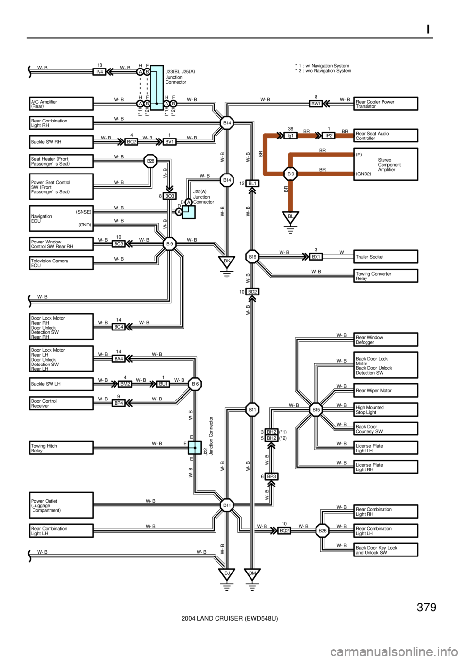
379I
W- B
W- B 10
W- B A/C Amplifier
(
Rear)
Rear Combination
Light RH
Buckle SW RH
Seat Heater (
Fr ont
Passenger' s Seat)
Power Seat Control
SW (
Front
Passenger' s Seat)
Door Lock Motor
Rear RH
Door Unlock
Detection SW
Rear RHTrailer Socket
Rear Combination
Light RH
Rear Combination
Light LH
Back Door Key Lock
and Unlock SW Rear Window
Defogger
Back Door Lock
Motor
Back Door Unlock
Detection SW
Rear Wiper Motor
High Mounted
Stop Light
Back Door
Courtesy SW
License Plate
Light LH
License Plate
Light RH
Power Outlet
(
Luggage
Compartment)
Rear Combination
Light LHB28
B 9 BO3 8
BK B14
B16 BL1 12
B26 BH2 5 BD2 10
BMBP3 6 W- B
W- B
W- B
BQ2 W- B
W- B
W- B
W- B
W- B
W- B
W- B
W- B
W- B
W- BW- B
W- B
W- B W- B
W- B
W- B W- BW- B W- BW- B
W- B W- B
B11Towing Converter
Relay W- B Navigation
ECUW- B
Power Window
Control SW Rear RHW- B
BC310
W- BBW18
W- B W- B W- B
BO24
BV11
W- B W- BW- B IV418
W- B
W- B
BC414
W- B W- BW W- B
BX13
B15 Door Control
Receiver Buckle SW LH Door Lock Motor
Rear LH
Door Unlock
Detection SW
Rear LHBA414
BP49BM24
BU11
B 6
B11 W- B
W- B
W- BW- B
W- B W- B
W- B
W- B
W- B
W- B
BJ
W- BW- B W- B
BR
BR BR 36
Ig11
IP2Rear Seat Audio
Controller
BR
BR BR
B 9Stereo
Component
Amplifier (
E)
BL(
GN D2)
E E
W- B
W- B
Rear Cooler Power
Transistor
W- B B14
J25(
A)
Junction
Connector
W- B
(
SNSE)
(
GND)W- BW- B BF
A H
BF
A H
A H
BF Junction
Connector J23(
B)
, J25(
A)
(
*1)
(
*2) (
*1)
(
*2)
Television Camera
ECUW- B
Junction Connector J22
Towing Hitch
RelayW- B EBH2 3(
*1)
(
*2)* 2 : w/o Navigation System * 1 : w/ Navigation System
A DA D
Page 1972 of 3115

2004 LAND CRUISER (EWD548U)
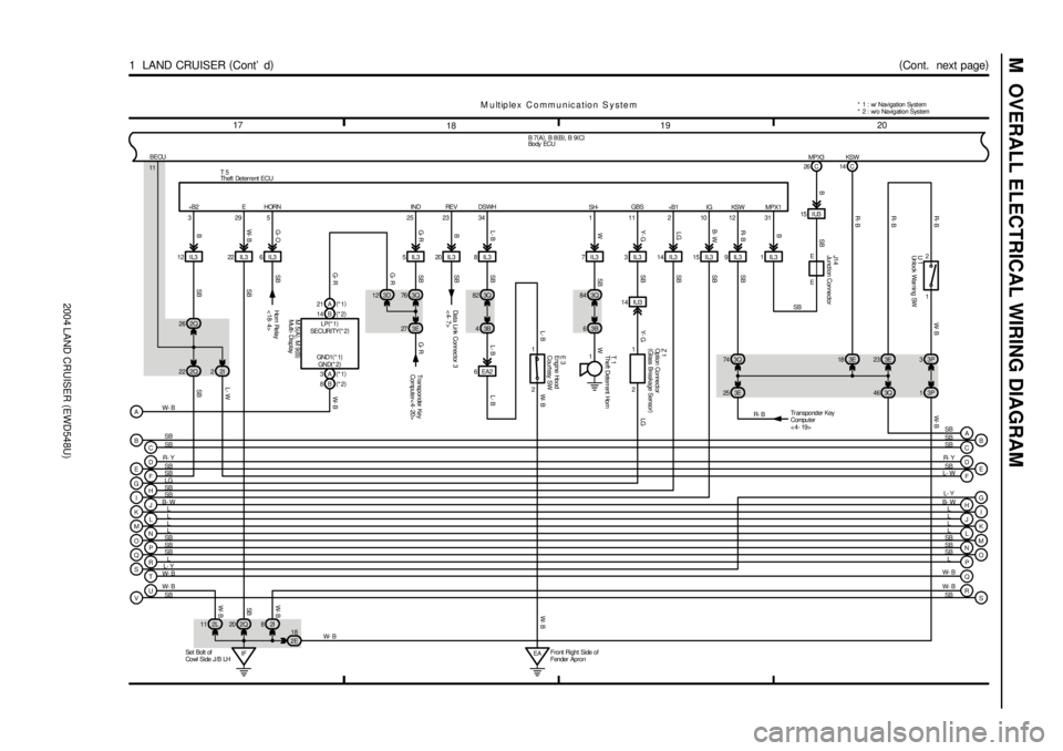
M OVERALL ELECTRICAL WIRING DIAGRAM
1920
18 17
(
Cont. next page)
1 LAND CRUISER (
Cont' d)
1
T 1
114 C
21026 C
1 2
U 1
SH-WSB
KSW +B1 IG MPX1KSW MPX3
R- B
BR- B R- B W- B
T 5
QP ON ML KJ IH GF EDR- Y
SB
SB
LG
SB
B- W
L
L
L
L
SB
SB
SBB 7(
A)
, B 8(
B)
, B 9(
C)
M u ltip le x C o m m u n ic a tio n S y s te m
E
F
I
J
K
M
N
O
P L SB
L- W
L
L
L
SB
SB
SB
SRL
L- Y
Q W- B
TW- B
R
S W- B
SB
SB
SB
J14
E
E 1IL315 I U3
3E 18 3E23
SB
G
H
L D
B- WL- Y R- Y
L
IF Se t Bol t of
Cowl Side J /B LH2Q 20 2L 11 2I83P 3
3P 1 22 IL3
VUW- B
SB12 IL3
2Q 222Q 26
2I 28IL3
3Q 82
3B 4
18
2E 6IL3
6 EA2
2 1 5IL3
EAFront Right Side of
Fender Apron7IL3
3B 63Q 843IL3
14 IU314 IL3 15 IL3 9 IL3 20 IL3
3Q 74
3E 2531 12 11 34 23 25 5 29 3
2 1 GBS DSWH RE V IND HORN E +B 2
W- BR- B
B W- BG- OG- RB L- B Y- GLG B- WR- BB
SB Y- G LG SB
SB SB
W
SB L- B L- BW- B
SB
SB
SB
SB SB
SB L- W
W- BSB W- B W- B
BECU
11
Ho r n Re la y
<18- 4> Data Link Connec tor 3
<4- 7>E 3
W- B
Transponder Key
Computer
<4- 19>
Z 1
L- B
C B
CB
SB SB
SB SB 3Q 76
3E 27 3D 12
14 B(
*2) 21 A(
*1)
3A(
*1)
8B(
*2)
A
Transponder Key
Computer< 4- 20>
G- RG- R
G- R W- B
LP(
*1)
SECURITY(
*2)
GND(
*2) GND1(
*1)
M 5(
A)
, M 9(
B)
W- B* 1 : w/ Nav igation Sy st em
* 2 : w/o Navigation System
3Q 46
A SB
Engine Hood
Courtesy SW
Multi- DisplayTheft Deterrent Horn
Theft Deterrent ECU
Un lo ck War ni ng SW
Bo dy ECU
Junct ion Connector
Option Connect or
(
Glass Breakage Sensor)