Page 198 of 3115
CD Player SOUND JUMPS
19
Radio assembly faulty. Does sound jump only during strong vibration?
Is CD player properly installed?
Functions OK if different CD inserted?
Has sudden temperature change occurred inside cabin?Jumping caused by vibration.
Install properly.
CD faulty.
Formation of condensation due to
temp. changes. Ye sYe s
Ye s
Ye s No No
No
No
20 CD Player SOUND QUALITY POOR (VOLUME FAINT)
Is radio operating normally?CD faulty. Function OK if different CD inserted?
Speaker faulty. Temporarily install another speaker.
Functions OK?Ye s
No
Is speaker property installed?Radio assembly faulty.
Install properly. Ye s
Ye s Ye s No
NoNo
Radio assembly or power amplifier faulty. BE-162
- BODY ELECTRICALAUDIO SYSTEM
2535 Author�: Date�:
2004 LAND CRUISER (RM1071U)
Page 199 of 3115
Radio assembly faulty.
Power amplifier faulty.
Recheck system after repair. Temporarily install another speaker.
Function OK?21 CD Player ANY SPEAKER DOES NOT WORK
Speaker wire harness faulty.
Speaker faulty. Is hiss noise produced by non-functioning speaker?
Does continuity exist in speaker wire harness? Is radio operating normally?
Ye sYe s
Ye s
Ye s No
No
NoNoRadio assembly faulty.
Recheck system after repair.
22 CD Player CD WILL NOT BE EJECTED
Is auto search button of radio
operating normally?
NoRadio assemblyfaulty.
Replace fuse.
+B wire harness faulty.
Radio assembly faulty. Check if RADIO fuse is OK?
No Ye s
NG
OK
Ye s
Is power supplied to +B terminal of radio receiver?
- BODY ELECTRICALAUDIO SYSTEM
BE-163
2536 Author�: Date�:
2004 LAND CRUISER (RM1071U)
Page 200 of 3115
23 Power Amplifier NO POWER COMING IN
+ B wire harness faulty.
GND faulty.
Speaker wire harness faulty. Is tape player operating normally?
Check if ACC fuse is OK?Ye s
NG
No OK No
No
No OK
OK Ye s
Ye s
Ye sNG
NG Check if AMP fuse is OK?Replace fuse.
ACC wire harness faulty. Radio assembly faulty.
Replace fuse.
Check if GND (wire harness side) of power amplifier
grounded normally?Is power supplied to ACC terminal of power amplifier?
Is power supplied to +B terminal of power amplifier?
Does continuity exist in speaker wire harness.
Temporarity install another speaker functions OK?
Power amplifier faulty.
Speaker faulty.
NoYe s BE-164
- BODY ELECTRICALAUDIO SYSTEM
2537 Author�: Date�:
2004 LAND CRUISER (RM1071U)
Page 201 of 3115

24 Power AmplifierPOWER COMIMG IN, BUT WOOFER (POWER) AMPLIFIER NOT
OPERATING
+ B wire harness faulty.
GND faulty.
ACC wire harness faulty.
Speaker wire harness faulty. GND faulty. Is tape player operating normally?
Check if ACC fuse is OK?Ye s
NG
No OK No
No
No
No OK
OK
OK Ye s
Ye s
Ye s
Ye sNG
NG
NG Check if RADIO, AMP fuse is OK?
Radio assembly faulty. Recheck system after repair.Replace fuse.
ACC wire harness faulty. Radio assembly faulty.
Replace fuse.
Is there continuity in speaker wire harness?
Temporarily install another speaker. Functions OK?
Hiss noise from speaker?Ye s
Ye s NoNo
No Ye s+B wire harness faulty.
Power amplifier faulty.
Recheck system after repair. Speaker faulty.
Is power supplied to ACC terminal of power amplifier?
Check if GND (wire harness side) of power amplifier
grounded normally? Is power supplied to +B terminal of power amplifier?
Is power supplied to ACC terminal of radio assembly?
Is power supplied to +B terminal of radio assembly?
Check if GND (wire harness side) of radio assembly
grounded normally?
- BODY ELECTRICALAUDIO SYSTEM
BE-165
2538 Author�: Date�:
2004 LAND CRUISER (RM1071U)
Page 206 of 3115

BE01I-05
- BODY ELECTRICALBODY ELECTRICAL SYSTEM
BE-1
2374 Author�: Date�:
2004 LAND CRUISER (RM1071U)
BODY ELECTRICAL SYSTEM
PRECAUTION
HINT:
Take care to observe the following precautions when performing inspections or removal and replacement
of body electrical related parts.
1. HEADLIGHT SYSTEM
Halogen bulbs have pressurized gas inside and require special handling. They can burst if scratched or
dropped. Hold a bulb only by its plastic or metal case. Don't touch the glass part of a bulb with bare hands.
2. SRS (SUPPLEMENTAL RESTRAINT SYSTEM)
The LAND CRUISER is equipped with an SRS (Supplemental Restraint System) such as the driver airbag
and front passenger airbag. Failure to carry out service operation in the correct sequence could cause the
SRS to unexpectedly deploy during servicing, possibly leading to a serious accident. Before servicing (in-
cluding removal or installation of parts, inspection or replacement), be sure to read the precautionary notices
in the RS section.
3. AUDIO SYSTEM
�If the negative (-) terminal cable is disconnected from the battery, the preset AM, FM 1 and FM 2 sta-
tions stored in memory are erased, so be sure to note the stations and reset them after the negative
(-) terminal cable is reconnected to the battery.
�If the negative (-) terminal cable is disconnected from the battery, the ºANTI-THEFT SYSTEMº will
operate when the cable is reconnected, but the radio, tape player and CD player will not operate. Be
sure to input the correct ID number so that the radio, tape player and CD player can be operated again.
4. MOBILE COMMUNICATION SYSTEM
If the vehicle is equipped with a mobile communication system, refer to precautions in the IN section.
Page 412 of 3115

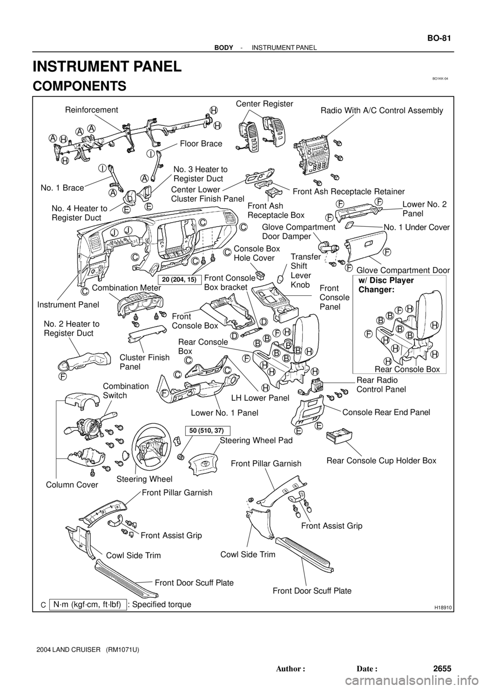
BO1KK-04
H18910
Reinforcement
Floor Brace
No. 1 BraceNo. 3 Heater to
Register Duct
Instrument PanelCenter Register
Radio With A/C Control Assembly
Front Ash Receptacle Retainer Center Lower
Cluster Finish Panel
Front Ash
Receptacle BoxLower No. 2
Panel
Glove Compartment Door
Rear Console Cup Holder Box Front
Console
Panel
Front
Console Box
Rear Console
Box
Rear Radio
Control Panel
Console Rear End Panel Combination Meter
Cluster Finish
Panel
LH Lower Panel
Lower No. 1 Panel No. 2 Heater to
Register Duct
Combination
Switch
Steering WheelSteering Wheel Pad
Front Pillar Garnish
Cowl Side Trim
Front Door Scuff Plate Front Assist Grip No. 4 Heater to
Register Duct
Front Pillar Garnish
Front Assist Grip
Cowl Side Trim
Front Door Scuff Plate
AA
A
A
BBB
C
C
C
C
CC
C
C
C
D
H
A
F
20 (204, 15)
EE
Glove Compartment
Door Damper
50 (510, 37)
BB
Rear Console BoxNo. 1 Under Cover
Console Box
Hole Cover
w/ Disc Player
Changer:
B
Column Cover
Transfer
Shift
Lever
Knob
: Specified torqueN´m (kgf´cm, ft´lbf)
H
H
H
H
I
I
EE
JJ
F
F
F
F
F
H
HH
H
H
BB
BB
HH
H
H
H
H
F
F
F
FF
D Front Console
Box bracket
- BODYINSTRUMENT PANEL
BO-81
2655 Author�: Date�:
2004 LAND CRUISER (RM1071U)
INSTRUMENT PANEL
COMPONENTS
Page 417 of 3115

H20954
H20955
: 2 Clips
H18913
H18912
: 6 Clips BO-92
- BODYINSTRUMENT PANEL
2666 Author�: Date�:
2004 LAND CRUISER (RM1071U)
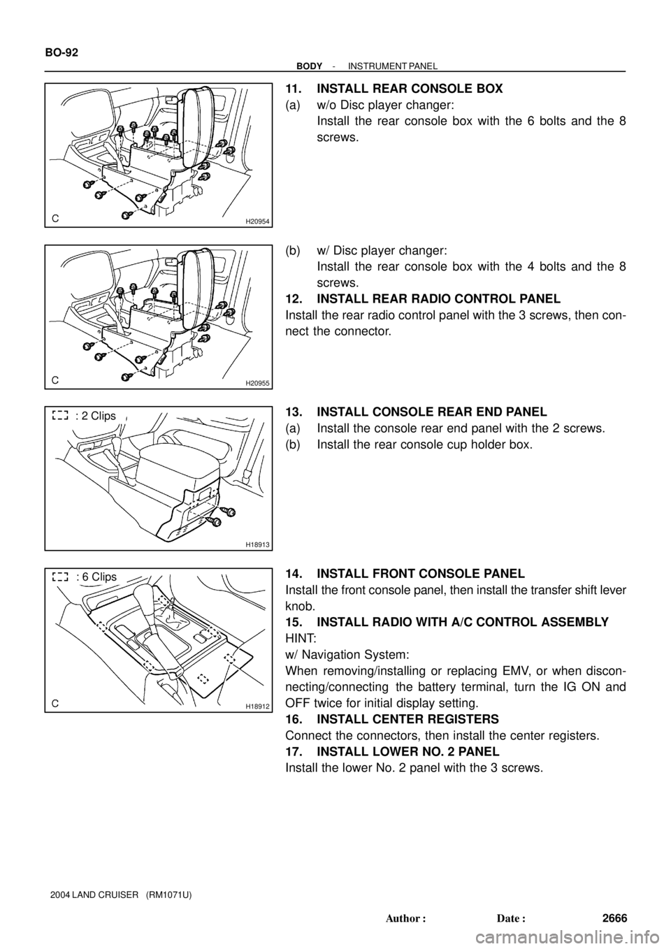
11. INSTALL REAR CONSOLE BOX
(a) w/o Disc player changer:
Install the rear console box with the 6 bolts and the 8
screws.
(b) w/ Disc player changer:
Install the rear console box with the 4 bolts and the 8
screws.
12. INSTALL REAR RADIO CONTROL PANEL
Install the rear radio control panel with the 3 screws, then con-
nect the connector.
13. INSTALL CONSOLE REAR END PANEL
(a) Install the console rear end panel with the 2 screws.
(b) Install the rear console cup holder box.
14. INSTALL FRONT CONSOLE PANEL
Install the front console panel, then install the transfer shift lever
knob.
15. INSTALL RADIO WITH A/C CONTROL ASSEMBLY
HINT:
w/ Navigation System:
When removing/installing or replacing EMV, or when discon-
necting/connecting the battery terminal, turn the IG ON and
OFF twice for initial display setting.
16. INSTALL CENTER REGISTERS
Connect the connectors, then install the center registers.
17. INSTALL LOWER NO. 2 PANEL
Install the lower No. 2 panel with the 3 screws.
Page 425 of 3115

H18912
: 6 Clips
H18913
: 2 Clips
H20954
H20955
H21406
: 5 Clips
- BODYINSTRUMENT PANEL
BO-87
2661 Author�: Date�:
2004 LAND CRUISER (RM1071U)
23. REMOVE FRONT CONSOLE PANEL
(a) Remove the transfer shift lever knob.
(b) Using a screwdriver, remove the front console panel.
HINT:
Tape up the screwdriver tip before use.
24. REMOVE CONSOLE REAR END PANEL
(a) Remove the rear console cup holder box.
(b) Remove the 2 screws.
(c) Using a screwdriver, remove the console rear end panel.
HINT:
Tape up the screwdriver tip before use.
25. REMOVE REAR RADIO CONTROL PANEL
Disconnect the connector, then remove the 3 screws and the
rear radio control panel.
26. REMOVE REAR CONSOLE BOX
(a) w/o Disc player changer :
Remove the 6 bolts, the 8 screws and the rear console
box.
(b) w/ Disc player changer :
Remove the 4 bolts, the 8 screws and the rear console
box.
27. REMOVE CENTER LOWER CLUSTER FINISH PANEL
Using a screwdriver, remove the center lower cluster finish pan-
el, then disconnect the connector.
HINT:
Tape up the screwdriver tip before use.