Page 521 of 3115

F02821
Hydraulic Brake
BoosterSub-wire Harness S (SST)
AIR BLEED
FRONT
REAR BR-6
- BRAKEBRAKE FLUID
2142 Author�: Date�:
2004 LAND CRUISER (RM1071U)
(b) Connect the actuator checker (SST) to the hydraulic
brake booster side wire harness via the sub-wire harness
(SST), as shown in the chart below.
SST 09990-00150, 09990-00480
HINT:
Connect the connector with the label of ºAIR BLEEDº attached
to the connector of actuator checker.
(c) Connect the red cable of the checker to the battery posi-
tive (+) terminal and the black cable to the negative (-) ter-
minal.
(d) Turn the ignition switch OFF, depress the brake pedal
more than 40 times.
HINT:
When a pressure in power supply system is released, reaction
force becomes light and stroke becomes longer.
(e) Turn the ignition switch ON, check that the pump stops af-
ter 30 to 40 sec.
NOTICE:
When the pump does not stop, repeat step (d) and (e) again.
(f) With the ignition switch remained ON, depress the brake
pedal more than 20 times.
(g) Observe the procedure in step 4 and bleed the right and
left front wheel caliper.
(h) Holding the brake pedal depressed, bleed the right and
left rear brake caliper.
HINT:
It is not necessary to depress the pedal continuously, as brake
fluid flows out by first depressing.
Page 523 of 3115

F04458
BR-8
- BRAKEBRAKE FLUID
2144 Author�: Date�:
2004 LAND CRUISER (RM1071U)
(l) Observe the procedure in step (k) and bleed left rear
brake line.
(m) Disconnect the actuator checker (SST) and sub-wire har-
ness (SST) from the actuator.
SST 09990-00150, 09990-00480
(n) Connect the 2 connectors to the hydraulic brake booster.
(o) Clear the DTC (See page DI-505).
4. BLEED BRAKE LINE
(a) Connect the vinyl tube to the brake caliper.
(b) Depress the brake pedal several times, then loosen the
bleeder plug with the pedal held down.
(c) At the point when fluid stops coming out, tighten the
bleeder plug, then release the brake pedal.
(d) Repeat (b) and (c) until all the air in the fluid has been bled
out.
(e) Repeat the above procedure to bleed the brake line for
each wheel.
Torque: 11 N´m (110 kgf´cm, 8 ft´lbf)
5. CHECK FLUID LEVEL IN RESERVOIR
(a) With the ignition switch OFF, depress the brake pedal
more than 40 times.
HINT:
When a pressure in power supply system is released, reaction
force becomes light and stroke becomes longer.
(b) Remove the reservoir cap. Add brake fluid up to the
ºMAXº line.
Fluid: SAE J1703 or FMVSS NO. 116 DOT3
Page 526 of 3115

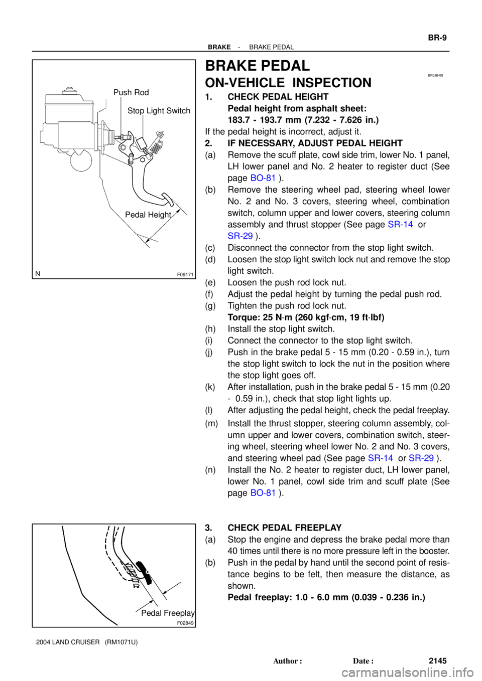
F09171
Stop Light Switch Push Rod
Pedal Height
BR0JB-08
F02849
Pedal Freeplay
- BRAKEBRAKE PEDAL
BR-9
2145 Author�: Date�:
2004 LAND CRUISER (RM1071U)
BRAKE PEDAL
ON-VEHICLE INSPECTION
1. CHECK PEDAL HEIGHT
Pedal height from asphalt sheet:
183.7 - 193.7 mm (7.232 - 7.626 in.)
If the pedal height is incorrect, adjust it.
2. IF NECESSARY, ADJUST PEDAL HEIGHT
(a) Remove the scuff plate, cowl side trim, lower No. 1 panel,
LH lower panel and No. 2 heater to register duct (See
page BO-81).
(b) Remove the steering wheel pad, steering wheel lower
No. 2 and No. 3 covers, steering wheel, combination
switch, column upper and lower covers, steering column
assembly and thrust stopper (See page SR-14 or
SR-29).
(c) Disconnect the connector from the stop light switch.
(d) Loosen the stop light switch lock nut and remove the stop
light switch.
(e) Loosen the push rod lock nut.
(f) Adjust the pedal height by turning the pedal push rod.
(g) Tighten the push rod lock nut.
Torque: 25 N´m (260 kgf´cm, 19 ft´lbf)
(h) Install the stop light switch.
(i) Connect the connector to the stop light switch.
(j) Push in the brake pedal 5 - 15 mm (0.20 - 0.59 in.), turn
the stop light switch to lock the nut in the position where
the stop light goes off.
(k) After installation, push in the brake pedal 5 - 15 mm (0.20
- 0.59 in.), check that stop light lights up.
(l) After adjusting the pedal height, check the pedal freeplay.
(m) Install the thrust stopper, steering column assembly, col-
umn upper and lower covers, combination switch, steer-
ing wheel, steering wheel lower No. 2 and No. 3 covers,
and steering wheel pad (See page SR-14 or SR-29).
(n) Install the No. 2 heater to register duct, LH lower panel,
lower No. 1 panel, cowl side trim and scuff plate (See
page BO-81).
3. CHECK PEDAL FREEPLAY
(a) Stop the engine and depress the brake pedal more than
40 times until there is no more pressure left in the booster.
(b) Push in the pedal by hand until the second point of resis-
tance begins to be felt, then measure the distance, as
shown.
Pedal freeplay: 1.0 - 6.0 mm (0.039 - 0.236 in.)
Page 535 of 3115
BR0TA-04
F04974
F04975
- BRAKEFRONT BRAKE CALIPER
BR-19
2155 Author�: Date�:
2004 LAND CRUISER (RM1071U)
REMOVAL
1. REMOVE FRONT WHEEL
Torque: 103 N´m (1,050 kgf´cm, 76 ft´lbf)
2. DISCONNECT BRAKE LINE
(a) Remove the union bolt and 2 gaskets from the caliper,
then disconnect the flexible hose from the caliper.
Torque: 30 N´m (310 kgf´cm, 22 ft´lbf)
(b) Use a container to catch the brake fluid as it drains out.
3. REMOVE CALIPER
Remove the 2 mounting bolts and remove the caliper.
Torque: 123 N´m (1,250 kgf´cm, 90 ft´lbf)
4. REMOVE CLIP AND 2 PINS
5. REMOVE 2 PAD RETAINER CLIPS
6. REMOVE 2 PADS, ANTI-SQUEAL SHIMS AND PAD
RETAINERS
Page 537 of 3115

BR0JI-1 1
F04993
F04994
F04995
BR-16
- BRAKEFRONT BRAKE PAD
2152 Author�: Date�:
2004 LAND CRUISER (RM1071U)
REPLACEMENT
1. REMOVE FRONT WHEEL
2. INSPECT PAD LINING THICKNESS
Check the pad thickness through the caliper inspection hole
and replace the pads if they are not within the specification.
Minimum thickness: 1.0 mm (0.039 in.)
3. REMOVE CLIP AND 2 PINS
4. REMOVE 2 PAD RETAINER CLIPS
5. REMOVE 2 PADS, ANTI-SQUEAL SHIMS AND PAD
RETAINERS
NOTICE:
The pad retainer clip and clip can be used again provided
that they have sufficient rebound, no deformation, cracks
or wear, and have had all rust, dirt and foreign particles
cleaned off.
6. CHECK DISC THICKNESS AND DISC RUNOUT
(See page BR-21)
7. INSTALL NEW PADS
NOTICE:
When replacing worn pads, the anti-squeal shims must be
replaced together with the pad.
(a) Draw out a small amount of brake fluid from the reservoir.
(b) Press in the piston with a hammer handle or an equiva-
lent.
HINT:
�Always change the pads on one wheel at a time as there
is a possibility of opposite piston fling out.
�If the piston is difficult to push in, loosen the bleeder plug
and push in the piston while letting some brake fluid es-
cape.
(c) Install the 2 pad retainers to each caliper piston.
(d) Install the anti-squeal shim to each pad.
HINT:
Apply disc brake grease to both sides of the anti-squeal shims
(See page BR-15).
(e) Install the 2 pads.
HINT:
Apply disc brake grease to the pads indicated by the arrows
(See page BR-15).
Page 538 of 3115
- BRAKEFRONT BRAKE PAD
BR-17
2153 Author�: Date�:
2004 LAND CRUISER (RM1071U)
NOTICE:
There should be no oil or grease adhering to the friction
surfaces of the pads or the disc.
8. INSTALL 2 PAD RETAINER CLIPS AND 2 PINS
9. INSTALL CLIP
10. INSTALL FRONT WHEEL
Torque: 103 N´m (1,050 kgf´cm, 76 ft´lbf)
11. DEPRESS BRAKE PEDAL SEVERAL TIMES
12. CHECK THAT FLUID LEVEL IS AT MAX LINE
Page 552 of 3115

- BRAKEHYDRAULIC BRAKE BOOSTER
BR-43
2179 Author�: Date�:
2004 LAND CRUISER (RM1071U)
(5) When the solenoids are OFF, check that the brake
pedal can be depressed.
If the pedal cannot be depressed, replace the hydraulic brake
booster.
(6) Once, release the brake pedal. After depressing
and holding the brake pedal with stable force, turn
the SFLH and SFLR solenoids ON simultaneously.
HINT:
To protect the solenoids, TOYOTA hand-held tester turns OFF
automatically for 2 sec. after every solenoid has been turned
ON.
(7) Once release the brake pedal when the solenoids
are OFF, check that the brake pedal can be de-
pressed.
If the pedal cannot be depressed, replace the hydraulic brake
booster.
(g) Jack up and support the vehicle.
(h) Release the parking brake lever.
(i) Inspect the rear ABS solenoid.
(1) Select the ºSRHº on the TOYOTA hand-held tester.
(2) Turn the ºSRHº ON with the TOYOTA hand-held
tester and depress the brake pedal with stable
force, and rotate the right rear wheel by hand and
check it.
HINT:
�To protect the solenoids, TOYOTA hand-held tester turns
OFF automatically for 2 sec. after every solenoid has
been turned ON.
�When rotating the wheel fast, the fail-safe function is acti-
vated and judgement cannot be made properly. So rotate
the wheel as slowly as possible.
�When solenoid is OFF, the wheel might stop temporarily.
However if the wheel rotates again, the function works
normally.
If the rear wheels stop, replace the hydraulic brake booster.
(3) Once, release the brake pedal and turn the ºSRHº
OFF, after depressing the brake pedal with stable
force and stop the rear right wheel by hand and
check it.
If the rear wheel rotate, replace the hydraulic brake booster.
(4) Depress the pedal with stable force, then turn the
ºSRHº and ºSRRº ON simultaneously.
(5) When the solenoids are ON, rotate the rear wheel
by hand and check it.
HINT:
�To protect the solenoids, TOYOTA hand-held tester turns
OFF automatically for 2 sec. after every solenoid has
been turned ON.
Page 553 of 3115

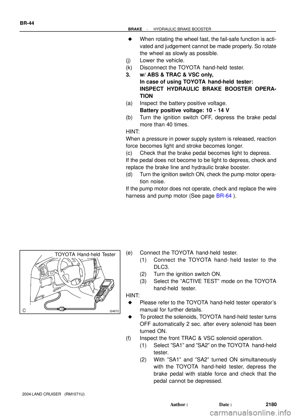
I24672
TOYOTA Hand-held Tester
BR-44
- BRAKEHYDRAULIC BRAKE BOOSTER
2180 Author�: Date�:
2004 LAND CRUISER (RM1071U)
�When rotating the wheel fast, the fail-safe function is acti-
vated and judgement cannot be made properly. So rotate
the wheel as slowly as possible.
(j) Lower the vehicle.
(k) Disconnect the TOYOTA hand-held tester.
3. w/ ABS & TRAC & VSC only,
In case of using TOYOTA hand-held tester:
INSPECT HYDRAULIC BRAKE BOOSTER OPERA-
TION
(a) Inspect the battery positive voltage.
Battery positive voltage: 10 - 14 V
(b) Turn the ignition switch OFF, depress the brake pedal
more than 40 times.
HINT:
When a pressure in power supply system is released, reaction
force becomes light and stroke becomes longer.
(c) Check that the brake pedal becomes light to depress.
If the pedal does not become to be light to depress, check and
replace the brake line and hydraulic brake booster.
(d) Turn the ignition switch ON, check the pump motor opera-
tion noise.
If the pump motor does not operate, check and replace the wire
harness and pump motor (See page BR-64).
(e) Connect the TOYOTA hand-held tester.
(1) Connect the TOYOTA hand- held tester to the
DLC3.
(2) Turn the ignition switch ON.
(3) Select the ºACTIVE TESTº mode on the TOYOTA
hand-held tester.
HINT:
�Please refer to the TOYOTA hand-held tester operator's
manual for further details.
�To protect the solenoids, TOYOTA hand-held tester turns
OFF automatically 2 sec. after every solenoid has been
turned ON.
(f) Inspect the front TRAC & VSC solenoid operation.
(1) Select ºSA1º and ºSA2º on the TOYOTA hand-held
tester.
(2) With ºSA1º and ºSA2º turned ON simultaneously
with the TOYOTA hand-held tester, depress the
brake pedal with stable force and check that the
pedal cannot be depressed.