Page 2438 of 3115

(k) Care must be taken when jacking up and supporting the
vehicle. Be s")
IN0253
WRONG CORRECT
IN0252
WRONG CORRECT IN-6
- INTRODUCTIONREPAIR INSTRUCTIONS
6 Author�: Date�:
2004 LAND CRUISER (RM1071U)
(k) Care must be taken when jacking up and supporting the
vehicle. Be sure to lift and support the vehicle at the prop-
er locations (See page IN-8).
�Cancel the parking brake on the level place and
shift the transmission in N position.
�When jacking up the front wheels of the vehicle at
first place stoppers behind the rear wheels.
�When jacking up the rear wheels of the vehicle at
first place stoppers before the front wheels.
�When either the front or rear wheels only should be
jacked up, set rigid racks and place stoppers in front
and behind the other wheels on the ground.
�After the vehicle is jacked up, be sure to support it
on rigid racks. It is extremely dangerous to do any
work on a vehicle raised on a jack alone, even for
a small job that can be finished quickly.
(l) Observe the following precautions to avoid damage to the
following parts:
(1) Do not open the cover or case of the ECU unless
absolutely necessary. (If the IC terminals are
touched, the IC may be destroyed by static electric-
ity.)
(2) To disconnect vacuum hoses, pull off the end, not
the middle of the hose.
(3) To pull apart electrical connectors, pull on the con-
nector itself, not the wires.
(4) Be careful not to drop electrical components, such
as sensors or relays. If they are dropped on a hard
floor, they should be replaced and not reused.
(5) When steam cleaning an engine, protect the elec-
tronic components, air filter and emission-related
components from water.
(6) Never use an impact wrench to remove or install
temperature switches or temperature sensors.
(7) When checking continuity at the wire connector, in-
sert the tester probe carefully to prevent terminals
from bending.
(8) When using a vacuum gauge, never force the hose
onto a connector that is too large. Use a step-down
adapter for adjustment. Once the hose has been
stretched, it may leak air.
Page 2444 of 3115

(k) Care must be taken when jacking up and supporting the
vehicle. Be s")
IN0253
WRONG CORRECT
IN0252
WRONG CORRECT IN-6
- INTRODUCTIONREPAIR INSTRUCTIONS
6 Author�: Date�:
2004 LAND CRUISER (RM1071U)
(k) Care must be taken when jacking up and supporting the
vehicle. Be sure to lift and support the vehicle at the prop-
er locations (See page IN-8).
�Cancel the parking brake on the level place and
shift the transmission in N position.
�When jacking up the front wheels of the vehicle at
first place stoppers behind the rear wheels.
�When jacking up the rear wheels of the vehicle at
first place stoppers before the front wheels.
�When either the front or rear wheels only should be
jacked up, set rigid racks and place stoppers in front
and behind the other wheels on the ground.
�After the vehicle is jacked up, be sure to support it
on rigid racks. It is extremely dangerous to do any
work on a vehicle raised on a jack alone, even for
a small job that can be finished quickly.
(l) Observe the following precautions to avoid damage to the
following parts:
(1) Do not open the cover or case of the ECU unless
absolutely necessary. (If the IC terminals are
touched, the IC may be destroyed by static electric-
ity.)
(2) To disconnect vacuum hoses, pull off the end, not
the middle of the hose.
(3) To pull apart electrical connectors, pull on the con-
nector itself, not the wires.
(4) Be careful not to drop electrical components, such
as sensors or relays. If they are dropped on a hard
floor, they should be replaced and not reused.
(5) When steam cleaning an engine, protect the elec-
tronic components, air filter and emission-related
components from water.
(6) Never use an impact wrench to remove or install
temperature switches or temperature sensors.
(7) When checking continuity at the wire connector, in-
sert the tester probe carefully to prevent terminals
from bending.
(8) When using a vacuum gauge, never force the hose
onto a connector that is too large. Use a step-down
adapter for adjustment. Once the hose has been
stretched, it may leak air.
Page 2584 of 3115

TORQUE SPECIFICATION
Part tightenedN´mkgf´cmft´lbf
Brake line union nut1515511
Hydraulic brake booster")
SS063-18
- SERVICE SPECIFICATIONSBRAKE
SS-41
181 Author�: Date�:
2004 LAND CRUISER (RM1071U)
TORQUE SPECIFICATION
Part tightenedN´mkgf´cmft´lbf
Brake line union nut1515511
Hydraulic brake booster clevis lock nut2526019
Hydraulic brake booster x Pedal bracket1515511
Brake pedal bracket set bolt2020014
ABS ECU or ABS & BA & TRAC & VSC ECU set nut5.05144 in.´lbf
Bleeder plug1111 08
Front disc brake caliper x Flexible hose3031022
Front disc brake mounting bolt x Steering knuckle1231,25090
Rear disc brake caliper installation bolt2627020
Rear disc brake caliper x Flexible hose3031022
Rear disc brake torque plate x Rear backing plate1031,05076
Reservoir set screw1.717.515.2 in.´lbf
Master cylinder pressure sensor (w/ ABS & BA & TRAC & VSC only)8183060
Accumulator x Booster pump motor5455036
Front speed sensor installation bolt8.08271 in.´lbf
Front speed sensor harness clamp bolt131309
Rear speed sensor installation bolt8.08271 in.´lbf
Rear speed sensor harness clamp bolt131309
Front brake disc x Front axle hub7475054
Parking brake bellcrank assembly x Backing plate131309
Bellcrank stopper bolt lock nut5.45548 in.´lbf
Page 2611 of 3115

TORQUE SPECIFICATION
FRONT
Part tightenedN´mkgf´cmft´lbf
Hub bolt1311,34097
Knuckle stop")
SS0OK-05
SS-38
- SERVICE SPECIFICATIONSSUSPENSION AND AXLE
178 Author�: Date�:
2004 LAND CRUISER (RM1071U)
TORQUE SPECIFICATION
FRONT
Part tightenedN´mkgf´cmft´lbf
Hub bolt1311,34097
Knuckle stopper bolt lock nut4445032
Steering knuckle x Brake caliper1231,25091
Disc x Axle hub7475055
Flange x Axle hub3333524
Axle hub bearing lock nut6465047
Flexible hose x Bracket2829021
ABS speed sensor installation bolt8.08271 in.´lbf
ABS speed sensor wire harness x Steering knuckle arm1313010
ABS speed sensor wire harness bracket x Steering knuckle2829021
Steering knuckle arm x Steering knuckle1471,500108
Tie rod end x Steering knuckle arm1221,25090
Upper suspension arm x Steering knuckle11 01,12581
Lower suspension arm x Steering knuckle1591,62511 7
Oil seal x Steering knuckle1818513
Propeller shaft x Companion flange8082059
Body x No. 3 frame crossmember6869550
No. 3 frame crossmember x Differential support1861,900137
Differential support x Differential tube1861,900137
Differential support x Differential carrier7880058
Differential support x Body1861,900137
Differential carrier cover x Body1861,900137
Breather hose bracket x Carrier cover1717313
Filler plug4950036
Drain plug4950036
Differential tube x Differential carrier1051,07077
Bearing cap x Differential carrier8587063
Oil deflector x Carrier cover7.37465 in.´lbf
Carrier cover x Differential carrier4747535
Differential case x Ring gear9798572
Companion flange x Drive pinionSee page SA-47
Lower suspension arm x Shock absorber1351,400100
Piston rod x Body6870050
Torque arm x Lower suspension arm2252,300166
ABS speed sensor wire harness x Upper suspension arm1313010
Upper suspension arm x Body981,00072
Stabilizer bar link x Lower suspension arm5253038
Lower suspension arm x Body2302,350170
Stabilizer bar x Stabilizer bar link2525018
Stabilizer bar bracket x Body1818513
Page 2898 of 3115

(d) Using a spring tension gauge, check the preload.
Preload (at starting):
42 - 67 N (")
F04362
90°
F04363
- SUSPENSION AND AXLEFRONT AXLE HUB
SA-17
1967 Author�: Date�:
2004 LAND CRUISER (RM1071U)
(d) Using a spring tension gauge, check the preload.
Preload (at starting):
42 - 67 N (4.3 - 6.8 kgf, 9.5 - 15.0 lbf)
HINT:
Make sure to check preload in the direction of rotation.
If the preload is not within the specified value, adjust it again
with the adjusting nut.
(e) Secure the lock nut by bending one of the lock washer
teeth inward and the other lock washer teeth outward.
4. INSTALL FLANGE
(a) Place a new gasket in position on the axle hub.
(b) Install the flange to the axle hub.
(c) Install the 6 cone washers, washers and new nuts.
Torque: 33 N´m (335 kgf´cm, 24 ft´lbf)
(d) Pull out the drive shaft to the outside of the vehicle and
select the snap ring which ensures the clearance be-
tween the tip of the flange and the snap ring is less than
0.2 mm (0.008 in.).
Snap ring thickness:
1.8 mm (0.0709 in.)2.4 mm (0.0945 in.)
2.0 mm (0.0787 in.)2.6 mm (0.1024 in.)
2.2 mm (0.0866 in.)2.8 mm (0.1102 in.)
(e) Using a snap ring expander, install a new snap ring to the
drive shaft.
(f) Install a new grease cap to the flange.
5. INSTALL BRAKE CALIPER
(a) Install the brake caliper, washers and 2 bolts.
Torque: 123 N´m (1,250 kgf´cm, 91 ft´lbf)
(b) Install the flexible hose and bolt to the steering knuckle.
Torque: 28 N´m (290 kgf´cm, 21 ft´lbf)
6. INSTALL FRONT WHEEL
Torque: 131 N´m (1,340 kgf´cm, 97 ft´lbf)
7. CHECK ABS SPEED SENSOR SIGNAL
(See page DI-505)
Page 2901 of 3115

REMOVAL
1. REMOVE FRONT WHEEL
2. REMOVE BRAKE CALIPER
(a) Remove t")
SA144-04
F04367
F04368
F04369
F04370SST SA-12
- SUSPENSION AND AXLEFRONT AXLE HUB
1962 Author�: Date�:
2004 LAND CRUISER (RM1071U)
REMOVAL
1. REMOVE FRONT WHEEL
2. REMOVE BRAKE CALIPER
(a) Remove the bolt and disconnect the flexible hose from
the steering knuckle.
(b) Remove the 2 bolts, washers and brake caliper.
(c) Support the brake caliper securely.
3. REMOVE FLANGE
(a) Using a screwdriver and hammer, remove the grease cap
from the flange.
(b) Using a snap ring expander, remove the snap ring.
(c) Remove the 6 nuts and washers.
(d) Install the 6 nuts temporarily to protect the threads of the
stud bolts.
(e) Using a brass bar and hammer, tap on the bolt heads and
remove the 6 nuts and cone washers.
(f) Remove the flange and gasket.
4. REMOVE AXLE HUB WITH DISC
(a) Using a screwdriver, release the lock washer.
(b) Using SST, remove the lock nut.
SST 09607-60020
(c) Remove the lock washer.
(d) Using SST, remove the adjusting nut.
SST 09607-60020
(e) Remove the axle hub with disc.
NOTICE:
Be careful not to damage the ABS speed sensor rotor and
oil seal.
(f) Remove the claw washer and bearing from the axle hub.
Page 2902 of 3115
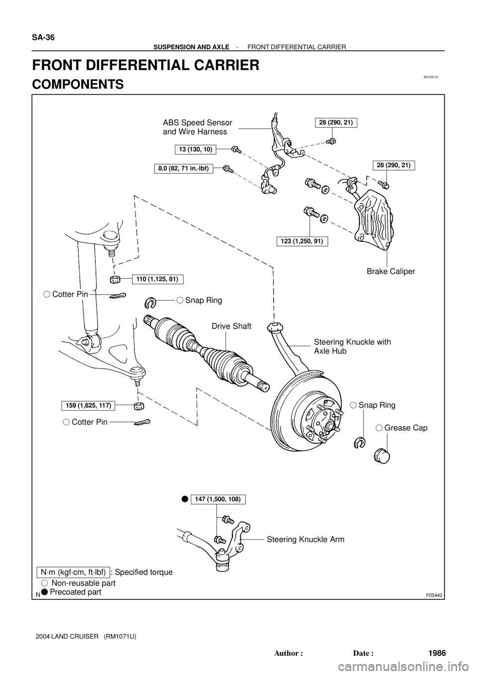
SA1SE-01
F05442
� Grease Cap
Steering Knuckle Arm
� Cotter Pin
Drive Shaft
N´m (kgf´cm, ft´lbf)� Snap Ring Steering Knuckle with
Axle HubBrake Caliper ABS Speed Sensor
and Wire Harness
� Cotter Pin
: Specified torque
� Non-reusable part
� Precoated part
28 (290, 21)
13 (130, 10)
8.0 (82, 71 in.´lbf)
110 (1,125, 81)
159 (1,625, 117)
147 (1,500, 108)
123 (1,250, 91)
28 (290, 21)
� � Snap Ring
SA-36
- SUSPENSION AND AXLEFRONT DIFFERENTIAL CARRIER
1986 Author�: Date�:
2004 LAND CRUISER (RM1071U)
FRONT DIFFERENTIAL CARRIER
COMPONENTS
Page 2926 of 3115
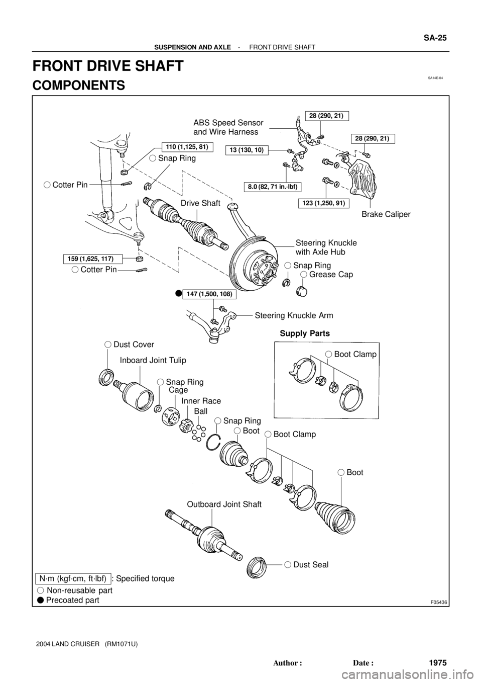
SA14E-04
F05436
110 (1,125, 81)
� Cotter Pin
Drive Shaft
28 (290, 21)
13 (130, 10)
ABS Speed Sensor
and Wire Harness
8.0 (82, 71 in.´lbf)
Brake Caliper
Steering Knuckle
with Axle Hub
� Snap Ring
� Grease Cap
159 (1,625, 117)
� Cotter Pin
� Dust Cover
Inboard Joint Tulip
Cage
Inner Race
Ball
� Boot� Boot Clamp
� Boot
147 (1,500, 108)�
Steering Knuckle Arm
Supply Parts
� Boot Clamp
Outboard Joint Shaft
� Dust Seal
N´m (kgf´cm, ft´lbf) : Specified torque
� Non-reusable part
� Precoated part
28 (290, 21)
123 (1,250, 91)
� Snap Ring � Snap Ring
� Snap Ring
- SUSPENSION AND AXLEFRONT DRIVE SHAFT
SA-25
1975 Author�: Date�:
2004 LAND CRUISER (RM1071U)
FRONT DRIVE SHAFT
COMPONENTS