Page 3054 of 3115
SA149-05
F05160
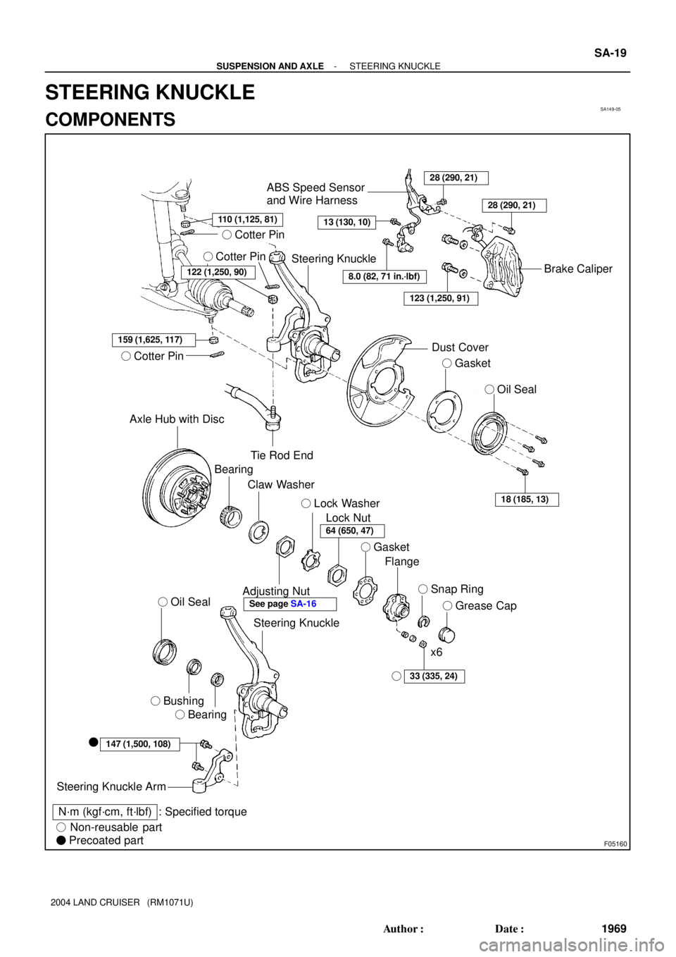
� Cotter Pin
� Cotter Pin
159 (1,625, 117)
� Cotter Pin
Axle Hub with Disc
Tie Rod End
ABS Speed Sensor
and Wire Harness28 (290, 21)
13 (130, 10)
Brake Caliper
Dust Cover
� Gasket
� Oil Seal
18 (185, 13)
Bearing
Claw Washer
Adjusting Nut
Lock Nut � Lock Washer
� Gasket
Flange
� Snap Ring
� Grease Cap
33 (335, 24)
x6
Steering Knuckle
� Oil Seal
� Bushing
� Bearing
147 (1,500, 108)�
Steering Knuckle Arm
N´m (kgf´cm, ft´lbf) : Specified torque
� Non-reusable part
� Precoated part
Steering Knuckle
8.0 (82, 71 in.´lbf)
123 (1,250, 91)
122 (1,250, 90)
28 (290, 21)
�
64 (650, 47)
See page SA-16
110 (1,125, 81)
- SUSPENSION AND AXLESTEERING KNUCKLE
SA-19
1969 Author�: Date�:
2004 LAND CRUISER (RM1071U)
STEERING KNUCKLE
COMPONENTS
Page 3056 of 3115

INSTALLATION
1. INSTALL STEERING KNUCKLE
(a) Apply synthetic oil and lithium")
SA14D-04
F04405
F04372
A
BC SA-24
- SUSPENSION AND AXLESTEERING KNUCKLE
1974 Author�: Date�:
2004 LAND CRUISER (RM1071U)
INSTALLATION
1. INSTALL STEERING KNUCKLE
(a) Apply synthetic oil and lithium soap base chassis grease,
NLGI No. 1 to the drive shaft.
(b) Support the lower suspension arm with jack and connect
the steering knuckle to the lower suspension arm.
NOTICE:
Be careful not to damage the oil seal.
(c) Temporarily install the nut to lower suspension arm.
(d) Raise up the lower suspension arm using a jack and
install the steering knuckle to the upper suspension arm
with a nut.
Torque: 110 N´m (1,125 kgf´cm, 81 ft´lbf)
(e) Install a new cotter pin.
If the holes for the cotter pin are not aligned, tighten the nut fur-
ther up to 60°.
(f) Torque the nut of the lower suspension arm.
Torque: 159 N´m (1,625 kgf´cm, 117 ft´lbf)
(g) Install a new cotter pin.
2. CONNECT TIE ROD END
(a) Connect the tie rod end to steering knuckle with nut.
Torque: 122 N´m (1,250 kgf´cm, 91 ft´lbf)
(b) Install a new cotter pin.
If the holes for the cotter pin are not aligned, tighten the nut fur-
ther up to 60°.
3. CONNECT ABS SPEED SENSOR AND WIRE HAR-
NESS
Install the wire harness and 3 bolts.
Torque:
A: 8.0 N´m (82 kgf´cm, 71 in.´lbf)
B: 13 N´m (130 kgf´cm, 10 ft´lbf)
C: 28 N´m (290 kgf´cm, 21 ft´lbf)
4. INSTALL DUST COVER, GASKET AND OIL SEAL
Install the dust cover, new gasket and oil seal with the 4 bolts.
Torque: 18 N´m (185 kgf´cm, 13 ft´lbf)
5. INSTALL FRONT AXLE HUB (See page SA-16)
Page 3058 of 3115
SA14A-04
F04371
F04372
F04373
SST
F04374
SST
SA-20
- SUSPENSION AND AXLESTEERING KNUCKLE
1970 Author�: Date�:
2004 LAND CRUISER (RM1071U)
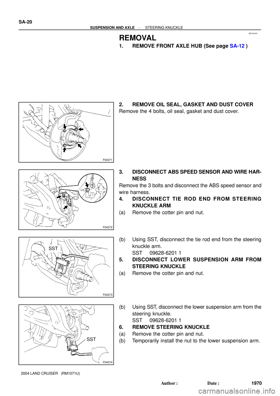
REMOVAL
1. REMOVE FRONT AXLE HUB (See page SA-12)
2. REMOVE OIL SEAL, GASKET AND DUST COVER
Remove the 4 bolts, oil seal, gasket and dust cover.
3. DISCONNECT ABS SPEED SENSOR AND WIRE HAR-
NESS
Remove the 3 bolts and disconnect the ABS speed sensor and
wire harness.
4. DISCONNECT TIE ROD END FROM STEERING
KNUCKLE ARM
(a) Remove the cotter pin and nut.
(b) Using SST, disconnect the tie rod end from the steering
knuckle arm.
SST 09628-6201 1
5. DISCONNECT LOWER SUSPENSION ARM FROM
STEERING KNUCKLE
(a) Remove the cotter pin and nut.
(b) Using SST, disconnect the lower suspension arm from the
steering knuckle.
SST 09628-6201 1
6. REMOVE STEERING KNUCKLE
(a) Remove the cotter pin and nut.
(b) Temporarily install the nut to the lower suspension arm.
Page 3063 of 3115
 Noise in rear axle
1. Oil level (Low or wrong grade)
2. Excessive backlash between pinion and ring gear
3.")
SA-2
- SUSPENSION AND AXLETROUBLESHOOTING
1952 Author�: Date�:
2004 LAND CRUISER (RM1071U) Noise in rear axle
1. Oil level (Low or wrong grade)
2. Excessive backlash between pinion and ring gear
3. Ring, pinion or side gears (Worn or chipped)
4. Pinion shaft bearing (Worn)
5. Axle shaft bearing (Worn)SA-95
SA-102
SA-121
SA-143
SA-102
SA-121
SA-143
SA-102
SA-121
SA-143
SA-83
Oil leak from rear axle1. Oil seal (Worn or damaged)
2. Rear axle housing (Cracked)SA-83
-
Oil leak from rear differential
1. Oil level (Too high or wrong grade)
2. Rear differential front oil seal (Worn or damaged)
3. Companion flange (Loosen or damaged)SA-95
SA-95
SA-102
SA-121
SA-143
Diff. lock Indicator lights do not light up
1. Fusible link (Blown)
2. GAUGE fuse (Blown)
3. Bulb (Burned out)
4. Wiring or ground (Faulty)-
-
-
-
Diff. lock Indicator lights do not light up
(Diff. lock control switch RR position)
1. Diff. fuse (Blown)
2. Diff. lock control switch (Faulty)
3. Diff. lock ECU (Faulty)
4. Wiring or ground (Faulty)-
SA-163
SA-163
-
Differential lock does not operate
1. Diff. lock control switch (Faulty)
2. Diff. lock actuator (Faulty)
3. Diff. lock ECU (Faulty)
4. Differential carrier (Faulty)
5. Wiring or ground (Faulty)SA-163
SA-163
SA-163
-
-
After differential lock, lock is not released
When vehicle speed is at 8 km/h (5 mph) or more1. Speed sensor (Faulty)
2. Diff. lock ECU (Faulty)
3. Wiring or ground (Faulty)SA-163
SA-163
-
Page 3090 of 3115
TR06P-02
D04346
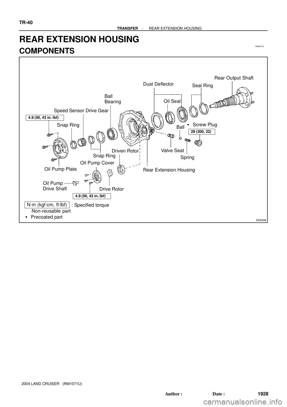
Ball
Bearing� Dust Deflector
Seal RingRear Output Shaft
� Screw Plug
Ball
Rear Extension Housing Driven Rotor Speed Sensor Drive Gear
Drive Rotor Oil Pump CoverSpring Valve Seat
4.9 (50, 43 in.´lbf)
29 (300, 22)
� Oil Seal
� Snap Ring Snap Ring
Oil Pump
Drive ShaftOil Pump Plate
N´m (kgf´cm, ft´lbf)
: Specified torque
� Non-reusable part
� Precoated part
4.9 (50, 43 in.´lbf)
TR-40
- TRANSFERREAR EXTENSION HOUSING
1928 Author�: Date�:
2004 LAND CRUISER (RM1071U)
REAR EXTENSION HOUSING
COMPONENTS
Page 3092 of 3115

6. REMOVE OIL PUMP PLATE
Remove the 3 bolts and oil pump plate.
7. REMOVE")
D04353
TF0959
SST
Q08385
Q08481
SST TR-42
- TRANSFERREAR EXTENSION HOUSING
1930 Author�: Date�:
2004 LAND CRUISER (RM1071U)
6. REMOVE OIL PUMP PLATE
Remove the 3 bolts and oil pump plate.
7. REMOVE SPEED SENSOR DRIVE GEAR
(a) Using a snap ring expander, remove the snap ring.
(b) Remove the speed sensor drive gear.
8. REMOVE REAR OUTPUT SHAFT
(a) Using a snap ring expander, remove the snap ring.
(b) Using SST and a hammer, remove the rear output shaft.
SST 09325-12010
(c) Remove the 2 seal rings from the rear output shaft.
9. REMOVE DUST DEFLECTOR
(a) Using a screwdriver and hammer, remove the rear exten-
sion housing dust deflector.
(b) Using a screwdriver and hammer, remove the rear output
shaft dust deflector.
10. REMOVE OIL SEAL
Using a screwdriver, pry out the oil seal from the rear extension
housing.
11. REMOVE BALL BEARING
(a) Using a screwdriver, remove the snap ring.
(b) Using SST and a press, remove the ball bearing from the
rear extension housing.
SST 09316-6001 1 (09316-00011, 09316-00021)
Page 3095 of 3115
TF0969
SST
TF0958
D04353
- TRANSFERREAR EXTENSION HOUSING
TR-45
1933 Author�: Date�:
2004 LAND CRUISER (RM1071U)
4. INSTALL REAR OUTPUT SHAFT
(a) Using SST and a press, install the rear output shaft.
SST 09316- 20011, 09316- 60011 (09316- 00011,
09316-00031)
(b) Install the 2 seal rings to the rear output shaft.
(c) Select a snap ring that will allow the minimum axial play.
MarkThickness mm (in.)
11.95 (0.0768)
22.05 (0.0807)
32.15 (0.0847)
42.25 (0.0886)
(d) Using a snap ring expander, install a new snap ring.
5. INSTALL SPEED SENSOR DRIVE GEAR
(a) Install the speed sensor drive gear.
(b) Using a snap ring expander, install the snap ring.
6. INSTALL OIL PUMP PLATE
(a) Install the oil pump plate.
(b) Install and torque the 3 bolts.
Torque: 4.9 N´m (50 kgf´cm, 43 in.´lbf)
Page 3097 of 3115

Transfer Indicator Switch
(Low Switch)
37 (380, 27)")
TR069-02
D02653
� Gasket
Rear Extension
Housing
Vehicle Speed Sensor
Driven Gear
Oil Strainer
Case Cover Transfer Indicator Switch
(Neutral Switch)
Transfer Indicator Switch
(Low Switch)
37 (380, 27)
37 (380, 27)
37 (380, 27)
x9
�
37 (380, 27)
�37 (380, 27)
x5 Adjusting Shim
Rear Case
Snap Ring Center Differential
Assemblyx8
Bearing Race
Shift Fork No. 1
Idler Gear Assembly Bearing Race
Shift Fork No. 1 Shaft
Bearing Race
Bearing Race
Input Shaft Assembly
Lever Lock Pin
Washer
� Oil Seal
Shift Inner Lever
Oil Receiver Motor ActuatorShift Outer Lever
11 (115, 8)
4.9 (50, 43 in.´lbf)
�19 (190, 14)18 (185, 13)
12 (120, 9)
12 (120, 9)
37 (380, 27)
37 (380, 27)
x6 Transfer Indicator Switch
(Center Diff. Lock) Shift Fork No. 2 Shift Fork No. 2 ShaftOutput Gear
Snap Ring
Front Case
Breather Hose
Clutch Sleeve
Front Extension Housing� Oil Seal
N´m (kgf´cm, ft´lbf)
: Specified torque
� Non-reusable part
� Precoated partSpring
Ball Screw Plug
� Gasket
Slotted Spring Pin
Washer
- TRANSFERTRANSFER ASSEMBLY
TR-7
1895 Author�: Date�:
2004 LAND CRUISER (RM1071U)
TRANSFER ASSEMBLY
COMPONENTS