Page 2926 of 3115
SA14E-04
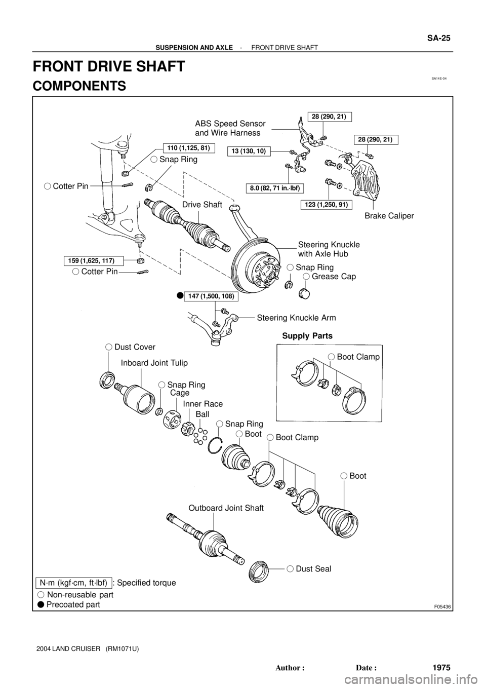
F05436
110 (1,125, 81)
� Cotter Pin
Drive Shaft
28 (290, 21)
13 (130, 10)
ABS Speed Sensor
and Wire Harness
8.0 (82, 71 in.´lbf)
Brake Caliper
Steering Knuckle
with Axle Hub
� Snap Ring
� Grease Cap
159 (1,625, 117)
� Cotter Pin
� Dust Cover
Inboard Joint Tulip
Cage
Inner Race
Ball
� Boot� Boot Clamp
� Boot
147 (1,500, 108)�
Steering Knuckle Arm
Supply Parts
� Boot Clamp
Outboard Joint Shaft
� Dust Seal
N´m (kgf´cm, ft´lbf) : Specified torque
� Non-reusable part
� Precoated part
28 (290, 21)
123 (1,250, 91)
� Snap Ring � Snap Ring
� Snap Ring
- SUSPENSION AND AXLEFRONT DRIVE SHAFT
SA-25
1975 Author�: Date�:
2004 LAND CRUISER (RM1071U)
FRONT DRIVE SHAFT
COMPONENTS
Page 2929 of 3115
SA14I-08
- SUSPENSION AND AXLEFRONT DRIVE SHAFT
SA-33
1983 Author�: Date�:
2004 LAND CRUISER (RM1071U)
INSTALLATION
Installation is in the reverse order of removal (See page SA-26).
HINT:
After installation, check the ABS speed sensor signal (See page DI-505).
Page 2932 of 3115

REMOVAL
1. REMOVE FRONT WHEEL
Torque: 131 N´m (1,340 kgf´cm")
SA14F-04
F04367
F04368
F05795
A
B
C
F05161
SA-26
- SUSPENSION AND AXLEFRONT DRIVE SHAFT
1976 Author�: Date�:
2004 LAND CRUISER (RM1071U)
REMOVAL
1. REMOVE FRONT WHEEL
Torque: 131 N´m (1,340 kgf´cm, 97 ft´lbf)
2. REMOVE BRAKE CALIPER
(a) Remove the bolt and disconnect the flexible hose from
the steering knuckle.
Torque: 28 N´m (290 kgf´cm, 21 ft´lbf)
(b) Remove the 2 bolts, washers and brake caliper.
Torque: 123 N´m (1,250 kgf´cm, 91 ft´lbf)
(c) Support the brake caliper securely.
3. REMOVE SNAP RING
(a) Using a screwdriver and hammer, remove the grease cap
from the flange.
(b) Using snap ring pliers, remove the snap ring.
4. DISCONNECT ABS SPEED SENSOR AND WIRE HAR-
NESS
Remove the 3 bolts and disconnect the ABS speed sensor and
wire harness.
Torque:
A: 8.0 N´m (82 kgf´cm, 71 in.´lbf)
B: 13 N´m (130 kgf´cm, 10 ft´lbf)
C: 28 N´m (290 kgf´cm, 21 ft´lbf)
5. DISCONNECT STEERING KNUCKLE ARM
Remove the 2 bolts and disconnect the steering knuckle arm.
Torque: 147 N´m (1,500 kgf´cm, 108 ft´lbf)
HINT:
At the time of installation, please refer to the following items.
�Clean the threads of the 2 bolts and steering knuckle with
toluene or trichloroethylene.
Page 2935 of 3115
SA14J-04
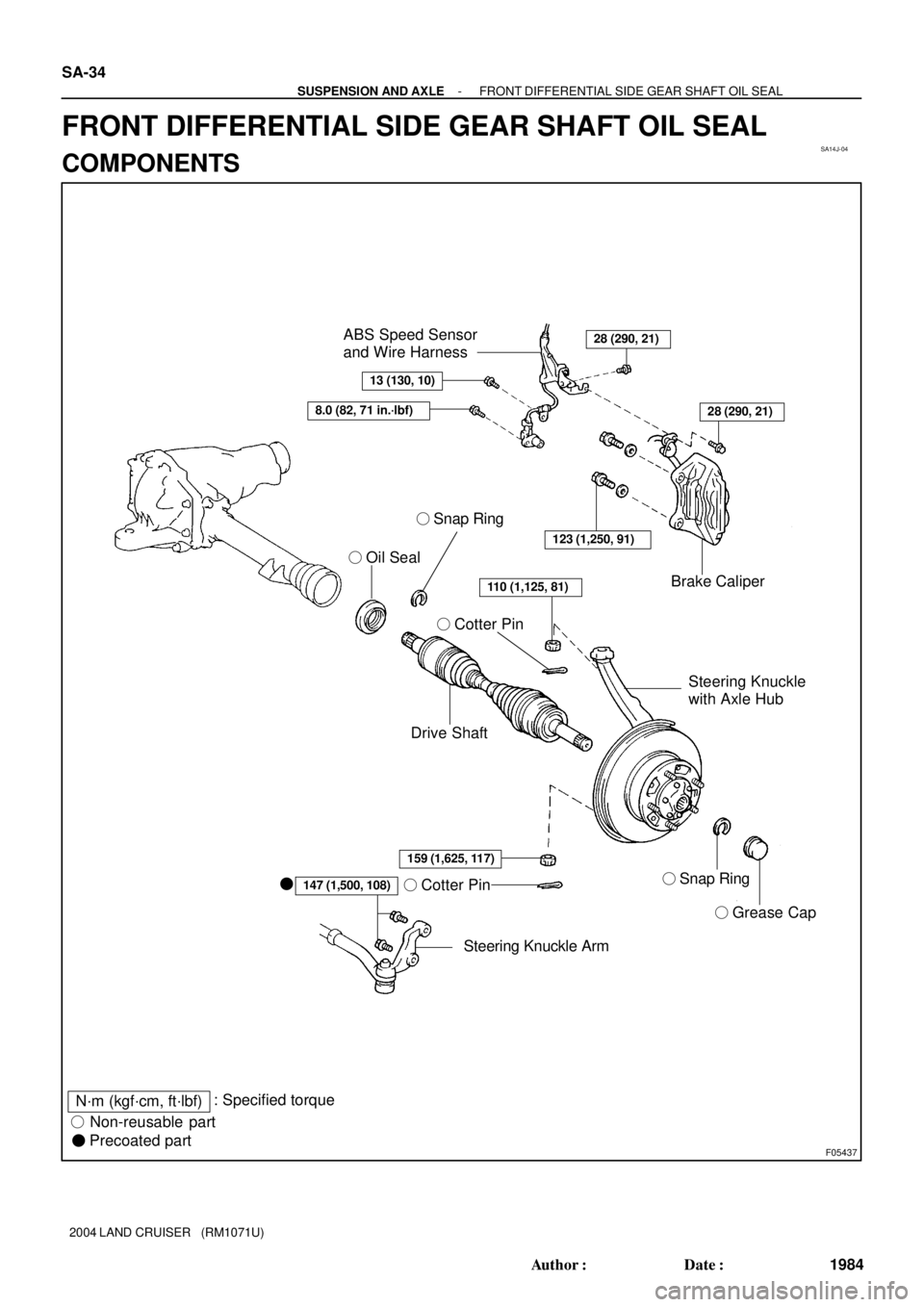
F05437
� Oil Seal
Drive Shaft� Cotter PinBrake Caliper
Steering Knuckle
with Axle Hub
� Snap Ring
� Cotter Pin
� Grease Cap
Steering Knuckle Arm �
147 (1,500, 108)
123 (1,250, 91)
28 (290, 21)
8.0 (82, 71 in.´lbf)
13 (130, 10)
ABS Speed Sensor
and Wire Harness
28 (290, 21)
159 (1,625, 117)
110 (1,125, 81)
� Snap Ring
N´m (kgf´cm, ft´lbf): Specified torque
� Non-reusable part
� Precoated part SA-34
- SUSPENSION AND AXLEFRONT DIFFERENTIAL SIDE GEAR SHAFT OIL SEAL
1984 Author�: Date�:
2004 LAND CRUISER (RM1071U)
FRONT DIFFERENTIAL SIDE GEAR SHAFT OIL SEAL
COMPONENTS
Page 2955 of 3115
SA14Z-02
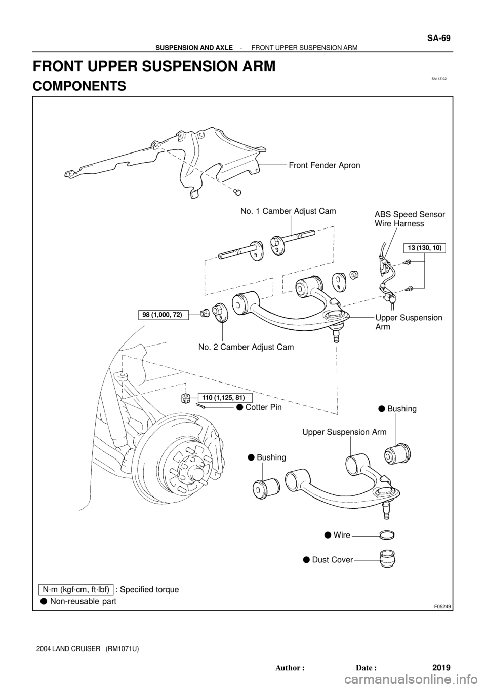
F05249
Front Fender Apron
No. 1 Camber Adjust Cam
ABS Speed Sensor
Wire Harness
No. 2 Camber Adjust CamUpper Suspension
Arm
� Cotter Pin
� Bushing� Bushing
Upper Suspension Arm
� Wire
� Dust Cover
13 (130, 10)
98 (1,000, 72)
110 (1,125, 81)
� Non-reusable part
N´m (kgf´cm, ft´lbf) : Specified torque
- SUSPENSION AND AXLEFRONT UPPER SUSPENSION ARM
SA-69
2019 Author�: Date�:
2004 LAND CRUISER (RM1071U)
FRONT UPPER SUSPENSION ARM
COMPONENTS
Page 2958 of 3115

REMOVAL
1. REMOVE FRONT WHEEL
Torque: 131 N´m (1,")
SA150-02
F04377
F04378
SST
F04379
Matchmarks
SA-70
- SUSPENSION AND AXLEFRONT UPPER SUSPENSION ARM
2020 Author�: Date�:
2004 LAND CRUISER (RM1071U)
REMOVAL
1. REMOVE FRONT WHEEL
Torque: 131 N´m (1,340 kgf´cm, 97 ft´lbf)
2. REMOVE FRONT FENDER APRON
3. DISCONNECT ABS SPEED SENSOR WIRE HARNESS
Remove the 2 bolts and disconnect the ABS speed sensor wire
harness.
Torque: 13 N´m (130 kgf´cm, 10 ft´lbf)
4. DISCONNECT STEERING KNUCKLE FROM UPPER
SUSPENSION ARM
(a) Support the lower suspension arm with a jack.
(b) Remove the cotter pin and nut.
Torque: 110 N´m (1,125 kgf´cm, 81 ft´lbf)
HINT:
At the time of installation, if the holes for the cotter pin are not
aligned, tighten the nut further up to 60°.
(c) Using SST, disconnect the steering knuckle from the up-
per suspension arm.
SST 09628-6201 1
5. REMOVE UPPER SUSPENSION ARM
(a) Place matchmarks on the front and rear No. 2 adjust cams
and body.
(b) Remove the 2 nuts, No. 1 and No. 2 camber adjust cams
and upper suspension arm.
Torque: 98 N´m (1,000 kgf´cm, 72 ft´lbf)
HINT:
At the time of installation, after stabilizing the suspension,
torque the nuts.
Page 2963 of 3115

(d) Torque the front and/or rear adjusting cam nuts.
Torque: 98 N´m (1,000")
SA3213
AB
CD
Front
F05208
- SUSPENSION AND AXLEFRONT WHEEL ALIGNMENT
SA-9
1959 Author�: Date�:
2004 LAND CRUISER (RM1071U)
(d) Torque the front and/or rear adjusting cam nuts.
Torque: 98 N´m (1,000 kgf´cm, 72 ft´lbf)
5. INSPECT TOE-IN
Toe-in:
Toe-in
(total)A + B: 0°06' ± 12' (0.1° ± 0.2°)
C - D: 1 ± 2 mm (0.04 ± 0.08 in.)
If the toe-in is not within the specified value, adjust it at the rack
ends.
6. ADJUST TOE-IN
(a) Check or adjust the lengths of the rack ends, then adjust
the toe-in.
Rack end length difference: 3.0 mm (0.118 in.) or less
(b) Remove the boot clamps.
(c) Loosen the tie rod end lock nuts.
(d) Turn the right and left rack ends by an equal amount to
adjust the toe-in.
HINT:
Try to adjust the toe-in to the center of the specified value.
(e) Tighten the tie rod end lock nuts.
Torque: 55 N´m (560 kgf´cm, 41 ft´lbf)
(f) Place the boots on the seats and install the clamps.
HINT:
Make sure that the boots are not twisted.
(g) Perform the zero point calibration of yaw rate and decel-
eration sensor (See page DI-505).
Page 2966 of 3115
SA15C-02
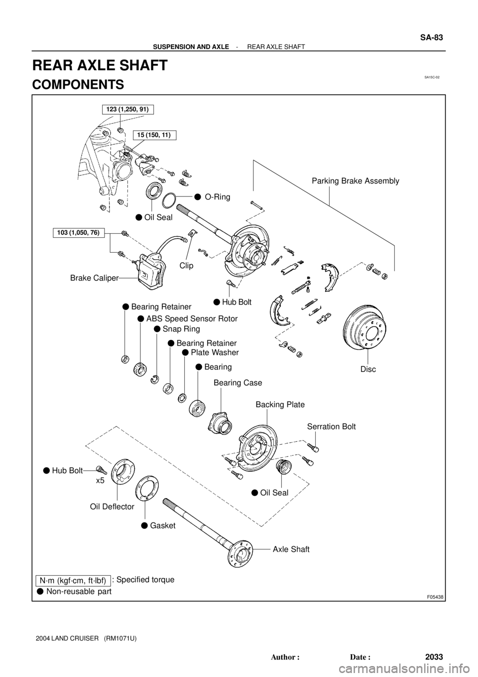
F05438
123 (1,250, 91)
� Oil Seal
� O-Ring
Parking Brake Assembly
Disc
103 (1,050, 76)
Brake Caliper
� Bearing Retainer
� ABS Speed Sensor Rotor
� Snap Ring
Bearing Case
Backing Plate
Serration Bolt
� Oil Seal
� Hub Bolt
Oil Deflector
� Gasket
Axle Shaft
N´m (kgf´cm, ft´lbf): Specified torque
� Non-reusable partx5
15 (150, 11)
� Hub Bolt
Clip
� Bearing Retainer
� Plate Washer
� Bearing
- SUSPENSION AND AXLEREAR AXLE SHAFT
SA-83
2033 Author�: Date�:
2004 LAND CRUISER (RM1071U)
REAR AXLE SHAFT
COMPONENTS