Page 2893 of 3115
SA-166
- SUSPENSION AND AXLEDIFFERENTIAL LOCKING SYSTEM
2116 Author�: Date�:
2004 LAND CRUISER (RM1071U)
(d) Inspect the L position switch (See page TR-49).
(e) Inspect the vehicle speed sensor (See page BE-63).
Page 2896 of 3115
SA145-04
F04408
F04339
F04340
Matchmarks
- SUSPENSION AND AXLEFRONT AXLE HUB
SA-13
1963 Author�: Date�:
2004 LAND CRUISER (RM1071U)
DISASSEMBLY
1. REMOVE OIL SEAL AND BEARING
(a) Using a screwdriver, pry out the oil seal.
(b) Remove the bearing from the axle hub.
2. REMOVE BEARING OUTER RACES
(a) Using a brass bar and hammer, remove the outside bear-
ing outer race.
NOTICE:
Be careful not to damage the ABS speed sensor rotor.
(b) Using a brass bar and hammer, remove the inside bearing
outer race.
3. INSPECT BEARINGS
Clean the bearings and outer races and inspect them for wear
or damage.
4. REMOVE DISC
(a) Mount the axle hub with the disc in a soft jaw vice.
NOTICE:
Close vice until it holds disc, do not tighten further.
(b) Place matchmarks on the axle hub and disc.
(c) Remove the 5 bolts and separate the axle hub and disc.
Page 2897 of 3115

INSTALLATION
1. INSTALL AXLE HUB TO STEERING KNUCKLE
(a) Place")
SA147-09
F04370
SST
F04362
90°
F04370
SST
SA-16
- SUSPENSION AND AXLEFRONT AXLE HUB
1966 Author�: Date�:
2004 LAND CRUISER (RM1071U)
INSTALLATION
1. INSTALL AXLE HUB TO STEERING KNUCKLE
(a) Place the axle hub with disc to the steering knuckle.
NOTICE:
Be careful not to damage the ABS speed sensor rotor and
oil seal.
(b) Install the outer bearing.
(c) Install the claw washer.
2. ADJUST PRELOAD
(a) Install the adjusting nut and using SST, tighten it.
SST 09607-60020
Torque: 59 N´m (600 kgf´cm, 43 ft´lbf)
(b) Turn the axle hub several times to settle down the bear-
ing.
(c) Using SST, loosen the adjusting nut until it can rotate by
hand.
SST 09607-60020
(d) Using SST, retighten the adjusting nut.
SST 09607-60020
Torque: 4.3 - 6.5 N´m (44 - 66 kgf´cm, 38 - 57 in.´lbf)
HINT:
Check that there is no looseness on the bearing.
(e) Using a spring tension gauge, measure the preload.
Preload (at starting):
42 - 67 N (4.3 - 6.8 kgf, 9.5 - 15.0 lbf)
3. INSTALL LOCK WASHER AND LOCK NUT
(a) Install a new lock washer and the lock nut.
(b) Using SST, torque the lock nut.
SST 09607-60020
Torque: 64 N´m (650 kgf´cm, 47 ft´lbf)
(c) Check that the axle hub rotates smoothly and there is no
looseness on the bearing.
Page 2898 of 3115

(d) Using a spring tension gauge, check the preload.
Preload (at starting):
42 - 67 N (")
F04362
90°
F04363
- SUSPENSION AND AXLEFRONT AXLE HUB
SA-17
1967 Author�: Date�:
2004 LAND CRUISER (RM1071U)
(d) Using a spring tension gauge, check the preload.
Preload (at starting):
42 - 67 N (4.3 - 6.8 kgf, 9.5 - 15.0 lbf)
HINT:
Make sure to check preload in the direction of rotation.
If the preload is not within the specified value, adjust it again
with the adjusting nut.
(e) Secure the lock nut by bending one of the lock washer
teeth inward and the other lock washer teeth outward.
4. INSTALL FLANGE
(a) Place a new gasket in position on the axle hub.
(b) Install the flange to the axle hub.
(c) Install the 6 cone washers, washers and new nuts.
Torque: 33 N´m (335 kgf´cm, 24 ft´lbf)
(d) Pull out the drive shaft to the outside of the vehicle and
select the snap ring which ensures the clearance be-
tween the tip of the flange and the snap ring is less than
0.2 mm (0.008 in.).
Snap ring thickness:
1.8 mm (0.0709 in.)2.4 mm (0.0945 in.)
2.0 mm (0.0787 in.)2.6 mm (0.1024 in.)
2.2 mm (0.0866 in.)2.8 mm (0.1102 in.)
(e) Using a snap ring expander, install a new snap ring to the
drive shaft.
(f) Install a new grease cap to the flange.
5. INSTALL BRAKE CALIPER
(a) Install the brake caliper, washers and 2 bolts.
Torque: 123 N´m (1,250 kgf´cm, 91 ft´lbf)
(b) Install the flexible hose and bolt to the steering knuckle.
Torque: 28 N´m (290 kgf´cm, 21 ft´lbf)
6. INSTALL FRONT WHEEL
Torque: 131 N´m (1,340 kgf´cm, 97 ft´lbf)
7. CHECK ABS SPEED SENSOR SIGNAL
(See page DI-505)
Page 2899 of 3115

REASSEMBLY
1. INSTALL DISC
(a) Mo")
SA146-04
F04340
Matchmarks
F04341
SST
F04342
SST
RA0009
SA0412
MP Grease SA-14
- SUSPENSION AND AXLEFRONT AXLE HUB
1964 Author�: Date�:
2004 LAND CRUISER (RM1071U)
REASSEMBLY
1. INSTALL DISC
(a) Mount the disc in a soft jaw vice.
NOTICE:
Close vice until it holds disc, do not tighten further.
(b) Align the matchmarks on the axle hub and disc.
(c) Install the 5 bolts to the axle hub.
Torque: 74 N´m (750 kgf´cm, 54 ft´lbf)
2. INSTALL BEARING OUTER RACES
(a) Using SST and a hammer, carefully install a new outside
bearing outer race.
SST 09950-60020 (09951-00730),
09950-70010 (09951-07100)
(b) Using SST and a hammer, carefully install a new inside
bearing outer race.
SST 09950-60020 (09951-00890),
09950-70010 (09951-07100)
NOTICE:
Be careful not to damage the ABS speed sensor rotor.
3. PACK BEARING WITH MP GREASE
(a) Place MP grease in the palm of your hand.
(b) Pack grease into a new bearing, continuing until the
grease oozes out from the other side.
(c) Employ the same manner around the bearing circumfer-
ence.
4. COAT INSIDE OF AXLE HUB WITH MP GREASE
5. INSTALL INNER BEARING AND OIL SEAL
(a) Place the inner bearing into the axle hub.
Page 2900 of 3115
F04343
SST
- SUSPENSION AND AXLEFRONT AXLE HUB
SA-15
1965 Author�: Date�:
2004 LAND CRUISER (RM1071U)
(b) Using SST and a hammer, install a new oil seal into the
axle hub.
SST 09950-60020 (09951-01030),
09950-70010 (09951-07100)
NOTICE:
Be careful not to damage the ABS speed sensor rotor.
(c) Coat the lip of the oil seal with MP grease.
Page 2901 of 3115

REMOVAL
1. REMOVE FRONT WHEEL
2. REMOVE BRAKE CALIPER
(a) Remove t")
SA144-04
F04367
F04368
F04369
F04370SST SA-12
- SUSPENSION AND AXLEFRONT AXLE HUB
1962 Author�: Date�:
2004 LAND CRUISER (RM1071U)
REMOVAL
1. REMOVE FRONT WHEEL
2. REMOVE BRAKE CALIPER
(a) Remove the bolt and disconnect the flexible hose from
the steering knuckle.
(b) Remove the 2 bolts, washers and brake caliper.
(c) Support the brake caliper securely.
3. REMOVE FLANGE
(a) Using a screwdriver and hammer, remove the grease cap
from the flange.
(b) Using a snap ring expander, remove the snap ring.
(c) Remove the 6 nuts and washers.
(d) Install the 6 nuts temporarily to protect the threads of the
stud bolts.
(e) Using a brass bar and hammer, tap on the bolt heads and
remove the 6 nuts and cone washers.
(f) Remove the flange and gasket.
4. REMOVE AXLE HUB WITH DISC
(a) Using a screwdriver, release the lock washer.
(b) Using SST, remove the lock nut.
SST 09607-60020
(c) Remove the lock washer.
(d) Using SST, remove the adjusting nut.
SST 09607-60020
(e) Remove the axle hub with disc.
NOTICE:
Be careful not to damage the ABS speed sensor rotor and
oil seal.
(f) Remove the claw washer and bearing from the axle hub.
Page 2902 of 3115
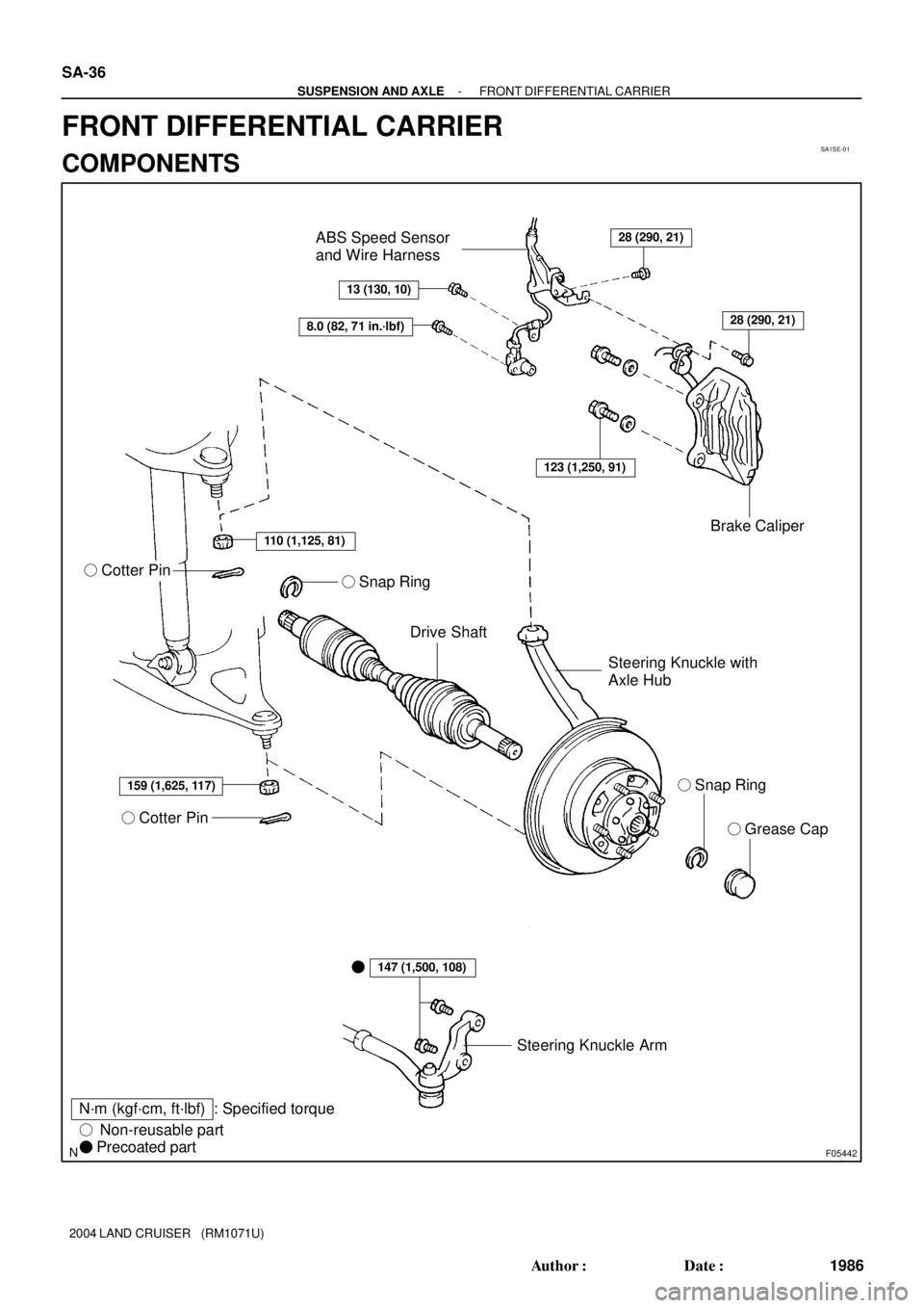
SA1SE-01
F05442
� Grease Cap
Steering Knuckle Arm
� Cotter Pin
Drive Shaft
N´m (kgf´cm, ft´lbf)� Snap Ring Steering Knuckle with
Axle HubBrake Caliper ABS Speed Sensor
and Wire Harness
� Cotter Pin
: Specified torque
� Non-reusable part
� Precoated part
28 (290, 21)
13 (130, 10)
8.0 (82, 71 in.´lbf)
110 (1,125, 81)
159 (1,625, 117)
147 (1,500, 108)
123 (1,250, 91)
28 (290, 21)
� � Snap Ring
SA-36
- SUSPENSION AND AXLEFRONT DIFFERENTIAL CARRIER
1986 Author�: Date�:
2004 LAND CRUISER (RM1071U)
FRONT DIFFERENTIAL CARRIER
COMPONENTS