1998 OPEL FRONTERA turn signal
[x] Cancel search: turn signalPage 2271 of 6000
7A1–26
TRANSMISSION CONTROL SYSTEM (4L30–E)
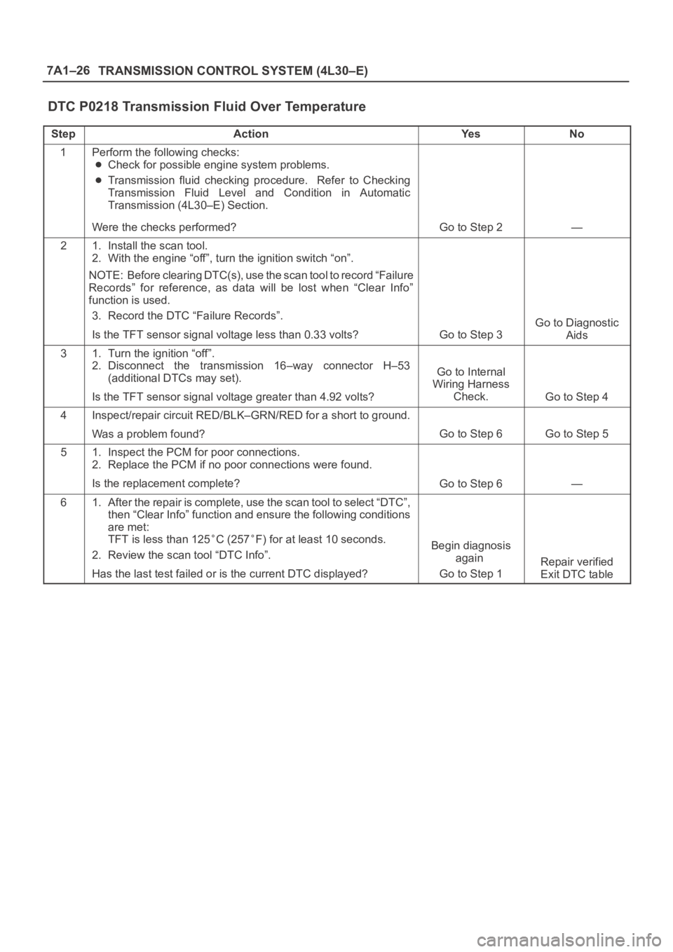
DTC P0218 Transmission Fluid Over Temperature
StepActionYe sNo
1Perform the following checks:
Check for possible engine system problems.
Transmission fluid checking procedure. Refer to Checking
Transmission Fluid Level and Condition in Automatic
Transmission (4L30–E) Section.
Were the checks performed?
Go to Step 2—
21. Install the scan tool.
2. With the engine “off”, turn the ignition switch “on”.
NOTE: Before clearing DTC(s), use the scan tool to record “Failure
Records” for reference, as data will be lost when “Clear Info”
function is used.
3. Record the DTC “Failure Records”.
Is the TFT sensor signal voltage less than 0.33 volts?
Go to Step 3
Go to Diagnostic
Aids
31. Turn the ignition “off”.
2. Disconnect the transmission 16–way connector H–53
(additional DTCs may set).
Is the TFT sensor signal voltage greater than 4.92 volts?
Go to Internal
Wiring Harness
Check.
Go to Step 4
4Inspect/repair circuit RED/BLK–GRN/RED for a short to ground.
Was a problem found?
Go to Step 6Go to Step 5
51. Inspect the PCM for poor connections.
2. Replace the PCM if no poor connections were found.
Is the replacement complete?
Go to Step 6—
61. After the repair is complete, use the scan tool to select “DTC”,
then “Clear Info” function and ensure the following conditions
are met:
TFT is less than 125
C (257F) for at least 10 seconds.
2. Review the scan tool “DTC Info”.
Has the last test failed or is the current DTC displayed?Begin diagnosis
again
Go to Step 1
Repair verified
Exit DTC table
Page 2276 of 6000
TRANSMISSION CONTROL SYSTEM (4L30–E)7A1–31
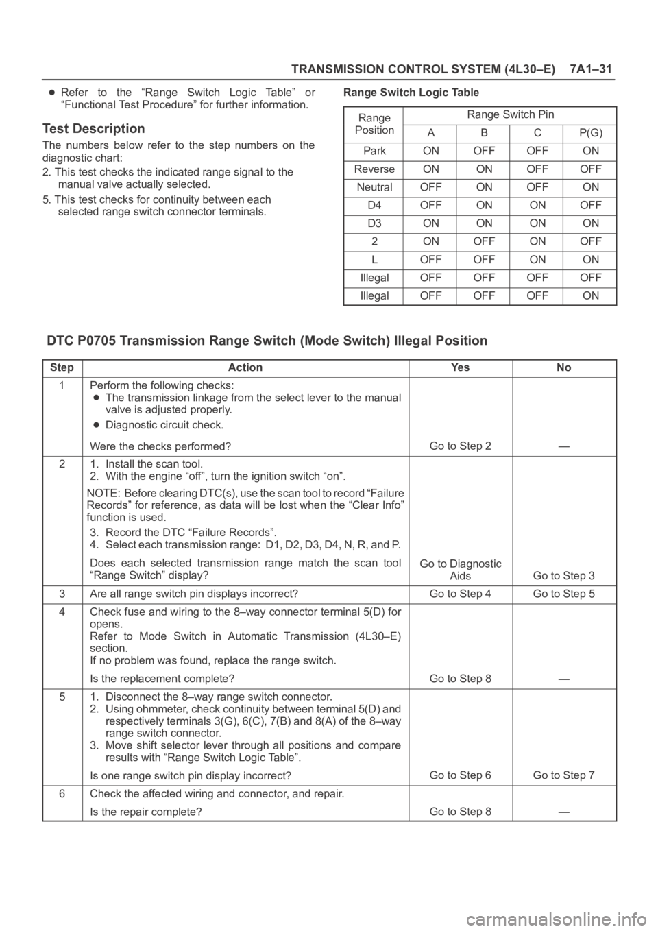
Refer to the “Range Switch Logic Table” or
“Functional Test Procedure” for further information.
Test Description
The numbers below refer to the step numbers on the
diagnostic chart:
2. This test checks the indicated range signal to the
manual valve actually selected.
5. This test checks for continuity between each
selected range switch connector terminals.Range Switch Logic Table
Range
Range Switch Ping
PositionABCP(G)
ParkONOFFOFFON
ReverseONONOFFOFF
NeutralOFFONOFFON
D4OFFONONOFF
D3ONONONON
2ONOFFONOFF
LOFFOFFONON
IllegalOFFOFFOFFOFF
IllegalOFFOFFOFFON
DTC P0705 Transmission Range Switch (Mode Switch) Illegal Position
StepActionYe sNo
1Perform the following checks:
The transmission linkage from the select lever to the manual
valve is adjusted properly.
Diagnostic circuit check.
Were the checks performed?
Go to Step 2—
21. Install the scan tool.
2. With the engine “off”, turn the ignition switch “on”.
NOTE: Before clearing DTC(s), use the scan tool to record “Failure
Records” for reference, as data will be lost when the “Clear Info”
function is used.
3. Record the DTC “Failure Records”.
4. Select each transmission range: D1, D2, D3, D4, N, R, and P.
Does each selected transmission range match the scan tool
“Range Switch” display?
Go to Diagnostic
Aids
Go to Step 3
3Are all range switch pin displays incorrect?Go to Step 4Go to Step 5
4Check fuse and wiring to the 8–way connector terminal 5(D) for
opens.
Refer to Mode Switch in Automatic Transmission (4L30–E)
section.
If no problem was found, replace the range switch.
Is the replacement complete?
Go to Step 8—
51. Disconnect the 8–way range switch connector.
2. Using ohmmeter, check continuity between terminal 5(D) and
respectively terminals 3(G), 6(C), 7(B) and 8(A) of the 8–way
range switch connector.
3. Move shift selector lever through all positions and compare
results with “Range Switch Logic Table”.
Is one range switch pin display incorrect?
Go to Step 6Go to Step 7
6Check the affected wiring and connector, and repair.
Is the repair complete?
Go to Step 8—
Page 2279 of 6000
7A1–34
TRANSMISSION CONTROL SYSTEM (4L30–E)
Diagnostic Aids
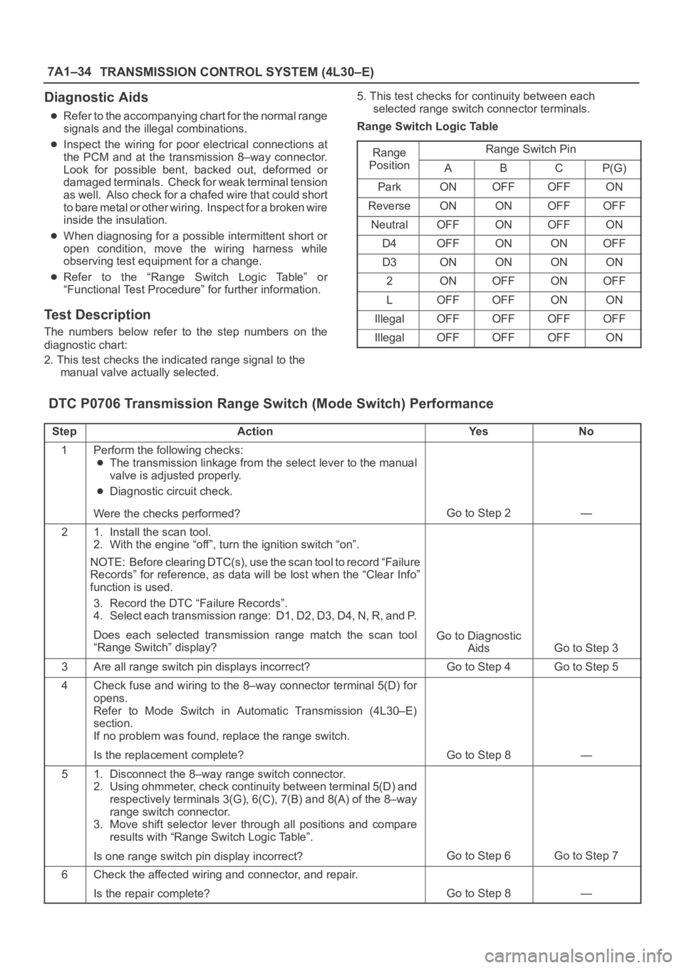
Refer to the accompanying chart for the normal range
signals and the illegal combinations.
Inspect the wiring for poor electrical connections at
the PCM and at the transmission 8–way connector.
Look for possible bent, backed out, deformed or
damaged terminals. Check for weak terminal tension
as well. Also check for a chafed wire that could short
to bare metal or other wiring. Inspect for a broken wire
inside the insulation.
When diagnosing for a possible intermittent short or
open condition, move the wiring harness while
observing test equipment for a change.
Refer to the “Range Switch Logic Table” or
“Functional Test Procedure” for further information.
Test Description
The numbers below refer to the step numbers on the
diagnostic chart:
2. This test checks the indicated range signal to the
manual valve actually selected.5. This test checks for continuity between each
selected range switch connector terminals.
Range Switch Logic Table
Range
Range Switch Ping
PositionABCP(G)
ParkONOFFOFFON
ReverseONONOFFOFF
NeutralOFFONOFFON
D4OFFONONOFF
D3ONONONON
2ONOFFONOFF
LOFFOFFONON
IllegalOFFOFFOFFOFF
IllegalOFFOFFOFFON
DTC P0706 Transmission Range Switch (Mode Switch) Performance
StepActionYe sNo
1Perform the following checks:
The transmission linkage from the select lever to the manual
valve is adjusted properly.
Diagnostic circuit check.
Were the checks performed?
Go to Step 2—
21. Install the scan tool.
2. With the engine “off”, turn the ignition switch “on”.
NOTE: Before clearing DTC(s), use the scan tool to record “Failure
Records” for reference, as data will be lost when the “Clear Info”
function is used.
3. Record the DTC “Failure Records”.
4. Select each transmission range: D1, D2, D3, D4, N, R, and P.
Does each selected transmission range match the scan tool
“Range Switch” display?
Go to Diagnostic
Aids
Go to Step 3
3Are all range switch pin displays incorrect?Go to Step 4Go to Step 5
4Check fuse and wiring to the 8–way connector terminal 5(D) for
opens.
Refer to Mode Switch in Automatic Transmission (4L30–E)
section.
If no problem was found, replace the range switch.
Is the replacement complete?
Go to Step 8—
51. Disconnect the 8–way range switch connector.
2. Using ohmmeter, check continuity between terminal 5(D) and
respectively terminals 3(G), 6(C), 7(B) and 8(A) of the 8–way
range switch connector.
3. Move shift selector lever through all positions and compare
results with “Range Switch Logic Table”.
Is one range switch pin display incorrect?
Go to Step 6Go to Step 7
6Check the affected wiring and connector, and repair.
Is the repair complete?
Go to Step 8—
Page 2282 of 6000
TRANSMISSION CONTROL SYSTEM (4L30–E)7A1–37
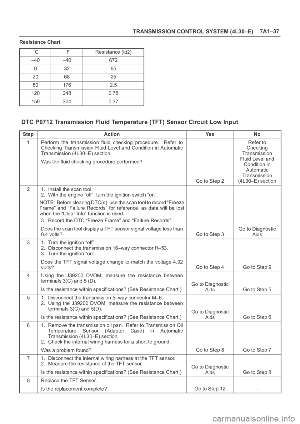
Resistance Chart
CFResistance (k)
–40–40672
03265
206825
801762.5
1202480.78
1503040.37
DTC P0712 Transmission Fluid Temperature (TFT) Sensor Circuit Low Input
StepActionYe sNo
1Perform the transmission fluid checking procedure. Refer to
Checking Transmission Fluid Level and Condition in Automatic
Transmission (4L30–E) section.
Was the fluid checking procedure performed?
Go to Step 2
Refer to
Checking
Transmission
Fluid Level and
Condition in
Automatic
Transmission
(4L30–E) section
21. Install the scan tool.
2. With the engine “off”, turn the ignition switch “on”.
NOTE: Before clearing DTC(s), use the scan tool to record “Freeze
Frame” and “Failure Records” for reference, as data will be lost
when the “Clear Info” function is used.
3. Record the DTC “Freeze Frame” and “Failure Records”.
Does the scan tool display a TFT sensor signal voltage less than
0.4 volts?
Go to Step 3
Go to Diagnostic
Aids
31. Turn the ignition “off”.
2. Disconnect the transmission 16–way connector H–53.
3. Turn the ignition “on”.
Does the TFT signal voltage change to match the voltage 4.92
volts?
Go to Step 4Go to Step 9
4Using the J39200 DVOM, measure the resistance between
terminals 3(C) and 5 (D).
Is the resistance within specifications? (See Resistance Chart.)
Go to Diagnostic
Aids
Go to Step 5
51. Disconnect the transmission 5–way connector M–6.
2. Using the J39200 DVOM, measure the resistance between
terminals 3(C) and 5(D).
Is the resistance within specifications? (See Resistance Chart.)
Go to Diagnostic
Aids
Go to Step 6
61. Remove the transmission oil pan. Refer to Transmission Oil
Temperature Sensor (Adapter Case) in Automatic
Transmission (4L30–E) section.
2. Check the internal wiring harness for a short to ground.
Was a problem found?
Go to Step 8Go to Step 7
71. Disconnect the internal wiring harness at the TFT sensor.
2. Measure the resistance of the TFT sensor.
Is the resistance within specifications? (See Resistance Chart.)
Go to Diagnostic
Aids
Go to Step 8
8Replace the TFT Sensor.
Is the replacement complete?
Go to Step 12—
Page 2285 of 6000
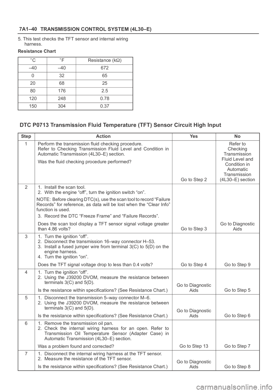
7A1–40
TRANSMISSION CONTROL SYSTEM (4L30–E)
5. This test checks the TFT sensor and internal wiring
harness.
Resistance Chart
CFResistance (k)
–40–40672
03265
206825
801762.5
1202480.78
1503040.37
DTC P0713 Transmission Fluid Temperature (TFT) Sensor Circuit High Input
StepActionYe sNo
1Perform the transmission fluid checking procedure.
Refer to Checking Transmission Fluid Level and Condition in
Automatic Transmission (4L30–E) section.
Was the fluid checking procedure performed?
Go to Step 2
Refer to
Checking
Transmission
Fluid Level and
Condition in
Automatic
Transmission
(4L30–E) section
21. Install the scan tool.
2. With the engine “off”, turn the ignition switch “on”.
NOTE: Before clearing DTC(s), use the scan tool to record “Failure
Records” for reference, as data will be lost when the “Clear Info”
function is used.
3. Record the DTC “Freeze Frame” and “Failure Records”.
Does the scan tool display a TFT sensor signal voltage greater
than 4.86 volts?
Go to Step 3
Go to Diagnostic
Aids
31. Turn the ignition “off”.
2. Disconnect the transmission 16–way connector H–53.
3. Install a fused jumper wire from terminal 3(C) to 5(D) on the
engine harness.
4. Turn the ignition “on”.
Does the TFT signal voltage drop to less than 0.4 volts?
Go to Step 4Go to Step 9
41. Turn the ignition “off”.
2. Using the J39200 DVOM, measure the resistance between
terminals 3(C) and 5(D).
Is the resistance within specifications? (See Resistance Chart.)
Go to Diagnostic
Aids
Go to Step 5
51. Disconnect the transmission 5–way connector M–6.
2. Using the J39200 DVOM, measure the resistance between
terminals 3(C) and 5(D).
Is the resistance within specifications? (See Resistance Chart.)
Go to Diagnostic
Aids
Go to Step 6
61. Remove the transmission oil pan.
2. Check the internal wiring harness for an open. Refer to
Transmission Oil Temperature Sensor (Adapter Case) in
Automatic Transmission (4L30–E) section.
Was a problem found and corrected?
Go to Step 13Go to Step 7
71. Disconnect the internal wiring harness at the TFT sensor.
2. Measure the resistance of the TFT sensor.
Is the resistance within specifications? (See Resistance Chart.)
Go to Diagnostic
Aids
Go to Step 8
Page 2540 of 6000
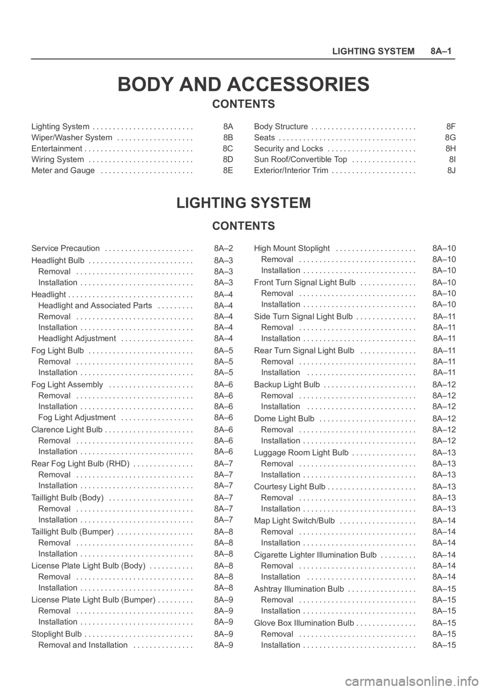
LIGHTING SYSTEM8A–1
BODY AND ACCESSORIES
CONTENTS
Lighting System 8A. . . . . . . . . . . . . . . . . . . . . . . . .
Wiper/Washer System 8B. . . . . . . . . . . . . . . . . . .
Entertainment 8C. . . . . . . . . . . . . . . . . . . . . . . . . . .
Wiring System 8D. . . . . . . . . . . . . . . . . . . . . . . . . .
Meter and Gauge 8E. . . . . . . . . . . . . . . . . . . . . . . Body Structure 8F. . . . . . . . . . . . . . . . . . . . . . . . . .
Seats 8G. . . . . . . . . . . . . . . . . . . . . . . . . . . . . . . . . .
Security and Locks 8H. . . . . . . . . . . . . . . . . . . . . .
Sun Roof/Convertible Top 8I. . . . . . . . . . . . . . . .
Exterior/Interior Trim 8J. . . . . . . . . . . . . . . . . . . . .
LIGHTING SYSTEM
CONTENTS
Service Precaution 8A–2. . . . . . . . . . . . . . . . . . . . . .
Headlight Bulb 8A–3. . . . . . . . . . . . . . . . . . . . . . . . . .
Removal 8A–3. . . . . . . . . . . . . . . . . . . . . . . . . . . . .
Installation 8A–3. . . . . . . . . . . . . . . . . . . . . . . . . . . .
Headlight 8A–4. . . . . . . . . . . . . . . . . . . . . . . . . . . . . . .
Headlight and Associated Parts 8A–4. . . . . . . . .
Removal 8A–4. . . . . . . . . . . . . . . . . . . . . . . . . . . . .
Installation 8A–4. . . . . . . . . . . . . . . . . . . . . . . . . . . .
Headlight Adjustment 8A–4. . . . . . . . . . . . . . . . . .
Fog Light Bulb 8A–5. . . . . . . . . . . . . . . . . . . . . . . . . .
Removal 8A–5. . . . . . . . . . . . . . . . . . . . . . . . . . . . .
Installation 8A–5. . . . . . . . . . . . . . . . . . . . . . . . . . . .
Fog Light Assembly 8A–6. . . . . . . . . . . . . . . . . . . . .
Removal 8A–6. . . . . . . . . . . . . . . . . . . . . . . . . . . . .
Installation 8A–6. . . . . . . . . . . . . . . . . . . . . . . . . . . .
Fog Light Adjustment 8A–6. . . . . . . . . . . . . . . . . .
Clarence Light Bulb 8A–6. . . . . . . . . . . . . . . . . . . . . .
Removal 8A–6. . . . . . . . . . . . . . . . . . . . . . . . . . . . .
Installation 8A–6. . . . . . . . . . . . . . . . . . . . . . . . . . . .
Rear Fog Light Bulb (RHD) 8A–7. . . . . . . . . . . . . . .
Removal 8A–7. . . . . . . . . . . . . . . . . . . . . . . . . . . . .
Installation 8A–7. . . . . . . . . . . . . . . . . . . . . . . . . . . .
Taillight Bulb (Body) 8A–7. . . . . . . . . . . . . . . . . . . . .
Removal 8A–7. . . . . . . . . . . . . . . . . . . . . . . . . . . . .
Installation 8A–7. . . . . . . . . . . . . . . . . . . . . . . . . . . .
Taillight Bulb (Bumper) 8A–8. . . . . . . . . . . . . . . . . . .
Removal 8A–8. . . . . . . . . . . . . . . . . . . . . . . . . . . . .
Installation 8A–8. . . . . . . . . . . . . . . . . . . . . . . . . . . .
License Plate Light Bulb (Body) 8A–8. . . . . . . . . . .
Removal 8A–8. . . . . . . . . . . . . . . . . . . . . . . . . . . . .
Installation 8A–8. . . . . . . . . . . . . . . . . . . . . . . . . . . .
License Plate Light Bulb (Bumper) 8A–9. . . . . . . . .
Removal 8A–9. . . . . . . . . . . . . . . . . . . . . . . . . . . . .
Installation 8A–9. . . . . . . . . . . . . . . . . . . . . . . . . . . .
Stoplight Bulb 8A–9. . . . . . . . . . . . . . . . . . . . . . . . . . .
Removal and Installation 8A–9. . . . . . . . . . . . . . . High Mount Stoplight 8A–10. . . . . . . . . . . . . . . . . . . .
Removal 8A–10. . . . . . . . . . . . . . . . . . . . . . . . . . . . .
Installation 8A–10. . . . . . . . . . . . . . . . . . . . . . . . . . . .
Front Turn Signal Light Bulb 8A–10. . . . . . . . . . . . . .
Removal 8A–10. . . . . . . . . . . . . . . . . . . . . . . . . . . . .
Installation 8A–10. . . . . . . . . . . . . . . . . . . . . . . . . . . .
Side Turn Signal Light Bulb 8A–11. . . . . . . . . . . . . . .
Removal 8A–11. . . . . . . . . . . . . . . . . . . . . . . . . . . . .
Installation 8A–11. . . . . . . . . . . . . . . . . . . . . . . . . . . .
Rear Turn Signal Light Bulb 8A–11. . . . . . . . . . . . . .
Removal 8A–11. . . . . . . . . . . . . . . . . . . . . . . . . . . . .
Installation 8A–11. . . . . . . . . . . . . . . . . . . . . . . . . . .
Backup Light Bulb 8A–12. . . . . . . . . . . . . . . . . . . . . . .
Removal 8A–12. . . . . . . . . . . . . . . . . . . . . . . . . . . . .
Installation 8A–12
. . . . . . . . . . . . . . . . . . . . . . . . . . .
Dome Light Bulb 8A–12. . . . . . . . . . . . . . . . . . . . . . . .
Removal 8A–12. . . . . . . . . . . . . . . . . . . . . . . . . . . . .
Installation 8A–12. . . . . . . . . . . . . . . . . . . . . . . . . . . .
Luggage Room Light Bulb 8A–13. . . . . . . . . . . . . . . .
Removal 8A–13. . . . . . . . . . . . . . . . . . . . . . . . . . . . .
Installation 8A–13. . . . . . . . . . . . . . . . . . . . . . . . . . . .
Courtesy Light Bulb 8A–13. . . . . . . . . . . . . . . . . . . . . .
Removal 8A–13. . . . . . . . . . . . . . . . . . . . . . . . . . . . .
Installation 8A–13. . . . . . . . . . . . . . . . . . . . . . . . . . . .
Map Light Switch/Bulb 8A–14. . . . . . . . . . . . . . . . . . .
Removal 8A–14. . . . . . . . . . . . . . . . . . . . . . . . . . . . .
Installation 8A–14. . . . . . . . . . . . . . . . . . . . . . . . . . . .
Cigarette Lighter Illumination Bulb 8A–14. . . . . . . . .
Removal 8A–14. . . . . . . . . . . . . . . . . . . . . . . . . . . . .
Installation 8A–14. . . . . . . . . . . . . . . . . . . . . . . . . . .
Ashtray Illumination Bulb 8A–15. . . . . . . . . . . . . . . . .
Removal 8A–15. . . . . . . . . . . . . . . . . . . . . . . . . . . . .
Installation 8A–15. . . . . . . . . . . . . . . . . . . . . . . . . . . .
Glove Box Illumination Bulb 8A–15. . . . . . . . . . . . . . .
Removal 8A–15. . . . . . . . . . . . . . . . . . . . . . . . . . . . .
Installation 8A–15. . . . . . . . . . . . . . . . . . . . . . . . . . . .
Page 2541 of 6000
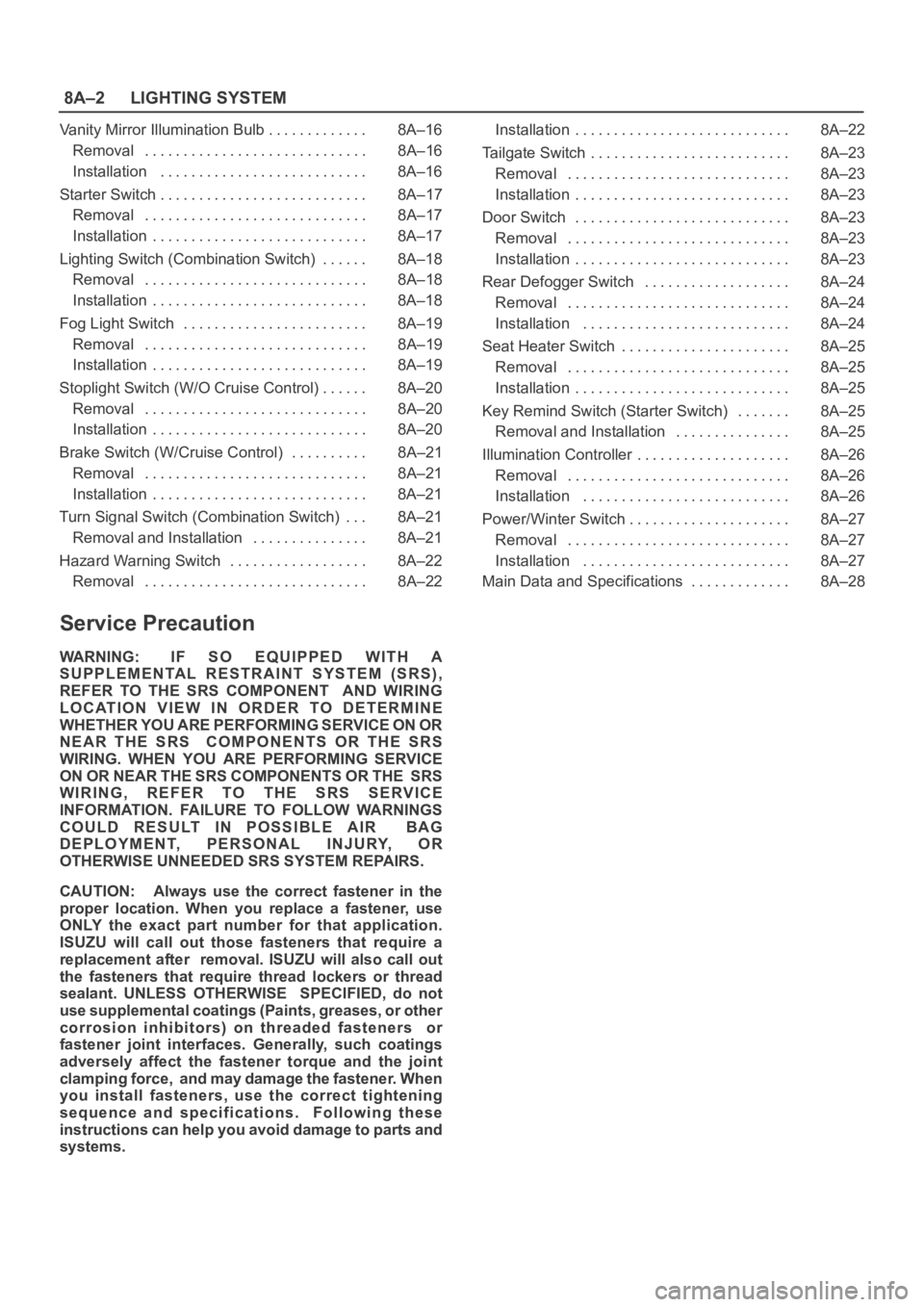
8A–2LIGHTING SYSTEM
Vanity Mirror Illumination Bulb 8A–16. . . . . . . . . . . . .
Removal 8A–16. . . . . . . . . . . . . . . . . . . . . . . . . . . . .
Installation 8A–16. . . . . . . . . . . . . . . . . . . . . . . . . . .
Starter Switch 8A–17. . . . . . . . . . . . . . . . . . . . . . . . . . .
Removal 8A–17. . . . . . . . . . . . . . . . . . . . . . . . . . . . .
Installation 8A–17. . . . . . . . . . . . . . . . . . . . . . . . . . . .
Lighting Switch (Combination Switch) 8A–18. . . . . .
Removal 8A–18. . . . . . . . . . . . . . . . . . . . . . . . . . . . .
Installation 8A–18. . . . . . . . . . . . . . . . . . . . . . . . . . . .
Fog Light Switch 8A–19. . . . . . . . . . . . . . . . . . . . . . . .
Removal 8A–19. . . . . . . . . . . . . . . . . . . . . . . . . . . . .
Installation 8A–19. . . . . . . . . . . . . . . . . . . . . . . . . . . .
Stoplight Switch (W/O Cruise Control) 8A–20. . . . . .
Removal 8A–20. . . . . . . . . . . . . . . . . . . . . . . . . . . . .
Installation 8A–20. . . . . . . . . . . . . . . . . . . . . . . . . . . .
Brake Switch (W/Cruise Control) 8A–21. . . . . . . . . .
Removal 8A–21. . . . . . . . . . . . . . . . . . . . . . . . . . . . .
Installation 8A–21. . . . . . . . . . . . . . . . . . . . . . . . . . . .
Turn Signal Switch (Combination Switch) 8A–21. . .
Removal and Installation 8A–21. . . . . . . . . . . . . . .
Hazard Warning Switch 8A–22. . . . . . . . . . . . . . . . . .
Removal 8A–22. . . . . . . . . . . . . . . . . . . . . . . . . . . . . Installation 8A–22. . . . . . . . . . . . . . . . . . . . . . . . . . . .
Tailgate Switch 8A–23. . . . . . . . . . . . . . . . . . . . . . . . . .
Removal 8A–23. . . . . . . . . . . . . . . . . . . . . . . . . . . . .
Installation 8A–23. . . . . . . . . . . . . . . . . . . . . . . . . . . .
Door Switch 8A–23. . . . . . . . . . . . . . . . . . . . . . . . . . . .
Removal 8A–23. . . . . . . . . . . . . . . . . . . . . . . . . . . . .
Installation 8A–23. . . . . . . . . . . . . . . . . . . . . . . . . . . .
Rear Defogger Switch 8A–24. . . . . . . . . . . . . . . . . . .
Removal 8A–24. . . . . . . . . . . . . . . . . . . . . . . . . . . . .
Installation 8A–24. . . . . . . . . . . . . . . . . . . . . . . . . . .
Seat Heater Switch 8A–25. . . . . . . . . . . . . . . . . . . . . .
Removal 8A–25. . . . . . . . . . . . . . . . . . . . . . . . . . . . .
Installation 8A–25. . . . . . . . . . . . . . . . . . . . . . . . . . . .
Key Remind Switch (Starter Switch) 8A–25. . . . . . .
Removal and Installation 8A–25. . . . . . . . . . . . . . .
Illumination Controller 8A–26. . . . . . . . . . . . . . . . . . . .
Removal 8A–26. . . . . . . . . . . . . . . . . . . . . . . . . . . . .
Installation 8A–26. . . . . . . . . . . . . . . . . . . . . . . . . . .
Power/Winter Switch 8A–27. . . . . . . . . . . . . . . . . . . . .
Removal 8A–27. . . . . . . . . . . . . . . . . . . . . . . . . . . . .
Installation 8A–27. . . . . . . . . . . . . . . . . . . . . . . . . . .
Main Data and Specifications 8A–28. . . . . . . . . . . . .
Service Precaution
WARNING: IF SO EQUIPPED WITH A
SUPPLEMENTAL RESTRAINT SYSTEM (SRS),
REFER TO THE SRS COMPONENT AND WIRING
LOCATION VIEW IN ORDER TO DETERMINE
WHETHER YOU ARE PERFORMING SERVICE ON OR
NEAR THE SRS COMPONENTS OR THE SRS
WIRING. WHEN YOU ARE PERFORMING SERVICE
ON OR NEAR THE SRS COMPONENTS OR THE SRS
WIRING, REFER TO THE SRS SERVICE
INFORMATION. FAILURE TO FOLLOW WARNINGS
COULD RESULT IN POSSIBLE AIR BAG
DEPLOYMENT, PERSONAL INJURY, OR
OTHERWISE UNNEEDED SRS SYSTEM REPAIRS.
CAUTION: Always use the correct fastener in the
proper location. When you replace a fastener, use
ONLY the exact part number for that application.
ISUZU will call out those fasteners that require a
replacement after removal. ISUZU will also call out
the fasteners that require thread lockers or thread
sealant. UNLESS OTHERWISE SPECIFIED, do not
use supplemental coatings (Paints, greases, or other
corrosion inhibitors) on threaded fasteners or
fastener joint interfaces. Generally, such coatings
adversely affect the fastener torque and the joint
clamping force, and may damage the fastener. When
you install fasteners, use the correct tightening
sequence and specifications. Following these
instructions can help you avoid damage to parts and
systems.
Page 2549 of 6000
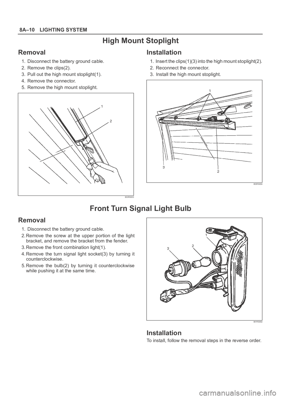
8A–10LIGHTING SYSTEM
High Mount Stoplight
Removal
1. Disconnect the battery ground cable.
2. Remove the clips(2).
3. Pull out the high mount stoplight(1).
4. Remove the connector.
5. Remove the high mount stoplight.
803RS003
Installation
1. Insert the clips(1)(3) into the high mount stoplight(2).
2. Reconnect the connector.
3. Install the high mount stoplight.
803RS004
Front Turn Signal Light Bulb
Removal
1. Disconnect the battery ground cable.
2. Remove the screw at the upper portion of the light
bracket, and remove the bracket from the fender.
3. Remove the front combination light(1).
4. Remove the turn signal light socket(3) by turning it
counterclockwise.
5. Remove the bulb(2) by turning it counterclockwise
while pushing it at the same time.
801RS002
Installation
To install, follow the removal steps in the reverse order.