1998 OPEL FRONTERA turn signal
[x] Cancel search: turn signalPage 1932 of 6000
6E–39 4JX1–TC ENGINE DRIVEABILITY AND EMISSIONS
Engine Control Module ECM
Diagnosis
To read and clear diagnostic trouble codes, use a Tech 2.
IMPORTANT:Use of a Tech 2 is recommended to clear
diagnostic trouble codes from the ECM memory.
Diagnostic trouble codes can also be cleared by turning
the ignition “OFF” and disconnecting the battery power
from the ECM for 30 seconds. Turning off the ignition and
disconnecting the battery power from the ECM will cause
all diagnostic information in the ECM memory to be
cleared. Therefore, all the diagnostic tests will have to be
re-run.
Since the ECM can have a failure which may affect only
one circuit, following the diagnostic procedures in this
section will determine which circuit has a problem and
where it is.
If a diagnostic chart indicates that the ECM connections
or the ECM is the cause of a problem, and the ECM is
replaced, but this does not correct the problem, one of the
following may be the reason:
There is a problem with the ECM terminal
connections. The terminals may have to be removed
from the connector in order to check them properly.
The problem is intermittent. This means that the
problem is not present at the time the system is being
checked. In this case, refer to the
Symptoms portion
of the manual and make a careful physical inspection
of all components and wiring associated with the
affected system.
There is a shorted solenoid, relay coil, or harness.
Solenoids and relays are turned “ON” and “OFF” by
the ECM using internal electronic switches called
drivers. A shorted solenoid, relay coil, or harness will
not damage the ECM but will cause the solenoid or
relay to be inoperative.
Multiple ECM Information Sensor
DTCS Set
Circuit Description
The Engine Control Module ECM monitors various
sensors to determine the engine operating conditions.
The ECM controls fuel delivery, spark advance,
transmission operation, and emission control device
operation based on the sensor inputs.
The ECM provides a sensor ground to all of the sensors.
The ECM applies 5 volts through a pull-up resistor, and
determines the status of the following sensors by
monitoring the voltage present between the 5-volt supply
and the resistor:
The fuel temperature (FT) sensor
The engine coolant temperature (ECT) sensor
The Intake air temperature (IAT) sensor
The ECM provides the following sensors with a 5-volt
reference and a sensor ground signal:
The Intake throttle position sensor
The manifold absolute pressure sensor
The rail pressure sensor
The accelerator position sensor
The oil temperature sensor
The camshaft position sensor
The crankshaft position sensor
The EGR pressure sensor
The ECM monitors the signals from these sensors in
order to determine their operating status.
Diagnostic Aids
IMPORTANT:Be sure to inspect ECM and engine
grounds for being secure and clean.
A short to voltage in one of the sensor input circuits may
cause one or more of the following DTCs to be set:
P0337
P0342
P1193
P1404
P1405
P1488
IMPORTANT:If a sensor input circuit has been shorted
to voltage, ensure that the sensor is not damaged. A
damaged sensor will continue to indicate a high or low
voltage after the affected circuit has been repaired. If the
sensor has been damaged, replace it.
An open in the sensor ground circuit between the ECM
and the splice will cause one or more of the following
DTCs to be set:
P0337
P0342
P0117
A short to ground in the 5-volt reference A or B circuit will
cause one or more of the following DTCs to be set:
P0112
P0117
P0182
P0197
An open in the 5-volt reference circuit A, between the
ECM and the splice will cause one or more of the following
DTCs to be set:
P0107
P0405
P1194
P0122
An open in the 5-volt reference circuit B, between the
ECM and the splice will cause one or more of the following
DTCs to be set:
P1485
Check for the following conditions:
Poor connection at ECM. Inspect the harness
connectors for backed-out terminals, improper
mating, broken locks, improperly formed or damage
terminals, and a poor terminal-to-wire connection.
Damaged harness. Inspect the wiring harness for
damage. If the harness is not damaged, observe an
affected sensor’s displayed value on the Tech 2 with
the ignition “ON” and the engine “OFF” while you
move the connectors and the wiring harnesses
related to the following sensors:
ECT Sensor
Page 1949 of 6000
6E–56
4JX1–TC ENGINE DRIVEABILITY AND EMISSIONS
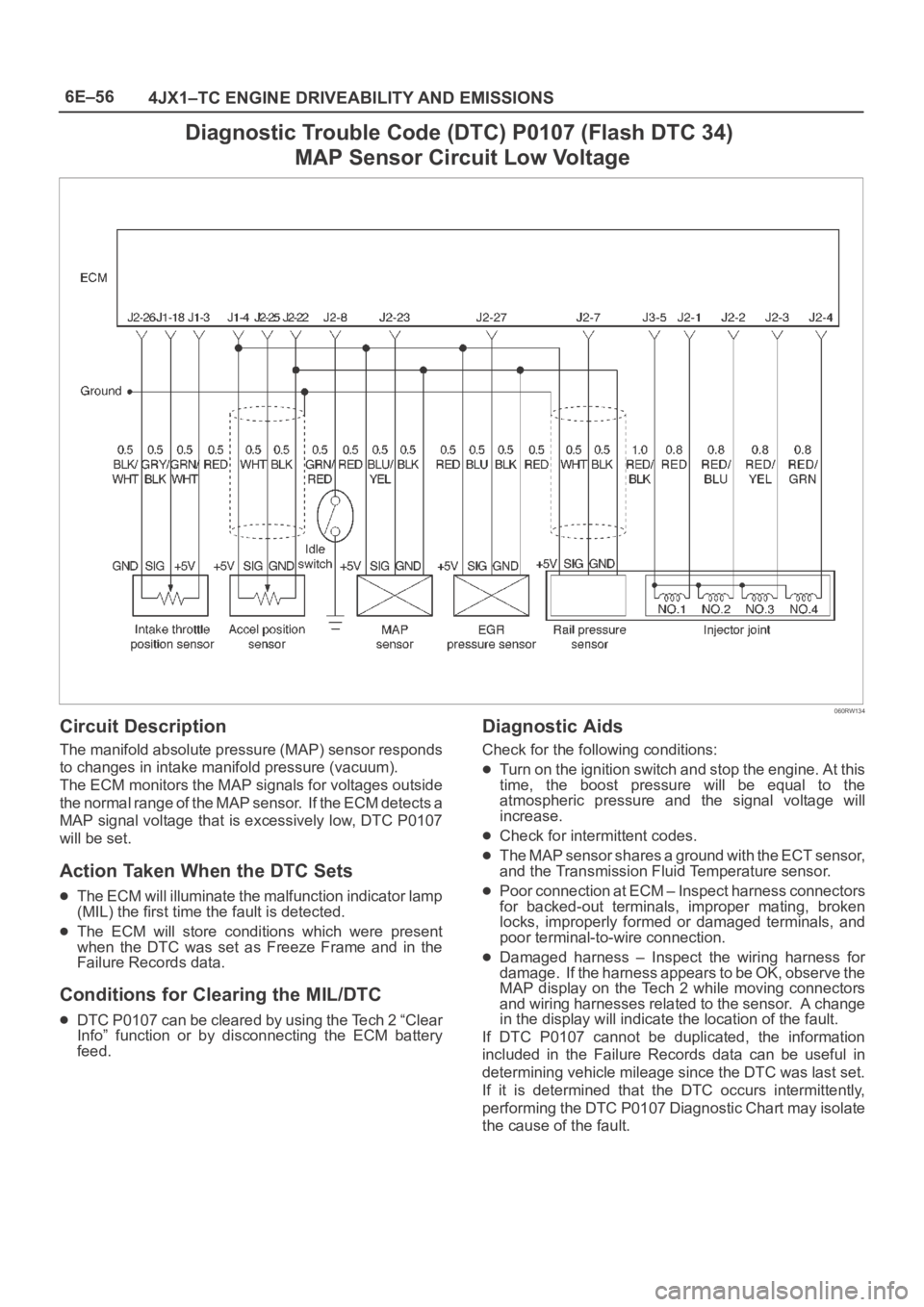
Diagnostic Trouble Code (DTC) P0107 (Flash DTC 34)
MAP Sensor Circuit Low Voltage
060RW134
Circuit Description
The manifold absolute pressure (MAP) sensor responds
to changes in intake manifold pressure (vacuum).
The ECM monitors the MAP signals for voltages outside
the normal range of the MAP sensor. If the ECM detects a
MAP signal voltage that is excessively low, DTC P0107
will be set.
Action Taken When the DTC Sets
The ECM will illuminate the malfunction indicator lamp
(MIL) the first time the fault is detected.
The ECM will store conditions which were present
when the DTC was set as Freeze Frame and in the
Failure Records data.
Conditions for Clearing the MIL/DTC
DTC P0107 can be cleared by using the Tech 2 “Clear
Info” function or by disconnecting the ECM battery
feed.
Diagnostic Aids
Check for the following conditions:
Turn on the ignition switch and stop the engine. At this
time, the boost pressure will be equal to the
atmospheric pressure and the signal voltage will
increase.
Check for intermittent codes.
The MAP sensor shares a ground with the ECT sensor,
and the Transmission Fluid Temperature sensor.
Poor connection at ECM – Inspect harness connectors
for backed-out terminals, improper mating, broken
locks, improperly formed or damaged terminals, and
poor terminal-to-wire connection.
Damaged harness – Inspect the wiring harness for
damage. If the harness appears to be OK, observe the
MAP display on the Tech 2 while moving connectors
and wiring harnesses related to the sensor. A change
in the display will indicate the location of the fault.
If DTC P0107 cannot be duplicated, the information
included in the Failure Records data can be useful in
determining vehicle mileage since the DTC was last set.
If it is determined that the DTC occurs intermittently,
performing the DTC P0107 Diagnostic Chart may isolate
the cause of the fault.
Page 1950 of 6000
6E–57 4JX1–TC ENGINE DRIVEABILITY AND EMISSIONS
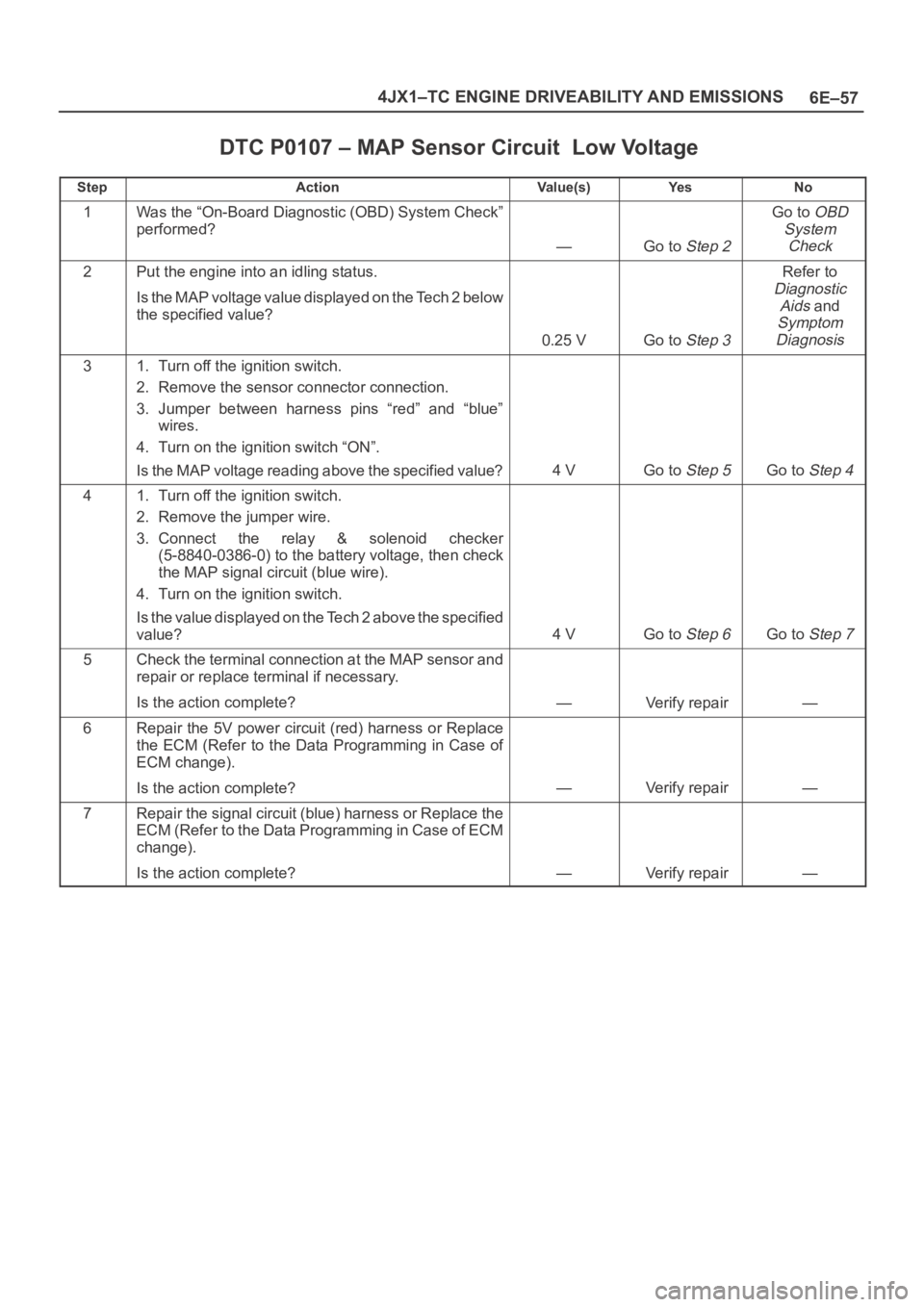
DTC P0107 – MAP Sensor Circuit Low Voltage
StepActionVa l u e ( s )Ye sNo
1Was the “On-Board Diagnostic (OBD) System Check”
performed?
—Go to Step 2
Go to OBD
System
Check
2Put the engine into an idling status.
Is the MAP voltage value displayed on the Tech 2 below
the specified value?
0.25 VGo to Step 3
Refer to
Diagnostic
Aids
and
Symptom
Diagnosis
31. Turn off the ignition switch.
2. Remove the sensor connector connection.
3. Jumper between harness pins “red” and “blue”
wires.
4. Turn on the ignition switch “ON”.
Is the MAP voltage reading above the specified value?
4 VGo to Step 5Go to Step 4
41. Turn off the ignition switch.
2. Remove the jumper wire.
3. Connect the relay & solenoid checker
(5-8840-0386-0) to the battery voltage, then check
the MAP signal circuit (blue wire).
4. Turn on the ignition switch.
Is the value displayed on the Tech 2 above the specified
value?
4 VGo to Step 6Go to Step 7
5Check the terminal connection at the MAP sensor and
repair or replace terminal if necessary.
Is the action complete?
—Verify repair—
6Repair the 5V power circuit (red) harness or Replace
the ECM (Refer to the Data Programming in Case of
ECM change).
Is the action complete?
—Verify repair—
7Repair the signal circuit (blue) harness or Replace the
ECM (Refer to the Data Programming in Case of ECM
change).
Is the action complete?
—Verify repair—
Page 1951 of 6000
6E–58
4JX1–TC ENGINE DRIVEABILITY AND EMISSIONS
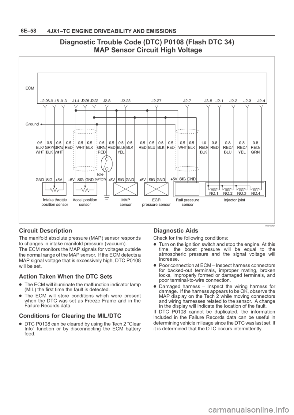
Diagnostic Trouble Code (DTC) P0108 (Flash DTC 34)
MAP Sensor Circuit High Voltage
060RW134
Circuit Description
The manifold absolute pressure (MAP) sensor responds
to changes in intake manifold pressure (vacuum).
The ECM monitors the MAP signals for voltages outside
the normal range of the MAP sensor. If the ECM detects a
MAP signal voltage that is excessively high, DTC P0108
will be set.
Action Taken When the DTC Sets
The ECM will illuminate the malfunction indicator lamp
(MIL) the first time the fault is detected.
The ECM will store conditions which were present
when the DTC was set as Freeze Frame and in the
Failure Records data.
Conditions for Clearing the MIL/DTC
DTC P0108 can be cleared by using the Tech 2 “Clear
Info” function or by disconnecting the ECM battery
feed.
Diagnostic Aids
Check for the following conditions:
Turn on the ignition switch and stop the engine. At this
time, the boost pressure will be equal to the
atmospheric pressure and the signal voltage will
increase.
Poor connection at ECM – Inspect harness connectors
for backed-out terminals, improper mating, broken
locks, improperly formed or damaged terminals, and
poor terminal-to-wire connection.
Damaged harness – Inspect the wiring harness for
damage. If the harness appears to be OK, observe the
MAP display on the Tech 2 while moving connectors
and wiring harnesses related to the sensor. A change
in the display will indicate the location of the fault.
If DTC P0108 cannot be duplicated, the information
included in the Failure Records data can be useful in
determining vehicle mileage since the DTC was last set. If
it is determined that the DTC occurs intermittently.
Page 1952 of 6000
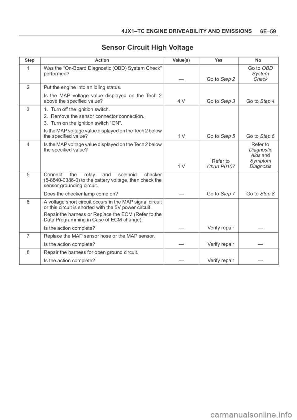
6E–59 4JX1–TC ENGINE DRIVEABILITY AND EMISSIONS
Sensor Circuit High Voltage
StepActionVa l u e ( s )Ye sNo
1Was the “On-Board Diagnostic (OBD) System Check”
performed?
—Go to Step 2
Go to OBD
System
Check
2Put the engine into an idling status.
Is the MAP voltage value displayed on the Tech 2
above the specified value?
4 VGo to Step 3Go to Step 4
31. Turn off the ignition switch.
2. Remove the sensor connector connection.
3. Turn on the ignition switch “ON”.
Is the MAP voltage value displayed on the Tech 2 below
the specified value?
1 VGo to Step 5Go to Step 6
4Is the MAP voltage value displayed on the Tech 2 below
the specified value?
1 V
Refer to
Chart P0107
Refer to
Diagnostic
Aids
and
Symptom
Diagnosis
5Connect the relay and solenoid checker
(5-8840-0386-0) to the battery voltage, then check the
sensor grounding circuit.
Does the checker lamp come on?
—Go to Step 7Go to Step 8
6A voltage short circuit occurs in the MAP signal circuit
or this circuit is shorted with the 5V power circuit.
Repair the harness or Replace the ECM (Refer to the
Data Programming in Case of ECM change).
Is the action complete?
—Verify repair—
7Replace the MAP sensor hose or the MAP sensor.
Is the action complete?
—Verify repair—
8Repair the harness for open ground circuit.
Is the action complete?
—Verify repair—
Page 2007 of 6000
6E–114
4JX1–TC ENGINE DRIVEABILITY AND EMISSIONS
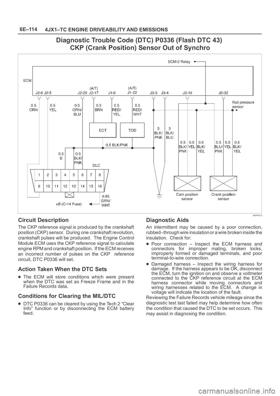
Diagnostic Trouble Code (DTC) P0336 (Flash DTC 43)
CKP (Crank Position) Sensor Out of Synchro
060RW133
Circuit Description
The CKP reference signal is produced by the crankshaft
position (CKP) sensor. During one crankshaft revolution,
crankshaft pulses will be produced. The Engine Control
Module ECM uses the CKP reference signal to calculate
engine RPM and crankshaft position. If the ECM receives
an incorrect number of pulses on the CKP reference
circuit, DTC P0336 will set.
Action Taken When the DTC Sets
The ECM will store conditions which were present
when the DTC was set as Freeze Frame and in the
Failure Records data.
Conditions for Clearing the MIL/DTC
DTC P0336 can be cleared by using the Tech 2 “Clear
Info” function or by disconnecting the ECM battery
feed.
Diagnostic Aids
An intermittent may be caused by a poor connection,
rubbed–through wire insulation or a wire broken inside the
insulation. Check for:
Poor connection – Inspect the ECM harness and
connectors for improper mating, broken locks,
improperly formed or damaged terminals, and poor
terminal-to-wire connection.
Damaged harness – Inspect the wiring harness for
damage. If the harness appears to be OK, disconnect
the ECM, turn the ignition on and observe a voltmeter
connected to the CKP reference circuit at the ECM
harness connector while moving connectors and
wiring harnesses related to the ECM. A change in
voltage will indicate the location of the fault.
Reviewing the Failure Records vehicle mileage since the
diagnostic test last failed may help determine how often
the condition that caused the DTC to be set occurs. This
may assist in diagnosing the condition.
Page 2009 of 6000
6E–116
4JX1–TC ENGINE DRIVEABILITY AND EMISSIONS
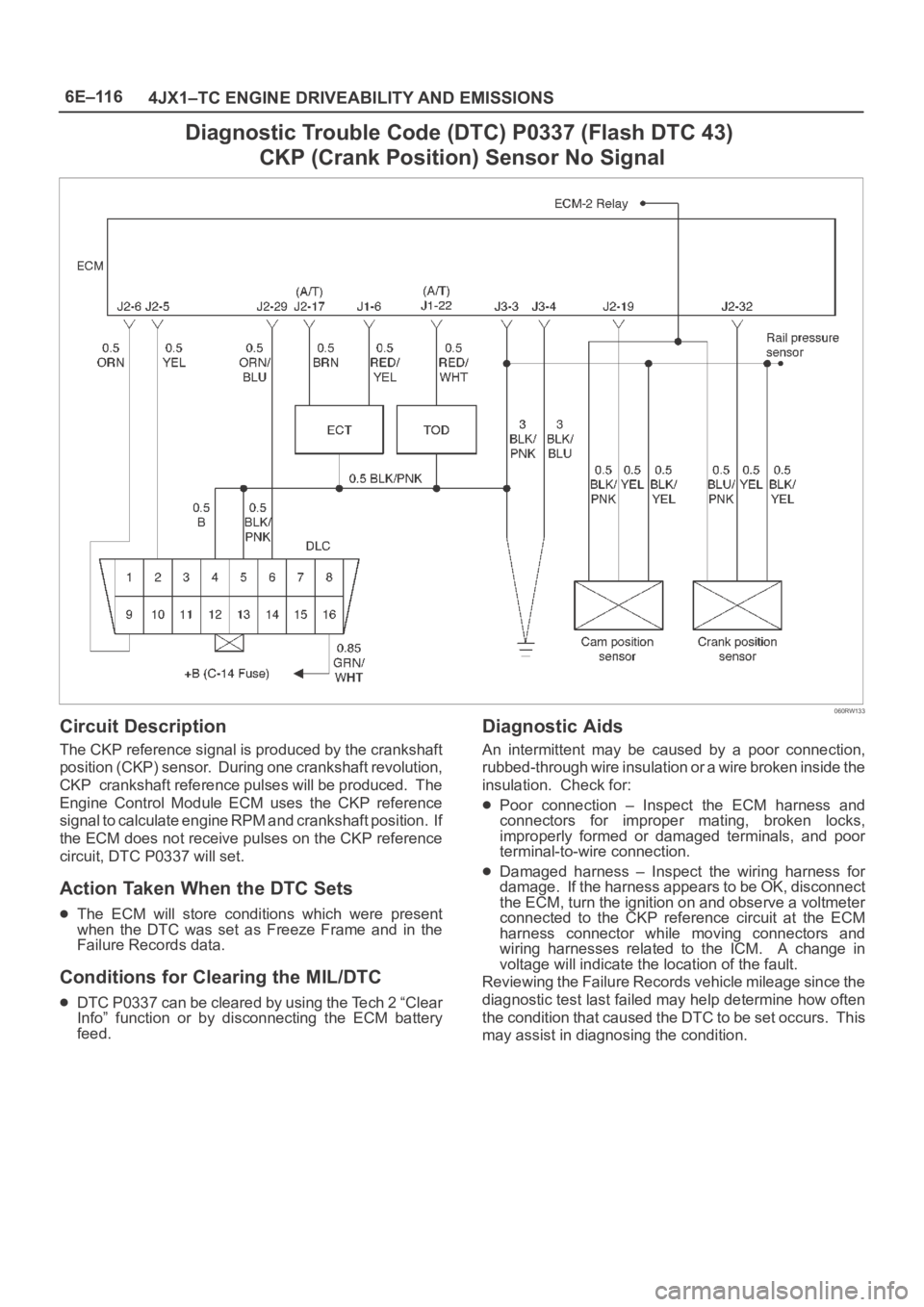
Diagnostic Trouble Code (DTC) P0337 (Flash DTC 43)
CKP (Crank Position) Sensor No Signal
060RW133
Circuit Description
The CKP reference signal is produced by the crankshaft
position (CKP) sensor. During one crankshaft revolution,
CKP crankshaft reference pulses will be produced. The
Engine Control Module ECM uses the CKP reference
signal to calculate engine RPM and crankshaft position. If
the ECM does not receive pulses on the CKP reference
circuit, DTC P0337 will set.
Action Taken When the DTC Sets
The ECM will store conditions which were present
when the DTC was set as Freeze Frame and in the
Failure Records data.
Conditions for Clearing the MIL/DTC
DTC P0337 can be cleared by using the Tech 2 “Clear
Info” function or by disconnecting the ECM battery
feed.
Diagnostic Aids
An intermittent may be caused by a poor connection,
rubbed-through wire insulation or a wire broken inside the
insulation. Check for:
Poor connection – Inspect the ECM harness and
connectors for improper mating, broken locks,
improperly formed or damaged terminals, and poor
terminal-to-wire connection.
Damaged harness – Inspect the wiring harness for
damage. If the harness appears to be OK, disconnect
the ECM, turn the ignition on and observe a voltmeter
connected to the CKP reference circuit at the ECM
harness connector while moving connectors and
wiring harnesses related to the ICM. A change in
voltage will indicate the location of the fault.
Reviewing the Failure Records vehicle mileage since the
diagnostic test last failed may help determine how often
the condition that caused the DTC to be set occurs. This
may assist in diagnosing the condition.
Page 2012 of 6000
6E–119 4JX1–TC ENGINE DRIVEABILITY AND EMISSIONS
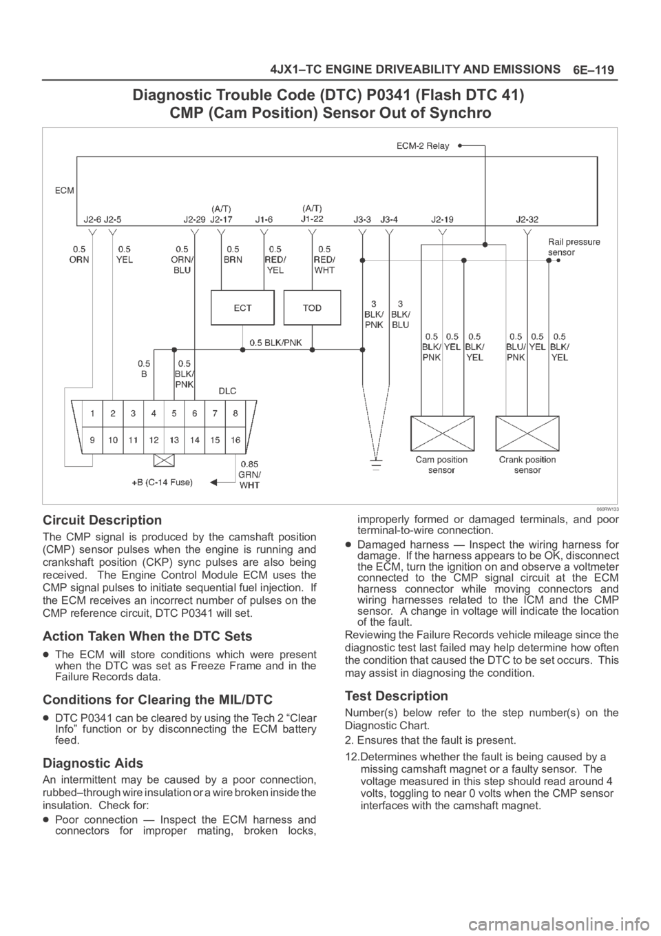
Diagnostic Trouble Code (DTC) P0341 (Flash DTC 41)
CMP (Cam Position) Sensor Out of Synchro
060RW133
Circuit Description
The CMP signal is produced by the camshaft position
(CMP) sensor pulses when the engine is running and
crankshaft position (CKP) sync pulses are also being
received. The Engine Control Module ECM uses the
CMP signal pulses to initiate sequential fuel injection. If
the ECM receives an incorrect number of pulses on the
CMP reference circuit, DTC P0341 will set.
Action Taken When the DTC Sets
The ECM will store conditions which were present
when the DTC was set as Freeze Frame and in the
Failure Records data.
Conditions for Clearing the MIL/DTC
DTC P0341 can be cleared by using the Tech 2 “Clear
Info” function or by disconnecting the ECM battery
feed.
Diagnostic Aids
An intermittent may be caused by a poor connection,
rubbed–through wire insulation or a wire broken inside the
insulation. Check for:
Poor connection — Inspect the ECM harness and
connectors for improper mating, broken locks,improperly formed or damaged terminals, and poor
terminal-to-wire connection.
Damaged harness — Inspect the wiring harness for
damage. If the harness appears to be OK, disconnect
the ECM, turn the ignition on and observe a voltmeter
connected to the CMP signal circuit at the ECM
harness connector while moving connectors and
wiring harnesses related to the ICM and the CMP
sensor. A change in voltage will indicate the location
of the fault.
Reviewing the Failure Records vehicle mileage since the
diagnostic test last failed may help determine how often
the condition that caused the DTC to be set occurs. This
may assist in diagnosing the condition.
Test Description
Number(s) below refer to the step number(s) on the
Diagnostic Chart.
2. Ensures that the fault is present.
12.Determines whether the fault is being caused by a
missing camshaft magnet or a faulty sensor. The
voltage measured in this step should read around 4
volts, toggling to near 0 volts when the CMP sensor
interfaces with the camshaft magnet.