1998 OPEL FRONTERA turn signal
[x] Cancel search: turn signalPage 2015 of 6000
6E–122
4JX1–TC ENGINE DRIVEABILITY AND EMISSIONS
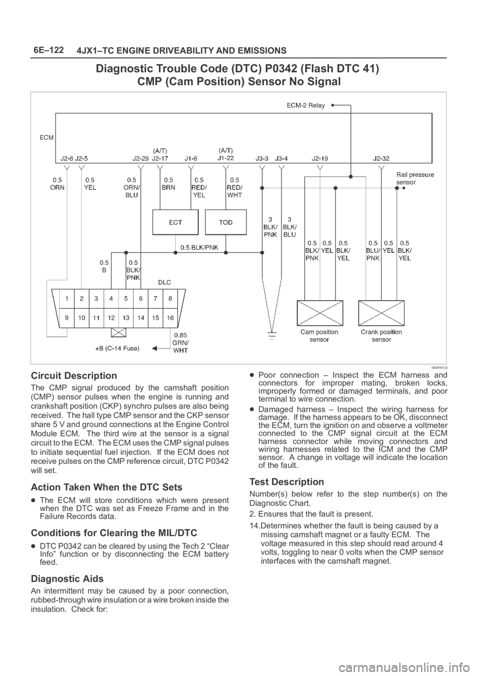
Diagnostic Trouble Code (DTC) P0342 (Flash DTC 41)
CMP (Cam Position) Sensor No Signal
060RW133
Circuit Description
The CMP signal produced by the camshaft position
(CMP) sensor pulses when the engine is running and
crankshaft position (CKP) synchro pulses are also being
received. The hall type CMP sensor and the CKP sensor
share 5 V and ground connections at the Engine Control
Module ECM. The third wire at the sensor is a signal
c i r c u i t t o t h e E C M . T h e E C M u s e s t h e C M P s i g n a l p u l s e s
to initiate sequential fuel injection. If the ECM does not
receive pulses on the CMP reference circuit, DTC P0342
will set.
Action Taken When the DTC Sets
The ECM will store conditions which were present
when the DTC was set as Freeze Frame and in the
Failure Records data.
Conditions for Clearing the MIL/DTC
DTC P0342 can be cleared by using the Tech 2 “Clear
Info” function or by disconnecting the ECM battery
feed.
Diagnostic Aids
An intermittent may be caused by a poor connection,
rubbed-through wire insulation or a wire broken inside the
insulation. Check for:
Poor connection – Inspect the ECM harness and
connectors for improper mating, broken locks,
improperly formed or damaged terminals, and poor
terminal to wire connection.
Damaged harness – Inspect the wiring harness for
damage. If the harness appears to be OK, disconnect
the ECM, turn the ignition on and observe a voltmeter
connected to the CMP signal circuit at the ECM
harness connector while moving connectors and
wiring harnesses related to the ICM and the CMP
sensor. A change in voltage will indicate the location
of the fault.
Test Description
Number(s) below refer to the step number(s) on the
Diagnostic Chart.
2. Ensures that the fault is present.
14.Determines whether the fault is being caused by a
missing camshaft magnet or a faulty ECM. The
voltage measured in this step should read around 4
volts, toggling to near 0 volts when the CMP sensor
interfaces with the camshaft magnet.
Page 2017 of 6000
6E–124
4JX1–TC ENGINE DRIVEABILITY AND EMISSIONS
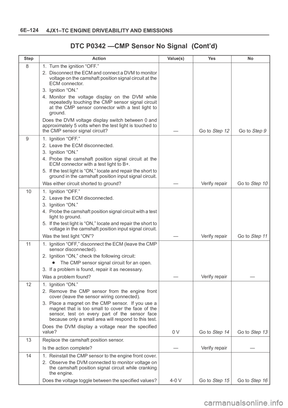
DTC P0342 —CMP Sensor No Signal
StepNo Ye s Va l u e ( s ) Action
81. Turn the ignition “OFF.”
2. Disconnect the ECM and connect a DVM to monitor
voltage on the camshaft position signal circuit at the
ECM connector.
3. Ignition “ON.”
4. Monitor the voltage display on the DVM while
repeatedly touching the CMP sensor signal circuit
at the CMP sensor connector with a test light to
ground.
Does the DVM voltage display switch between 0 and
approximately 5 volts when the test light is touched to
the CMP sensor signal circuit?
—Go to Step 12Go to Step 9
91. Ignition “OFF.”
2. Leave the ECM disconnected.
3. Ignition “ON.”
4. Probe the camshaft position signal circuit at the
ECM connector with a test light to B+.
5. If the test light is “ON,” locate and repair the short to
ground in the camshaft position input signal circuit.
Was either circuit shorted to ground?
—Verify repairGo to Step 10
101. Ignition “OFF.”
2. Leave the ECM disconnected.
3. Ignition “ON.”
4. Probe the camshaft position signal circuit with a test
light to ground.
5. If the test light is “ON,” locate and repair the short to
voltage in the camshaft position input signal circuit.
Was the test light “ON”?
—Verify repairGo to Step 11
111. Ignition “OFF,” disconnect the ECM (leave the CMP
sensor disconnected).
2. Ignition “ON,” check the following circuit:
The CMP sensor signal circuit for an open.
3. If a problem is found, repair it as necessary.
Was a problem found?
—Verify repair—
121. Ignition “ON.”
2. Remove the CMP sensor from the engine front
cover (leave the sensor wiring connected).
3. Place a magnet on the CMP sensor. If you use a
magnet that is too small to cover the face of the
sensor, test on every part of the sensor face
because only a small area will respond to this test.
Does the DVM display a voltage near the specified
value?
0 VGo to Step 14Go to Step 13
13Replace the camshaft position sensor.
Is the action complete?
—Verify repair—
141. Reinstall the CMP sensor to the engine front cover.
2. Observe the DVM connected to monitor voltage on
the camshaft position signal circuit while cranking
the engine.
Does the voltage toggle between the specified values?
4-0 VGo to Step 15Go to Step 16
Page 2024 of 6000
6E–131 4JX1–TC ENGINE DRIVEABILITY AND EMISSIONS
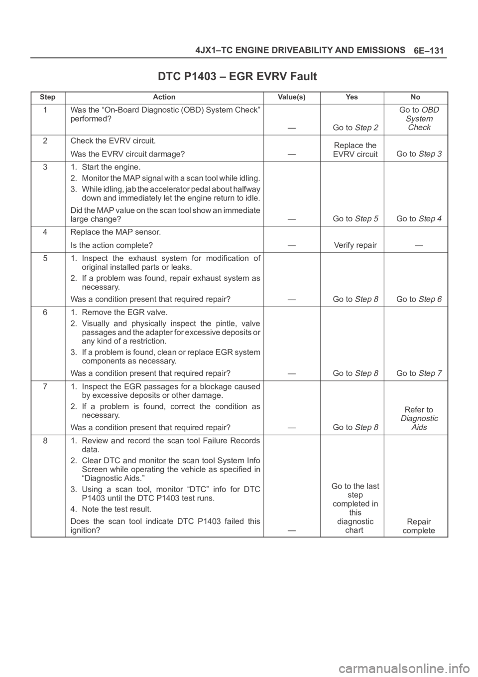
DTC P1403 – EGR EVRV Fault
StepActionVa l u e ( s )Ye sNo
1Was the “On-Board Diagnostic (OBD) System Check”
performed?
—Go to Step 2
Go to OBD
System
Check
2Check the EVRV circuit.
Was the EVRV circuit darmage?
—
Replace the
EVRV circuit
Go to Step 3
31. Start the engine.
2. Monitor the MAP signal with a scan tool while idling.
3. While idling, jab the accelerator pedal about halfway
down and immediately let the engine return to idle.
Did the MAP value on the scan tool show an immediate
large change?
—Go to Step 5Go to Step 4
4Replace the MAP sensor.
Is the action complete?
—Verify repair—
51. Inspect the exhaust system for modification of
original installed parts or leaks.
2. If a problem was found, repair exhaust system as
necessary.
Was a condition present that required repair?
—Go to Step 8Go to Step 6
61. Remove the EGR valve.
2. Visually and physically inspect the pintle, valve
passages and the adapter for excessive deposits or
any kind of a restriction.
3. If a problem is found, clean or replace EGR system
components as necessary.
Was a condition present that required repair?
—Go to Step 8Go to Step 7
71. Inspect the EGR passages for a blockage caused
by excessive deposits or other damage.
2. If a problem is found, correct the condition as
necessary.
Was a condition present that required repair?
—Go to Step 8
Refer to
Diagnostic
Aids
81. Review and record the scan tool Failure Records
data.
2. Clear DTC and monitor the scan tool System Info
Screen while operating the vehicle as specified in
“Diagnostic Aids.”
3. Using a scan tool, monitor “DTC” info for DTC
P1403 until the DTC P1403 test runs.
4. Note the test result.
Does the scan tool indicate DTC P1403 failed this
ignition?
—
Go to the last
step
completed in
this
diagnostic
chart
Repair
complete
Page 2028 of 6000
6E–135 4JX1–TC ENGINE DRIVEABILITY AND EMISSIONS
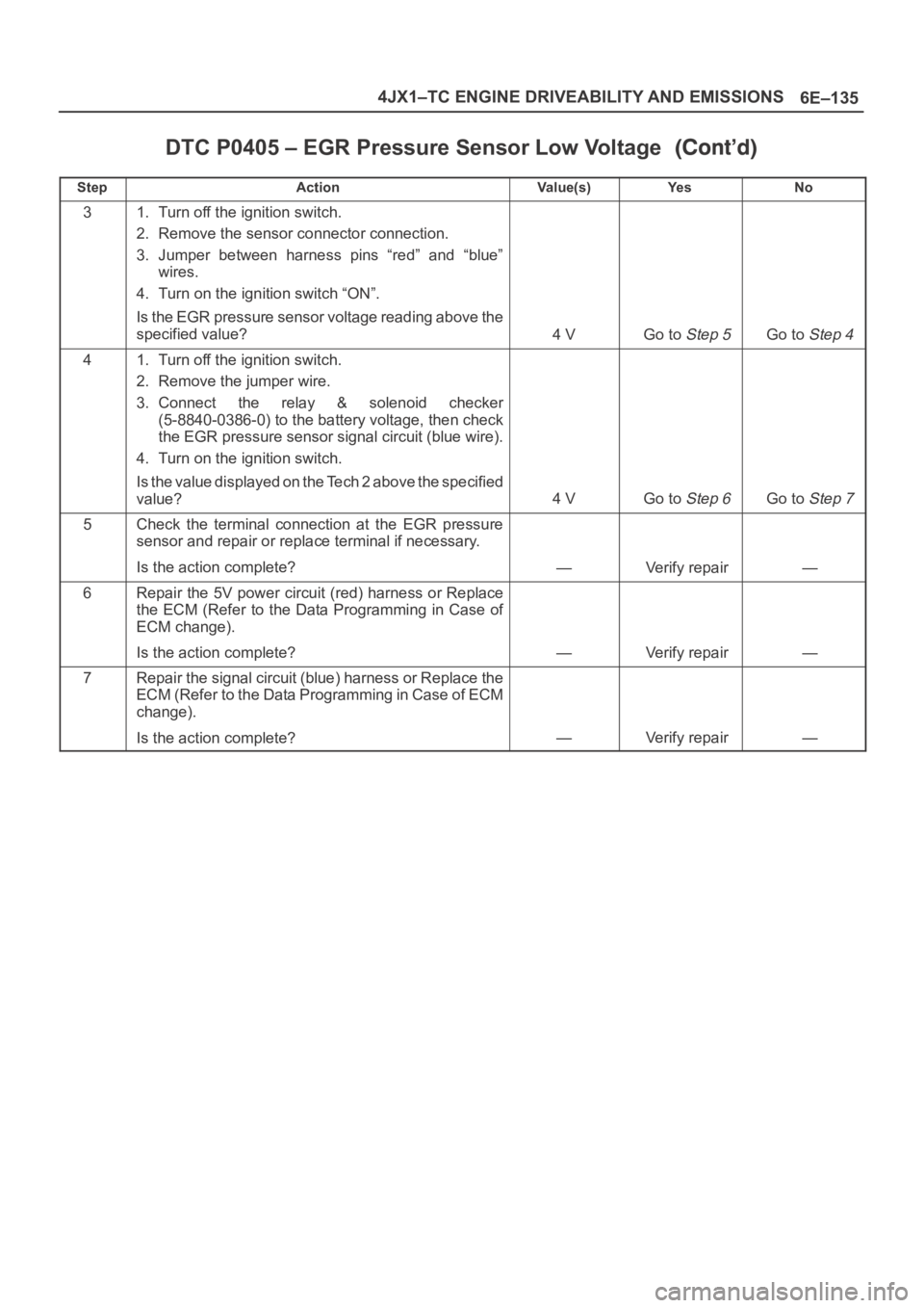
DTC P0405 – EGR Pressure Sensor Low Voltage
StepNo Ye s Va l u e ( s ) Action
31. Turn off the ignition switch.
2. Remove the sensor connector connection.
3. Jumper between harness pins “red” and “blue”
wires.
4. Turn on the ignition switch “ON”.
Is the EGR pressure sensor voltage reading above the
specified value?
4 VGo to Step 5Go to Step 4
41. Turn off the ignition switch.
2. Remove the jumper wire.
3. Connect the relay & solenoid checker
(5-8840-0386-0) to the battery voltage, then check
the EGR pressure sensor signal circuit (blue wire).
4. Turn on the ignition switch.
Is the value displayed on the Tech 2 above the specified
value?
4 VGo to Step 6Go to Step 7
5Check the terminal connection at the EGR pressure
sensor and repair or replace terminal if necessary.
Is the action complete?
—Verify repair—
6Repair the 5V power circuit (red) harness or Replace
the ECM (Refer to the Data Programming in Case of
ECM change).
Is the action complete?
—Verify repair—
7Repair the signal circuit (blue) harness or Replace the
ECM (Refer to the Data Programming in Case of ECM
change).
Is the action complete?
—Verify repair—
Page 2119 of 6000
6E–226
4JX1–TC ENGINE DRIVEABILITY AND EMISSIONS
0018
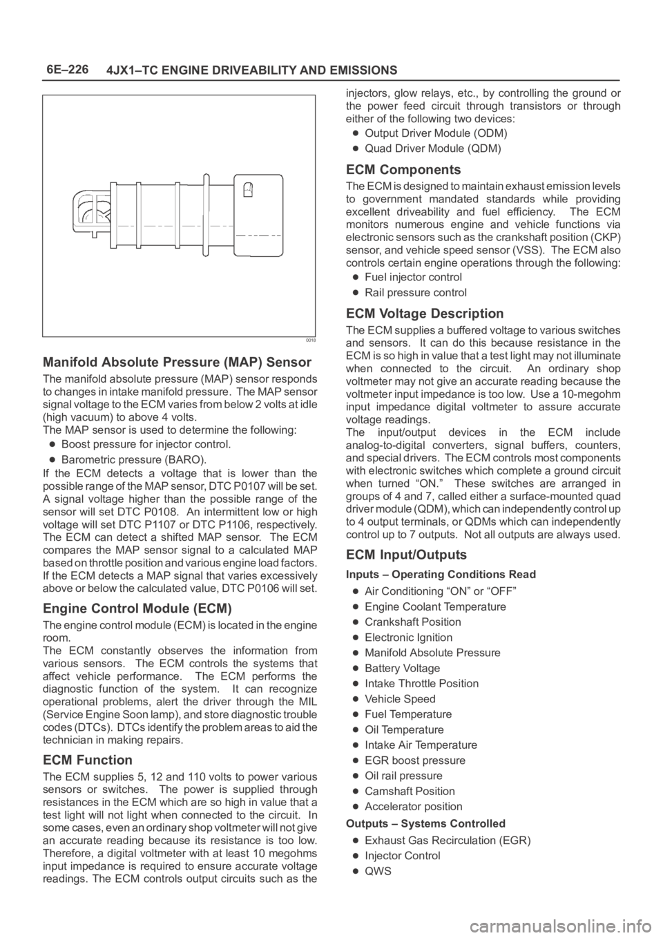
Manifold Absolute Pressure (MAP) Sensor
The manifold absolute pressure (MAP) sensor responds
to changes in intake manifold pressure. The MAP sensor
signal voltage to the ECM varies from below 2 volts at idle
(high vacuum) to above 4 volts.
The MAP sensor is used to determine the following:
Boost pressure for injector control.
Barometric pressure (BARO).
If the ECM detects a voltage that is lower than the
possible range of the MAP sensor, DTC P0107 will be set.
A signal voltage higher than the possible range of the
sensor will set DTC P0108. An intermittent low or high
voltage will set DTC P1107 or DTC P1106, respectively.
The ECM can detect a shifted MAP sensor. The ECM
compares the MAP sensor signal to a calculated MAP
based on throttle position and various engine load factors.
If the ECM detects a MAP signal that varies excessively
above or below the calculated value, DTC P0106 will set.
Engine Control Module (ECM)
The engine control module (ECM) is located in the engine
room.
The ECM constantly observes the information from
various sensors. The ECM controls the systems that
affect vehicle performance. The ECM performs the
diagnostic function of the system. It can recognize
operational problems, alert the driver through the MIL
(Service Engine Soon lamp), and store diagnostic trouble
codes (DTCs). DTCs identify the problem areas to aid the
technician in making repairs.
ECM Function
The ECM supplies 5, 12 and 110 volts to power various
sensors or switches. The power is supplied through
resistances in the ECM which are so high in value that a
test light will not light when connected to the circuit. In
some cases, even an ordinary shop voltmeter will not give
an accurate reading because its resistance is too low.
Therefore, a digital voltmeter with at least 10 megohms
input impedance is required to ensure accurate voltage
readings. The ECM controls output circuits such as theinjectors, glow relays, etc., by controlling the ground or
the power feed circuit through transistors or through
either of the following two devices:
Output Driver Module (ODM)
Quad Driver Module (QDM)
ECM Components
The ECM is designed to maintain exhaust emission levels
to government mandated standards while providing
excellent driveability and fuel efficiency. The ECM
monitors numerous engine and vehicle functions via
electronic sensors such as the crankshaft position (CKP)
sensor, and vehicle speed sensor (VSS). The ECM also
controls certain engine operations through the following:
Fuel injector control
Rail pressure control
ECM Voltage Description
The ECM supplies a buffered voltage to various switches
and sensors. It can do this because resistance in the
ECM is so high in value that a test light may not illuminate
when connected to the circuit. An ordinary shop
voltmeter may not give an accurate reading because the
voltmeter input impedance is too low. Use a 10-megohm
input impedance digital voltmeter to assure accurate
voltage readings.
The input/output devices in the ECM include
analog-to-digital converters, signal buffers, counters,
and special drivers. The ECM controls most components
with electronic switches which complete a ground circuit
when turned “ON.” These switches are arranged in
groups of 4 and 7, called either a surface-mounted quad
driver module (QDM), which can independently control up
to 4 output terminals, or QDMs which can independently
control up to 7 outputs. Not all outputs are always used.
ECM Input/Outputs
Inputs – Operating Conditions Read
Air Conditioning “ON” or “OFF”
Engine Coolant Temperature
Crankshaft Position
Electronic Ignition
Manifold Absolute Pressure
Battery Voltage
Intake Throttle Position
Vehicle Speed
Fuel Temperature
Oil Temperature
Intake Air Temperature
EGR boost pressure
Oil rail pressure
Camshaft Position
Accelerator position
Outputs – Systems Controlled
Exhaust Gas Recirculation (EGR)
Injector Control
QWS
Page 2139 of 6000

6H – 2 ENGINE SPEED CONTROL
GENERAL DESCRIPTION
2
1
101R200006
Engine control has been changed from the control
cable system to an electronically controlled TP (Throttle
Position) sensor.
The TP sensor is a potentiometer (Variable resistance)
type and installed to the accelerator pedal bracket.
A voltage of 5 V is always applied from the ECM
(Electronic Control Module) to the TP sensor so that the
operating angle of the accelerator pedal can be
detected from a change in voltage.
Further, this sensor is equipped with an accelerator
switch which sends signals to the ECM when the
accelerator pedal is stepped on.
This switch remains on and turns off only when the
accelerator pedal is stepped on.All vehicles have no throttle cable, and therefore, a
return spring is provided on the accelerator pedal and a
return cable assembly having the sliding resistance of a
cable is used to give the pedal a feeling.
To meet the newly adopted electronic control system,
the idling control button has been dropped. Legend
(1) Accerator Position Sensor
(2) Return Cable
Page 2265 of 6000
7A1–20
TRANSMISSION CONTROL SYSTEM (4L30–E)
821RW263
810RT022
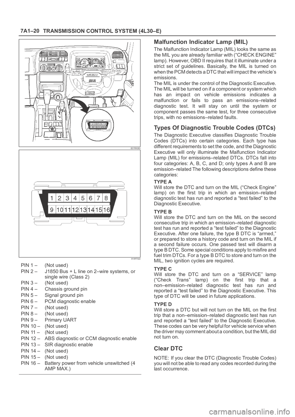
PIN 1 – (Not used)
PIN 2 – J1850 Bus + L line on 2–wire systems, or
single wire (Class 2)
PIN 3 – (Not used)
PIN 4 – Chassis ground pin
PIN 5 – Signal ground pin
PIN 6 – PCM diagnostic enable
PIN 7 – (Not used)
PIN 8 – (Not used)
PIN 9 – Primary UART
PIN 10 – (Not used)
PIN 11 – (Not used)
PIN 12 – ABS diagnostic or CCM diagnostic enable
PIN 13 – SIR diagnostic enable
PIN 14 – (Not used)
PIN 15 – (Not used)
PIN 16 – Battery power from vehicle unswitched (4
AMP MAX.)
Malfunction Indicator Lamp (MIL)
The Malfunction Indicator Lamp (MIL) looks the same as
the MIL you are already familiar with (“CHECK ENGINE”
lamp). However, OBD II requires that it illuminate under a
strict set of guidelines. Basically, the MIL is turned on
when the PCM detects a DTC that will impact the vehicle’s
emissions.
The MIL is under the control of the Diagnostic Executive.
The MIL will be turned on if a component or system which
has an impact on vehicle emissions indicates a
malfunction or fails to pass an emissions–related
diagnostic test. It will stay on until the system or
component passes the same test, for three consecutive
trips, with no emissions–related faults.
Types Of Diagnostic Trouble Codes (DTCs)
The Diagnostic Executive classifies Diagnostic Trouble
Codes (DTCs) into certain categories. Each type has
different requirements to set the code, and the Diagnostic
Executive will only illuminate the Malfunction Indicator
Lamp (MIL) for emissions–related DTCs. DTCs fall into
four categories: A, B, C, and D; only types A and B are
emission–related The following descriptions define these
categories:
TYPE A
Will store the DTC and turn on the MIL (“Check Engine”
lamp) on the first trip in which an emission–related
diagnostic test has run and reported a “test failed” to the
Diagnostic Executive.
TYPE B
Will store the DTC and turn on the MIL on the second
consecutive trip in which an emission–related diagnostic
test has run and reported a “test failed” to the Diagnostic
Executive. After one failure, the type B DTC is “armed,”
or prepared to store a history code and turn on the MIL if
a second failure occurs. One passed test will disarm a
type B DTC. Some special conditions apply to misfire and
fuel trim DTCs. For a type B DTC to store and turn on the
MIL, two ignition cycles are required.
TYPE C
Will store the DTC and turn on a “SERVICE” lamp
(“Check Trans” lamp) on the first trip that a
non–emission–related diagnostic test has run and
reported a “test failed” to the Diagnostic Executive. This
type of DTC will be used in future applications.
TYPE D
Will store a DTC but will not turn on the MIL on the first
trip that a non–emission–related diagnostic test has run
and reported a “test failed” to the Diagnostic Executive.
These codes can be very helpful for vehicle service when
the driver may comment about a condition, but the MIL did
not turn on.
Clear DTC
NOTE: If you clear the DTC (Diagnostic Trouble Codes)
you will not be able to read any codes recorded during the
last occurrence.
Page 2266 of 6000
TRANSMISSION CONTROL SYSTEM (4L30–E)7A1–21
NOTE: To use the DTC again to identify a problem, you
will need to reproduce the fault or the problem. This may
require a new test drive or just turning the ignition on (this
depends on the nature of the fault).
1. IF you have a Tech2:
1. Connect the Tech2 if it is still not connected
GOTHROUGH Tech2 OBD II CONNECTION.
2. Push “F4” and answer “Yes” to the question “Do
you really want to clear the codes?”
a. When a malfunction remains as it is the Tech2
displays “4L30E CODES NOT CLEARED”. This
means that the problem is still there or that the
recovery was not done. Please GOTO DTC
CHECK.
b. When a malfunction has been repaired and the
recovery is done. The Tech2 displays “4L30E
CODES CLEARED”.
2. IF you have no Tech2:
To clear the DTC, remove Fuse “Stop, A/T CONT”
(C–14, 15A) for at least 10 seconds.
DTC Check
1. Diagnostic Trouble Codes (DTC) have been identified
by Tech2.
2. You have written the list of the DTCs. The order of the
malfunctions has no meanings for this PCM. Usually
only one or two malfunctions should be set for a given
problem.
3. Check directly the DTCs you identified. The DTCs are
sorted by number. Refer to Diagnostic Trouble Code
(DTC) Identification in this section.
PCM Precaution
The PCM can be damaged by:
1. Electrostatic discharge
2. The short circuit of some terminals to voltage or to
ground.
Electrostatic Discharge Damage Description:
1. Electronic components used to control systems are
often designed to carry very low voltage, and are very
susceptible to damage caused by electrostatic
discharge. It is possible for less than 100 volts of
static electricity to cause damage to some electronic
components. By comparison, it takes as much as
4,000 volts for a person to even feel the zap of a static
discharge.2. There are several ways for a person to become
statically charged. The most common methods of
charging are by friction and induction. An example of
charging by friction is a person sliding across a car
seat, in which a charge of as much as 25,000 volts
can build up. Charging by induction occurs when a
person with well insulated shoes stands near a highly
charged object and momentarily touches ground.
Charges for the same polarity are drained off, leaving
the person highly charged with the opposite polarity.
Static charges of either type can cause damage,
therefore, it is important to use care when handling
and testing electronic components.
NOTICE: To prevent possible electrostatic
discharge damage:
1. Do not touch the PCM connector pins or soldered
components on the PCM circuit board.
2. Be sure to follow the guidelines listed below if
servicing any of these electronic components:
3. Do not open the replacement part package until it is
time to install the part.
4. Avoid touching electrical terminals of the part.
5. Before removing the part from its package, ground
the package to a known good ground on the vehicle.
6. Always touch a known good ground before handling
the part. This step should be repeated before
installing the part if the part has been handled while
sliding across the seat, while sitting down from a
standing position or while walking some distance.
Information On PCM
1. The Powertrain Control Module (PCM) is located in
the center console and is the control center of the
electronic transmission control system.
2. The PCM must be maintained at a temperature below
185
F (85C) at all times. This is most essential if the
vehicle is put through a paint baking process. The
PCM will become inoperative if its temperature
exceeds 85
C (185F). Therefore, it is
recommended that the PCM be removed or that
temporary insulation be placed around the PCM
during the time the vehicle is in a paint oven or other
high temperature process.
3. The PCM is designed to process the various inputs
and then respond by sending the appropriate
electrical signals to control transmission upshift,
downshift, shift feel and torque converter clutch
engagement.
4. The PCM constantly interprets information from the
various sensors, and controls the systems that affect
transmission and vehicle performance. By analyzing
operational problems, the PCM is able to perform a
diagnostic function by displaying DTC(s) and aid the
technician in making repairs.
Intermittent Conditions
If the Tech2 displays a diagnostic trouble code as
intermittent, or if after a test drive a DTC does not
reappear though the detection conditions for this DTC are
present, the problem is most likely a faulty electrical