1998 OPEL FRONTERA turn signal
[x] Cancel search: turn signalPage 1222 of 6000
6E–105 ENGINE DRIVEABILITY AND EMISSIONS
The engine oil dip stick not fully seated.
The engine oil fill cap loose or missing.
Test Description
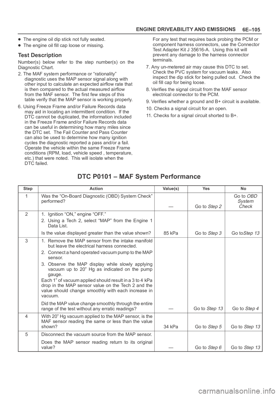
Number(s) below refer to the step number(s) on the
Diagnostic Chart.
2. The MAF system performance or “rationality”
diagnostic uses the MAP sensor signal along with
other input to calculate an expected airflow rate that
is then compared to the actual measured airflow
from the MAF sensor. The first few steps of this
table verify that the MAP sensor is working properly.
6. Using Freeze Frame and/or Failure Records data
may aid in locating an intermittent condition. If the
DTC cannot be duplicated, the information included
in the Freeze Frame and/or Failure Records data
can be useful in determining how many miles since
the DTC set. The Fail Counter and Pass Counter
can also be used to determine how many ignition
cycles the diagnostic reported a pass and/or a fail.
Operate the vehicle within the same Freeze Frame
conditions (RPM, load, vehicle speed , temperature,
etc.) that were noted. This will isolate when the
DTC failed.For any test that requires back probing the PCM or
component harness connectors, use the Connector
Test Adapter Kit J 35616-A. Using this kit will
prevent any damage to the harness connector
terminals.
7. Any un-metered air may cause this DTC to set.
Check the PVC system for vacuum leaks. Also
inspect the dip stick for being pulled out. Check the
oil fill cap for being loose.
8. Verifies the signal circuit from the MAF sensor
electrical connector to the PCM.
9. Verifies whether a ground and B+ circuit is available.
10. Checks a signal circuit for an open.
11. Checks for a signal circuit shorted to B+.
DTC P0101 – MAF System Performance
StepActionVa l u e ( s )Ye sNo
1Was the “On-Board Diagnostic (OBD) System Check”
performed?
—Go to Step 2
Go to OBD
System
Check
21. Ignition “ON,” engine “OFF.”
2. Using a Tech 2, select “MAP” from the Engine 1
Data List.
Is the value displayed greater than the value shown?
85 kPaGo to Step 3Go toStep 13
31. Remove the MAP sensor from the intake manifold
but leave the electrical harness connected.
2. Connect a hand operated vacuum pump to the MAP
sensor.
3. Observe the MAP display while slowly applying
vacuum up to 20” Hg as indicated on the pump
gauge.
Each 1” of vacuum applied should result in a 3 to 4 kPa
drop in the MAP sensor value on the Tech 2 and the
value should change smoothly with each increase in
vacuum.
Did the MAP value change smoothly through the entire
range of the test without any erratic readings?
—Go to Step 13Go to Step 4
4With 20” Hg vacuum applied to the MAP sensor, is the
MAF sensor reading the same or less than the value
shown?
34 kPaGo to Step 5Go to Step 13
5Disconnect the vacuum source from the MAP sensor.
Does the MAP sensor reading return to its original
value?
—Go to Step 6Go to Step 13
Page 1257 of 6000
6E–140
ENGINE DRIVEABILITY AND EMISSIONS
HO2S, causing the system to appear lean. Check for
exhaust leaks that may cause a false lean condition to
be indicated.
MAF sensor – The system can go lean if the MAF
sensor signal indicates an engine airfiow
measurement that is not correct. Disconnect the MAF
sensor to see if the lean condition is corrected. If so,
replace the MAF sensor.
Fuel contamination – Water, even in small amounts,
can be delivered to the fuel injectors. The water can
cause a lean exhaust to be indicated. Excessive
alcohol in the fuel can also cause this condition. Refer
to
Fuel System Diagnosis for the procedure to check
for fuel contamination.
If none of the above conditions are present, replace the
affected HO2S.
Test Description
Number(s) below refer to step numbers on the diagnostic
chart.
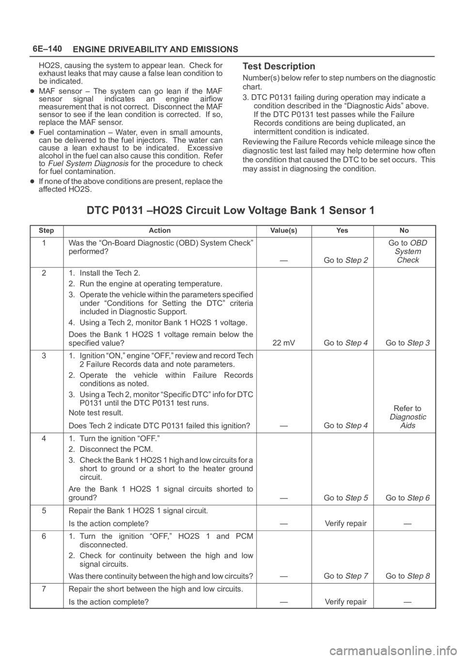
3. DTC P0131 failing during operation may indicate a
condition described in the “Diagnostic Aids” above.
If the DTC P0131 test passes while the Failure
Records conditions are being duplicated, an
intermittent condition is indicated.
Reviewing the Failure Records vehicle mileage since the
diagnostic test last failed may help determine how often
the condition that caused the DTC to be set occurs. This
may assist in diagnosing the condition.
DTC P0131 –HO2S Circuit Low Voltage Bank 1 Sensor 1
StepActionVa l u e ( s )Ye sNo
1Was the “On-Board Diagnostic (OBD) System Check”
performed?
—Go to Step 2
Go to OBD
System
Check
21. Install the Tech 2.
2. Run the engine at operating temperature.
3. Operate the vehicle within the parameters specified
under “Conditions for Setting the DTC” criteria
included in Diagnostic Support.
4. Using a Tech 2, monitor Bank 1 HO2S 1 voltage.
Does the Bank 1 HO2S 1 voltage remain below the
specified value?
22 mVGo to Step 4Go to Step 3
31. Ignition “ON,” engine “OFF,” review and record Tech
2 Failure Records data and note parameters.
2. Operate the vehicle within Failure Records
conditions as noted.
3. Using a Tech 2, monitor “Specific DTC” info for DTC
P0131 until the DTC P0131 test runs.
Note test result.
Does Tech 2 indicate DTC P0131 failed this ignition?
—Go to Step 4
Refer to
Diagnostic
Aids
41. Turn the ignition “OFF.”
2. Disconnect the PCM.
3. Check the Bank 1 HO2S 1 high and low circuits for a
short to ground or a short to the heater ground
circuit.
Are the Bank 1 HO2S 1 signal circuits shorted to
ground?
—Go to Step 5Go to Step 6
5Repair the Bank 1 HO2S 1 signal circuit.
Is the action complete?
—Verify repair—
61. Turn the ignition “OFF,” HO2S 1 and PCM
disconnected.
2. Check for continuity between the high and low
signal circuits.
Was there continuity between the high and low circuits?
—Go to Step 7Go to Step 8
7Repair the short between the high and low circuits.
Is the action complete?
—Verify repair—
Page 1263 of 6000
6E–146
ENGINE DRIVEABILITY AND EMISSIONS
indicates a signal line shorted to ground or signal lines
shorted together. Disconnect the HO2S and connect
a test light between the HO2S ignition feed and heater
ground circuits. If the test light does not light for 2
seconds when the ignition is turned on, repair the open
ignition feed or sensor ground circuit as necessary. If
the test light lights and the HO2S signal and low circuits
are OK, replace the HO2S.
Intermittent test – With the Ignition “ON,” monitor the
HO2S signal voltage while moving the wiring harness
and related connectors. If the fault is induced, the
HO2S signal voltage will change. This may help isolate
the location of the malfunction.
Test Description
Number(s) below refer to the step number(s) on the
Diagnostic Chart.
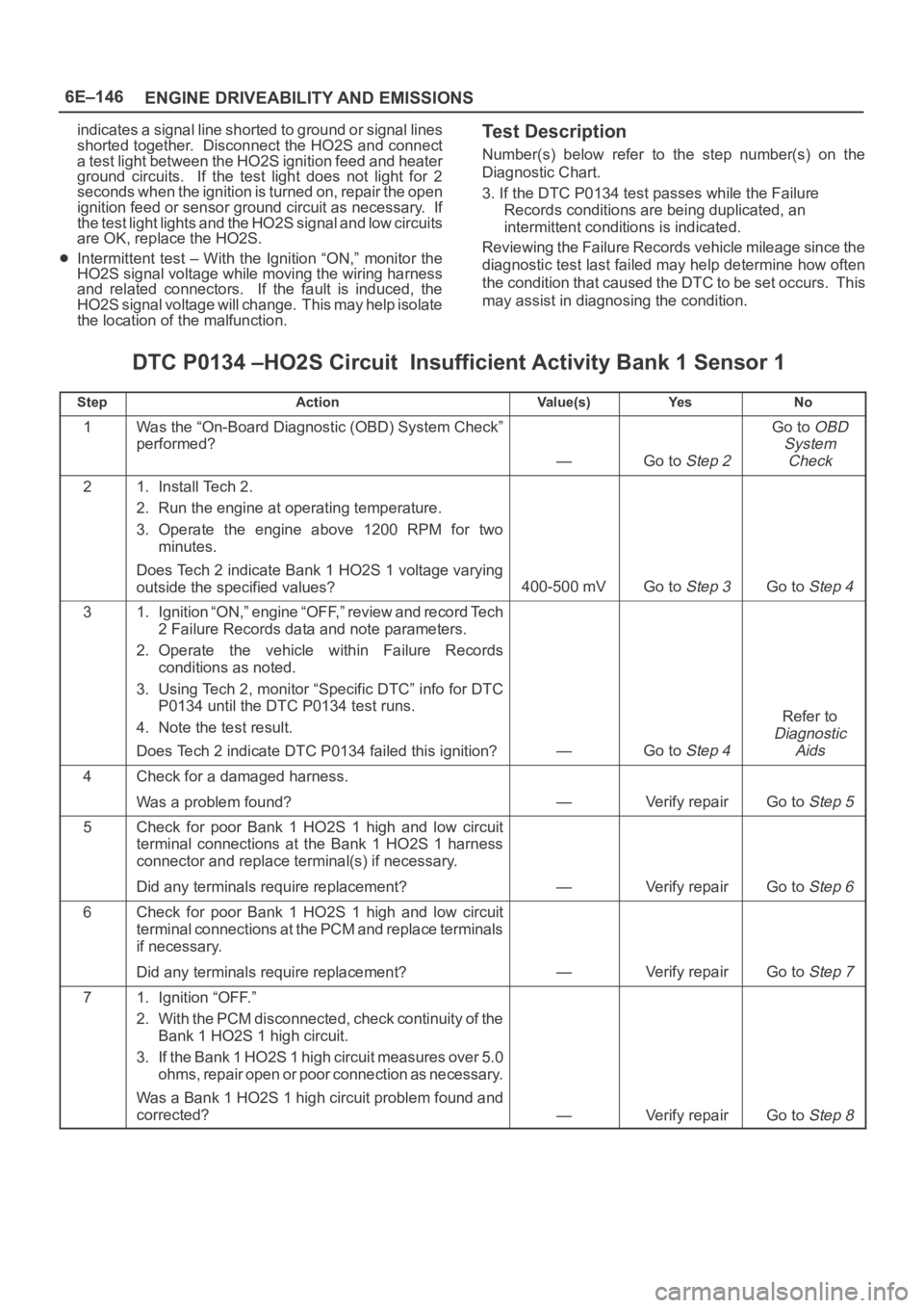
3. If the DTC P0134 test passes while the Failure
Records conditions are being duplicated, an
intermittent conditions is indicated.
Reviewing the Failure Records vehicle mileage since the
diagnostic test last failed may help determine how often
the condition that caused the DTC to be set occurs. This
may assist in diagnosing the condition.
DTC P0134 –HO2S Circuit Insufficient Activity Bank 1 Sensor 1
StepActionVa l u e ( s )Ye sNo
1Was the “On-Board Diagnostic (OBD) System Check”
performed?
—Go to Step 2
Go to OBD
System
Check
21. Install Tech 2.
2. Run the engine at operating temperature.
3. Operate the engine above 1200 RPM for two
minutes.
Does Tech 2 indicate Bank 1 HO2S 1 voltage varying
outside the specified values?
400-500 mVGo to Step 3Go to Step 4
31. Ignition “ON,” engine “OFF,” review and record Tech
2 Failure Records data and note parameters.
2. Operate the vehicle within Failure Records
conditions as noted.
3. Using Tech 2, monitor “Specific DTC” info for DTC
P0134 until the DTC P0134 test runs.
4. Note the test result.
Does Tech 2 indicate DTC P0134 failed this ignition?
—Go to Step 4
Refer to
Diagnostic
Aids
4Check for a damaged harness.
Was a problem found?
—Verify repairGo to Step 5
5Check for poor Bank 1 HO2S 1 high and low circuit
terminal connections at the Bank 1 HO2S 1 harness
connector and replace terminal(s) if necessary.
Did any terminals require replacement?
—Verify repairGo to Step 6
6Check for poor Bank 1 HO2S 1 high and low circuit
terminal connections at the PCM and replace terminals
if necessary.
Did any terminals require replacement?
—Verify repairGo to Step 7
71. Ignition “OFF.”
2. With the PCM disconnected, check continuity of the
Bank 1 HO2S 1 high circuit.
3. If the Bank 1 HO2S 1 high circuit measures over 5.0
ohms, repair open or poor connection as necessary.
Was a Bank 1 HO2S 1 high circuit problem found and
corrected?
—Verify repairGo to Step 8
Page 1266 of 6000
6E–149 ENGINE DRIVEABILITY AND EMISSIONS
exhaust leaks that may cause a false lean condition to
be indicated.
MAF sensor –The system can go lean if the MAF
sensor signal indicates an engine airflow
measurement that is not correct. Disconnect the MAF
sensor to see if the lean condition is corrected. If so,
replace the MAF sensor.
Fuel contamination – Water, even in small amounts,
can be delivered to the fuel injectors. The water can
cause a lean exhaust to be indicated. Excessive
alcohol in the fuel can also cause this condition. Refer
to
Fuel System Diagnosis for the procedure to check
for fuel contamination.
If none of the above conditions are present, replace the
affected HO2S.
Test Description
Number(s) below refer to the step number(s) on the
Diagnostic Chart.
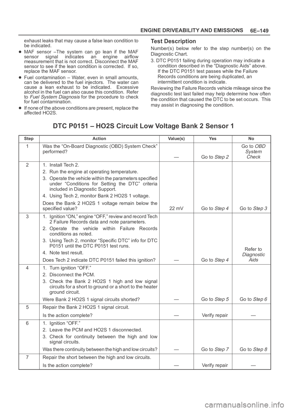
3. DTC P0151 failing during operation may indicate a
condition described in the “Diagnostic Aids” above.
If the DTC P0151 test passes while the Failure
Records conditions are being duplicated, an
intermittent condition is indicate.
Reviewing the Failure Records vehicle mileage since the
diagnostic test last failed may help determine how often
the condition that caused the DTC to be set occurs. This
may assist in diagnosing the condition.
DTC P0151 – HO2S Circuit Low Voltage Bank 2 Sensor 1
StepActionVa l u e ( s )Ye sNo
1Was the “On-Board Diagnostic (OBD) System Check”
performed?
—Go to Step 2
Go to OBD
System
Check
21. Install Tech 2.
2. Run the engine at operating temperature.
3. Operate the vehicle within the parameters specified
under “Conditions for Setting the DTC” criteria
included in Diagnostic Support.
4. Using Tech 2, monitor Bank 2 HO2S 1 voltage.
Does the Bank 2 HO2S 1 voltage remain below the
specified value?
22 mVGo to Step 4Go to Step 3
31. Ignition “ON,” engine “OFF,” review and record Tech
2 Failure Records data and note parameters.
2. Operate the vehicle within Failure Records
conditions as noted.
3. Using Tech 2, monitor “Specific DTC” info for DTC
P0151 until the DTC P0151 test runs.
4. Note test result.
Does Tech 2 indicate DTC P0151 failed this ignition?
—Go to Step 4
Refer to
Diagnostic
Aids
41. Turn ignition “OFF.”
2. Disconnect the PCM.
3. Check the Bank 2 HO2S 1 high and low signal
circuits for a short to ground or a short to the heater
ground circuit.
Were Bank 2 HO2S 1 signal circuits shorted?
—Go to Step 5Go to Step 6
5Repair the Bank 2 HO2S 1 signal circuit.
Is the action complete?
—Verify repair—
61. Ignition “OFF.”
2. Leave the PCM and HO2S 1 disconnected.
3. Check for continuity between the high and low
signal circuits.
Was there continuity between the high and low circuits?
—Go to Step 7Go to Step 8
7Repair the short between the high and low circuits.
Is the action complete?
—Verify repair—
Page 1287 of 6000
6E–170
ENGINE DRIVEABILITY AND EMISSIONS
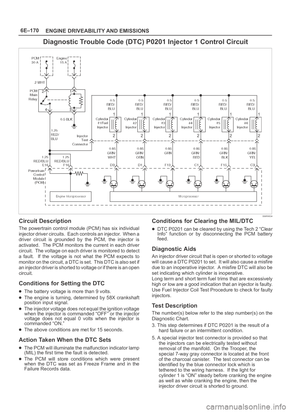
Diagnostic Trouble Code (DTC) P0201 Injector 1 Control Circuit
D06RW034
Circuit Description
The powertrain control module (PCM) has six individual
injector driver circuits. Each controls an injector. When a
driver circuit is grounded by the PCM, the injector is
activated. The PCM monitors the current in each driver
circuit. The voltage on each driver is monitored to detect
a fault. If the voltage is not what the PCM expects to
m o n i t o r o n t h e c i r c u i t , a D T C i s s e t . T h i s D T C i s a l s o s e t i f
an injector driver is shorted to voltage or if there is an open
circuit.
Conditions for Setting the DTC
The battery voltage is more than 9 volts.
The engine is turning, determined by 58X crankshaft
position input signal.
The injector voltage does not equal the ignition voltage
when the injector is commanded “OFF” or the injector
voltage does not equal 0 volts when the injector is
commanded “ON.”
The above conditions are met for 15 seconds.
Action Taken When the DTC Sets
The PCM will illuminate the malfunction indicator lamp
(MIL) the first time the fault is detected.
The PCM will store conditions which were present
when the DTC was set as Freeze Frame and in the
Failure Records data.
Conditions for Clearing the MIL/DTC
DTC P0201 can be cleared by using the Tech 2 “Clear
Info” function or by disconnecting the PCM battery
feed.
Diagnostic Aids
An injector driver circuit that is open or shorted to voltage
will cause a DTC P0201 to set. It will also cause a misfire
due to an inoperative injector. A misfire DTC will also be
set indicating which cylinder is inoperative.
Long term and short term fuel trims that are excessively
high or low are a good indication that an injector is faulty.
Use Fuel Injector Coil Test Procedure to check for faulty
injectors.
Test Description
The number(s) below refer to the step number(s) on the
Diagnostic Chart.
3. This step determines if DTC P0201 is the result of a
hard failure or an intermittent condition.
5. A special injector test connector is provided so that
the injectors can be electrically tested without
removal of the manifold. On the Trooper, the
special 7-way gray connector is located at the front
of the charcoal canister. The test connector can be
identified by the blue connector lock which is
tethered to the wiring harness. If the light for
cylinder 1 is “ON” steady before cranking the engine
as well as while cranking the engine, then the
injector driver circuit is shorted to ground.
Page 1290 of 6000
6E–173 ENGINE DRIVEABILITY AND EMISSIONS
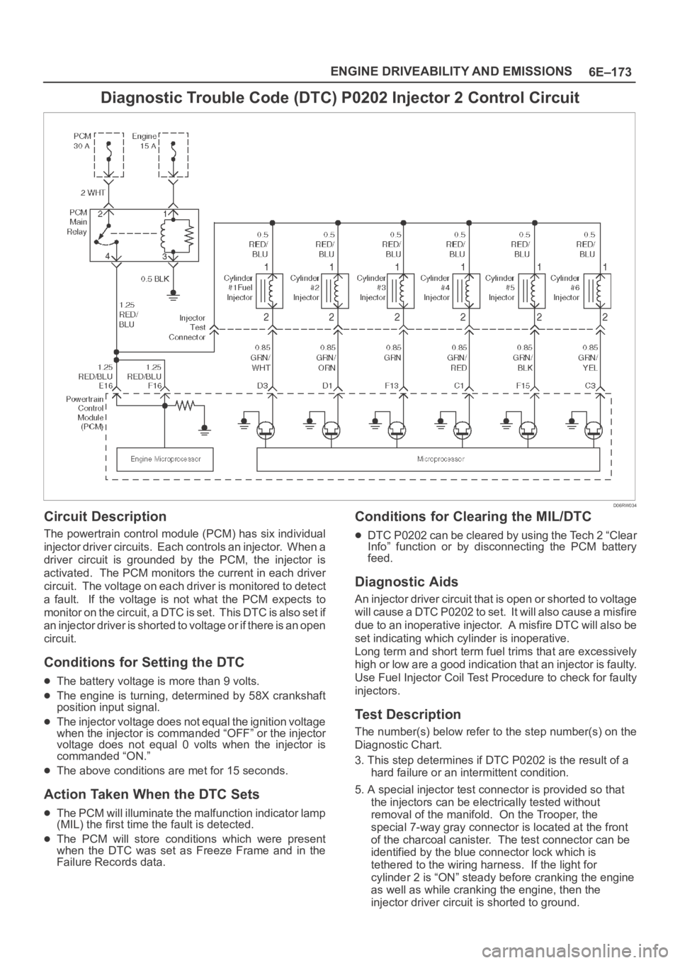
Diagnostic Trouble Code (DTC) P0202 Injector 2 Control Circuit
D06RW034
Circuit Description
The powertrain control module (PCM) has six individual
injector driver circuits. Each controls an injector. When a
driver circuit is grounded by the PCM, the injector is
activated. The PCM monitors the current in each driver
circuit. The voltage on each driver is monitored to detect
a fault. If the voltage is not what the PCM expects to
m o n i t o r o n t h e c i r c u i t , a D T C i s s e t . T h i s D T C i s a l s o s e t i f
an injector driver is shorted to voltage or if there is an open
circuit.
Conditions for Setting the DTC
The battery voltage is more than 9 volts.
The engine is turning, determined by 58X crankshaft
position input signal.
The injector voltage does not equal the ignition voltage
when the injector is commanded “OFF” or the injector
voltage does not equal 0 volts when the injector is
commanded “ON.”
The above conditions are met for 15 seconds.
Action Taken When the DTC Sets
The PCM will illuminate the malfunction indicator lamp
(MIL) the first time the fault is detected.
The PCM will store conditions which were present
when the DTC was set as Freeze Frame and in the
Failure Records data.
Conditions for Clearing the MIL/DTC
DTC P0202 can be cleared by using the Tech 2 “Clear
Info” function or by disconnecting the PCM battery
feed.
Diagnostic Aids
An injector driver circuit that is open or shorted to voltage
will cause a DTC P0202 to set. It will also cause a misfire
due to an inoperative injector. A misfire DTC will also be
set indicating which cylinder is inoperative.
Long term and short term fuel trims that are excessively
high or low are a good indication that an injector is faulty.
Use Fuel Injector Coil Test Procedure to check for faulty
injectors.
Test Description
The number(s) below refer to the step number(s) on the
Diagnostic Chart.
3. This step determines if DTC P0202 is the result of a
hard failure or an intermittent condition.
5. A special injector test connector is provided so that
the injectors can be electrically tested without
removal of the manifold. On the Trooper, the
special 7-way gray connector is located at the front
of the charcoal canister. The test connector can be
identified by the blue connector lock which is
tethered to the wiring harness. If the light for
cylinder 2 is “ON” steady before cranking the engine
as well as while cranking the engine, then the
injector driver circuit is shorted to ground.
Page 1293 of 6000
6E–176
ENGINE DRIVEABILITY AND EMISSIONS
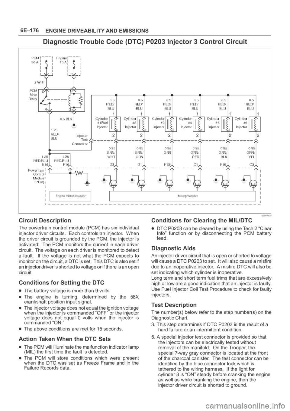
Diagnostic Trouble Code (DTC) P0203 Injector 3 Control Circuit
D06RW034
Circuit Description
The powertrain control module (PCM) has six individual
injector driver circuits. Each controls an injector. When
the driver circuit is grounded by the PCM, the injector is
activated. The PCM monitors the current in each driver
circuit. The voltage on each driver is monitored to detect
a fault. If the voltage is not what the PCM expects to
m o n i t o r o n t h e c i r c u i t , a D T C i s s e t . T h i s D T C i s a l s o s e t i f
an injector driver is shorted to voltage or if there is an open
circuit.
Conditions for Setting the DTC
The battery voltage is more than 9 volts.
The engine is turning, determined by the 58X
crankshaft position input signal.
The injector voltage does not equal the ignition voltage
when the injector is commanded “OFF” or the injector
voltage does not equal 0 volts when the injector is
commanded “ON.”
The above conditions are met for 15 seconds.
Action Taken When the DTC Sets
The PCM will illuminate the malfunction indicator lamp
(MIL) the first time the fault is detected.
The PCM will store conditions which were present
when the DTC was set as Freeze Frame and in the
Failure Records data.
Conditions for Clearing the MIL/DTC
DTC P0203 can be cleared by using the Tech 2 “Clear
Info” function or by disconnecting the PCM battery
feed.
Diagnostic Aids
An injector driver circuit that is open or shorted to voltage
will cause a DTC P0203 to set. It will also cause a misfire
due to an inoperative injector. A misfire DTC will also be
set indicating which cylinder is inoperative.
Long term and short term fuel trims that are excessively
high or low are a good indication that an injector is faulty.
Use Fuel Injector Coil Test Procedure to check for faulty
injectors.
Test Description
The number(s) below refer to the step number(s) on the
Diagnostic Chart.
3. This step determines if DTC P0203 is the result of a
hard failure or an intermittent condition.
5. A special injector test connector is provided so that
the injectors can be electrically tested without
removal of the manifold. On the Trooper, the
special 7-way gray connector is located at the front
of the charcoal canister. The test connector can be
identified by the blue connector lock which is
tethered to the wiring harness. If the light for
cylinder 3 is “ON” steady before cranking the engine
as well as while cranking the engine, then the
injector driver circuit is shorted to ground.
Page 1296 of 6000
6E–179 ENGINE DRIVEABILITY AND EMISSIONS
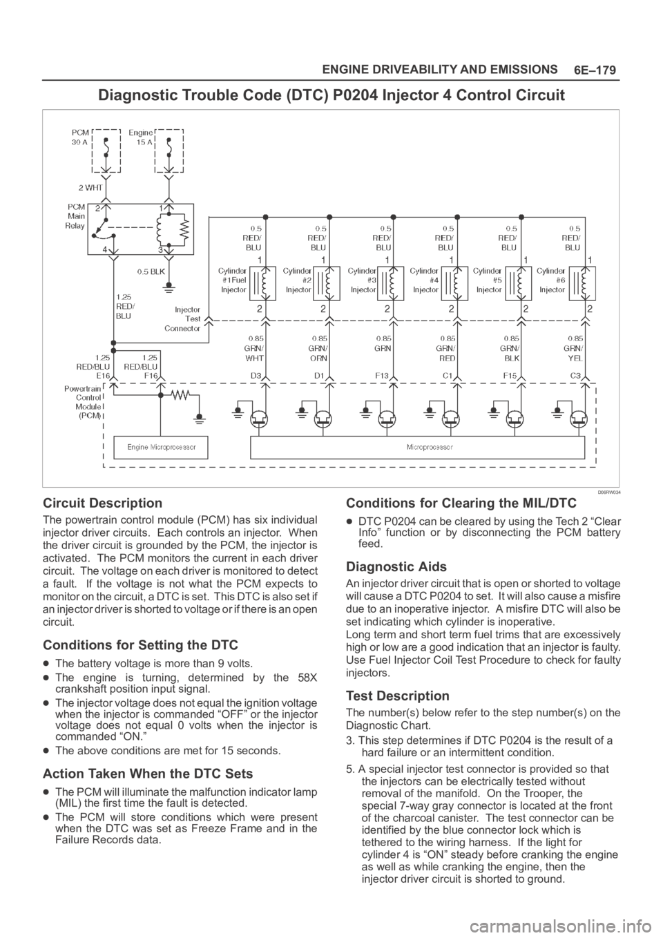
Diagnostic Trouble Code (DTC) P0204 Injector 4 Control Circuit
D06RW034
Circuit Description
The powertrain control module (PCM) has six individual
injector driver circuits. Each controls an injector. When
the driver circuit is grounded by the PCM, the injector is
activated. The PCM monitors the current in each driver
circuit. The voltage on each driver is monitored to detect
a fault. If the voltage is not what the PCM expects to
m o n i t o r o n t h e c i r c u i t , a D T C i s s e t . T h i s D T C i s a l s o s e t i f
an injector driver is shorted to voltage or if there is an open
circuit.
Conditions for Setting the DTC
The battery voltage is more than 9 volts.
The engine is turning, determined by the 58X
crankshaft position input signal.
The injector voltage does not equal the ignition voltage
when the injector is commanded “OFF” or the injector
voltage does not equal 0 volts when the injector is
commanded “ON.”
The above conditions are met for 15 seconds.
Action Taken When the DTC Sets
The PCM will illuminate the malfunction indicator lamp
(MIL) the first time the fault is detected.
The PCM will store conditions which were present
when the DTC was set as Freeze Frame and in the
Failure Records data.
Conditions for Clearing the MIL/DTC
DTC P0204 can be cleared by using the Tech 2 “Clear
Info” function or by disconnecting the PCM battery
feed.
Diagnostic Aids
An injector driver circuit that is open or shorted to voltage
will cause a DTC P0204 to set. It will also cause a misfire
due to an inoperative injector. A misfire DTC will also be
set indicating which cylinder is inoperative.
Long term and short term fuel trims that are excessively
high or low are a good indication that an injector is faulty.
Use Fuel Injector Coil Test Procedure to check for faulty
injectors.
Test Description
The number(s) below refer to the step number(s) on the
Diagnostic Chart.
3. This step determines if DTC P0204 is the result of a
hard failure or an intermittent condition.
5. A special injector test connector is provided so that
the injectors can be electrically tested without
removal of the manifold. On the Trooper, the
special 7-way gray connector is located at the front
of the charcoal canister. The test connector can be
identified by the blue connector lock which is
tethered to the wiring harness. If the light for
cylinder 4 is “ON” steady before cranking the engine
as well as while cranking the engine, then the
injector driver circuit is shorted to ground.