1998 OPEL FRONTERA turn signal
[x] Cancel search: turn signalPage 866 of 6000
5A–56
BRAKE CONTROL SYSTEM
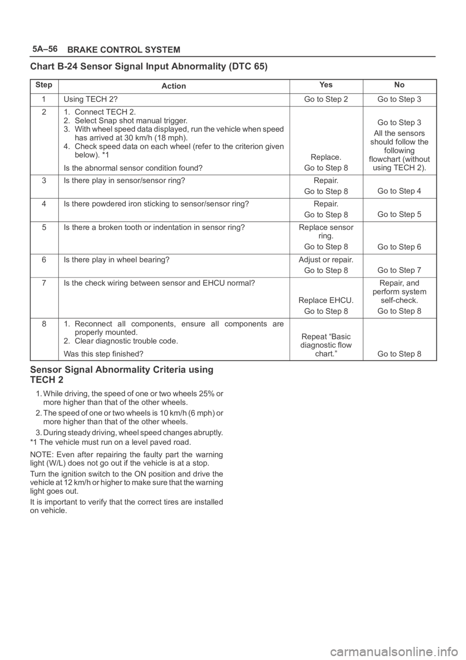
Chart B-24 Sensor Signal Input Abnormality (DTC 65)
StepActionYe sNo
1Using TECH 2?Go to Step 2Go to Step 3
21. Connect TECH 2.
2. Select Snap shot manual trigger.
3. With wheel speed data displayed, run the vehicle when speed
has arrived at 30 km/h (18 mph).
4. Check speed data on each wheel (refer to the criterion given
below). *1
Is the abnormal sensor condition found?
Replace.
Go to Step 8
Go to Step 3
All the sensors
should follow the
following
flowchart (without
using TECH 2).
3Is there play in sensor/sensor ring?Repair.
Go to Step 8
Go to Step 4
4Is there powdered iron sticking to sensor/sensor ring?Repair.
Go to Step 8
Go to Step 5
5Is there a broken tooth or indentation in sensor ring?Replace sensor
ring.
Go to Step 8
Go to Step 6
6Is there play in wheel bearing?Adjust or repair.
Go to Step 8
Go to Step 7
7Is the check wiring between sensor and EHCU normal?
Replace EHCU.
Go to Step 8
Repair, and
perform system
self-check.
Go to Step 8
81. Reconnect all components, ensure all components are
properly mounted.
2. Clear diagnostic trouble code.
Was this step finished?
Repeat “Basic
diagnostic flow
chart.”
Go to Step 8
Sensor Signal Abnormality Criteria using
TECH 2
1. While driving, the speed of one or two wheels 25% or
more higher than that of the other wheels.
2. The speed of one or two wheels is 10 km/h (6 mph) or
more higher than that of the other wheels.
3. During steady driving, wheel speed changes abruptly.
*1 The vehicle must run on a level paved road.
NOTE: Even after repairing the faulty part the warning
light (W/L) does not go out if the vehicle is at a stop.
Turn the ignition switch to the ON position and drive the
vehicle at 12 km/h or higher to make sure that the warning
light goes out.
It is important to verify that the correct tires are installed
on vehicle.
Page 1070 of 6000

6C–3
ENGINE FUEL
Adhere to all Notices and Cautions.
All gasoline engines are designed to use only unleaded
gasoline. Unleaded gasoline must be used for proper
emission control system operation.
Its use will also minimize spark plug fouling and extend
engine oil life. Using leaded gasoline can damage the
emission control system and could result in loss of
emission warranty coverage.
All cars are equipped with an Evaporative Emission
Control System. The purpose of the system is to minimize
the escape of fuel vapors to the atmosphere.
Fuel Metering
The Engine Control Module (ECM) is in complete control
of this fuel delivery system during normal driving
conditions.
The intake manifold function, like that of a diesel, is used
only to let air into the engine. The fuel is injected by
separate injectors that are mounted over the intake
manifold.
The Manifold Absolute Pressure (MAP) sensor measures
the changes in the intake manifold pressure which result
from engine load and speed changes, which the MAP
sensor converts to a voltage output.
This sensor generates the voltage to change
corresponding to the flow of the air drawn into the engine.
The changing voltage is transformed into an electric
signal and provided to the ECM.
With receipt of the signals sent from the MAP sensor,
Intake Air Temperature sensor and others, the ECM
determines an appropriate fuel injection pulse width
feeding such information to the fuel injector valves to
effect an appropriate air/fuel ratio.
The Multiport Fuel Injection system utilizes an injection
system where the injectors turn on at every crankshaft
re vol u tion . Th e EC M con tro ls t he in je cto r on tim e so t ha t
the correct amount of fuel is metered depending on
driving conditions.
Two interchangeable “O” rings are used on the injector
that must be replaced when the injectors are removed.
The fuel rail is attached to the top of the intake manifold
and supplies fuel to all the injectors.
Fuel is recirculated through the rail continually while the
engine is running. This removes air and vapors from the
fuel as well as keeping the fuel cool during hot weather
operation.
The fuel pressure control valve that is mounted on the fuel
rail maintains a pressure differential across the injectors
under all operating conditions. It is accomplished by
controlling the amount of fuel that is recirculated back to
the fuel tank based on engine demand.
See Section “Driveability and Emission” for more
information and diagnosis.
Page 1087 of 6000
6D2–2
IGNITION SYSTEM
General Description
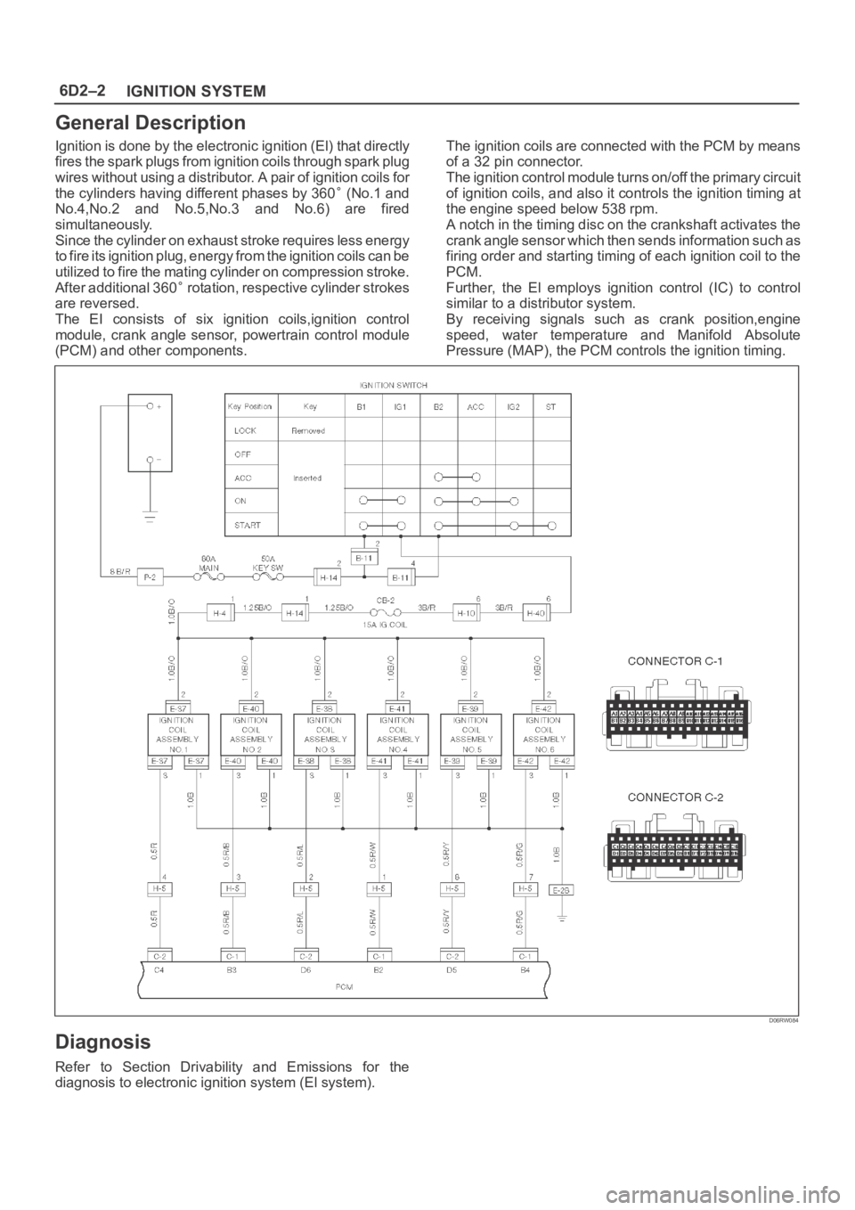
Ignition is done by the electronic ignition (El) that directly
fires the spark plugs from ignition coils through spark plug
wires without using a distributor. A pair of ignition coils for
the cylinders having different phases by 360
(No.1 and
No.4,No.2 and No.5,No.3 and No.6) are fired
simultaneously.
Since the cylinder on exhaust stroke requires less energy
to fire its ignition plug, energy from the ignition coils can be
utilized to fire the mating cylinder on compression stroke.
After additional 360
rotation, respective cylinder strokes
are reversed.
The EI consists of six ignition coils,ignition control
module, crank angle sensor, powertrain control module
(PCM) and other components.The ignition coils are connected with the PCM by means
of a 32 pin connector.
The ignition control module turns on/off the primary circuit
of ignition coils, and also it controls the ignition timing at
the engine speed below 538 rpm.
A notch in the timing disc on the crankshaft activates the
crank angle sensor which then sends information such as
firing order and starting timing of each ignition coil to the
PCM.
Further, the El employs ignition control (IC) to control
similar to a distributor system.
By receiving signals such as crank position,engine
speed, water temperature and Manifold Absolute
Pressure (MAP), the PCM controls the ignition timing.
D06RW084
Diagnosis
Refer to Section Drivability and Emissions for the
diagnosis to electronic ignition system (El system).
Page 1139 of 6000
6E–22
ENGINE DRIVEABILITY AND EMISSIONS
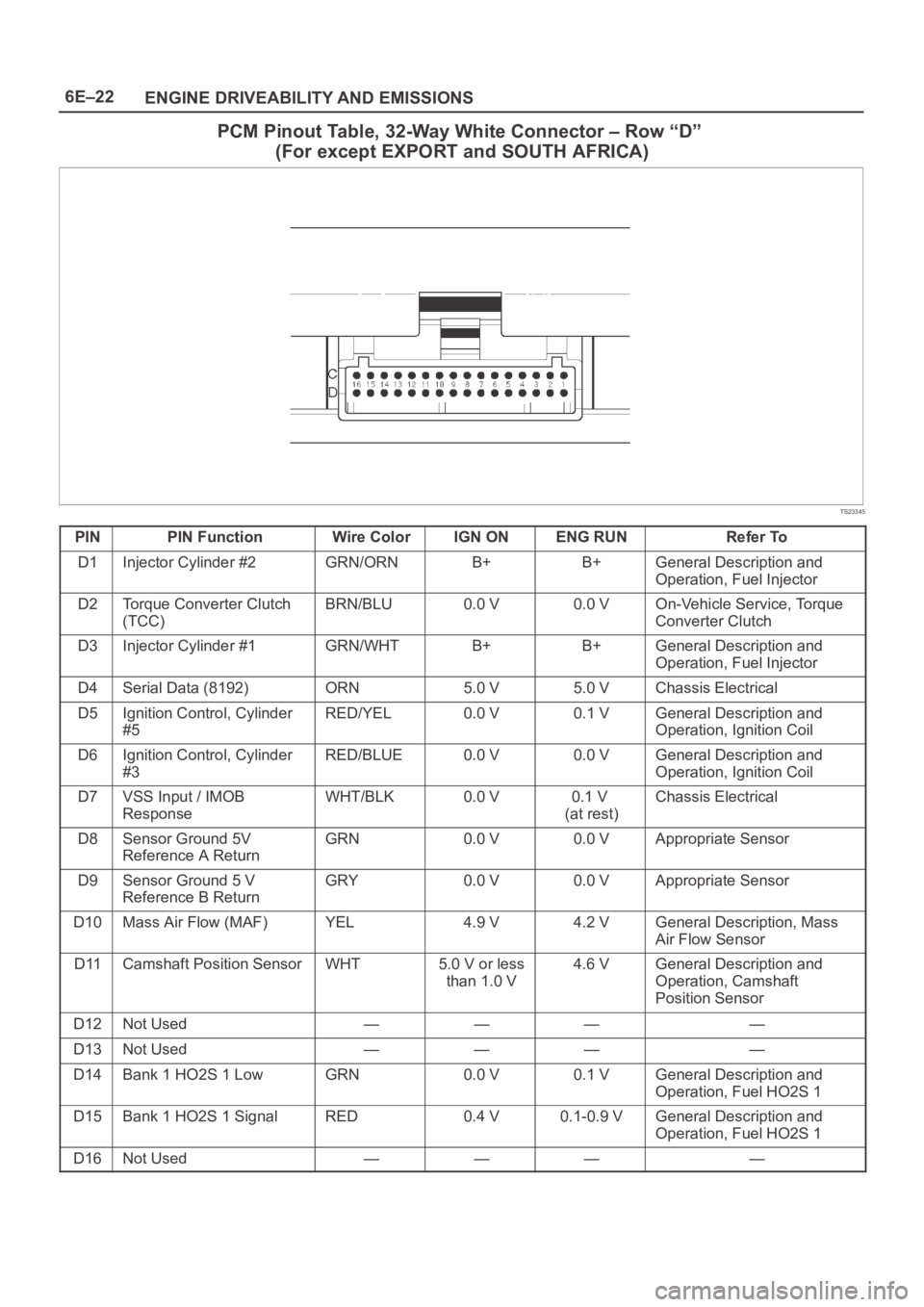
PCM Pinout Table, 32-Way White Connector – Row “D”
(For except EXPORT and SOUTH AFRICA)
TS23345
PINPIN FunctionWire ColorIGN ONENG RUNRefer To
D1Injector Cylinder #2GRN/ORNB+B+General Description and
Operation, Fuel Injector
D2Torque Converter Clutch
(TCC)BRN/BLU0.0 V0.0 VOn-Vehicle Service, Torque
Converter Clutch
D3Injector Cylinder #1GRN/WHTB+B+General Description and
Operation, Fuel Injector
D4Serial Data (8192)ORN5.0 V5.0 VChassis Electrical
D5Ignition Control, Cylinder
#5RED/YEL0.0 V0.1 VGeneral Description and
Operation, Ignition Coil
D6Ignition Control, Cylinder
#3RED/BLUE0.0 V0.0 VGeneral Description and
Operation, Ignition Coil
D7VSS Input / IMOB
ResponseWHT/BLK0.0 V0.1 V
(at rest)Chassis Electrical
D8Sensor Ground 5V
Reference A ReturnGRN0.0 V0.0 VAppropriate Sensor
D9Sensor Ground 5 V
Reference B ReturnGRY0.0 V0.0 VAppropriate Sensor
D10Mass Air Flow (MAF)YEL4.9 V4.2 VGeneral Description, Mass
Air Flow Sensor
D11Camshaft Position SensorWHT5.0 V or less
than 1.0 V4.6 VGeneral Description and
Operation, Camshaft
Position Sensor
D12Not Used————
D13Not Used————
D14Bank 1 HO2S 1 LowGRN0.0 V0.1 VGeneral Description and
Operation, Fuel HO2S 1
D15Bank 1 HO2S 1 SignalRED0.4 V0.1-0.9 VGeneral Description and
Operation, Fuel HO2S 1
D16Not Used————
Page 1155 of 6000
6E–38
ENGINE DRIVEABILITY AND EMISSIONS
General Service Information
OBD Serviceablity Issues
The list of non-vehicle faults that could affect the
performance of the OBD system has been compiled.
These non-vehicle faults vary from environmental
conditions to the quality of fuel used.
The illumination of the MIL (“Check Engine” lamp) due to
a non-vehicle fault could lead to misdiagnosis of the
vehicle, increased warranty expense and customer
dissatisfaction. The following list of non-vehicle faults
does not include every possible fault and may not apply
equally to all product lines.
Fuel Quality
Using fuel with the wrong octane rating for your vehicle
may cause driveability problems. Many of the major fuel
companies advertise that using “premium” gasoline will
improve the performance of your vehicle. Most premium
fuels use alcohol to increase the octane rating of the fuel.
Although alcohol-enhanced fuels may raise the octane
rating, the fuel’s ability to turn into vapor in cold
temperatures deteriorates. This may affect the starting
ability and cold driveability of the engine.
Low fuel levels can lead to fuel starvation, lean engine
operation, and eventually engine misfire.
Non-OEM Parts
All of the OBD diagnostics have been calibrated to run
with OEM parts. Something as simple as a
high-performance exhaust system that affects exhaust
system back pressure could potentially interfere with the
operation of the EGR valve and thereby turn on the MIL
(“Check Engine” lamp). Small leaks in the exhaust
system near the post catalyst oxygen sensor can also
cause the MIL (“Check Engine” lamp) to turn on.
Aftermarket electronics, such as cellular phones,
stereos, and anti-theft devices, may radiate EMI into the
control system if they are improperly installed. This may
cause a false sensor reading and turn on the MIL (“Check
Engine” lamp).
Environment
Temporary environmental conditions, such as localized
flooding, will have an effect on the vehicle ignition system.
If the ignition system is rain-soaked, it can temporarily
cause engine misfire and turn on the MIL (“Check Engine”
lamp).
Poor Vehicle Maintenance
The sensitivity of OBD diagnostics will cause the MIL
(“Check Engine” lamp) to turn on if the vehicle is not
maintained properly. Restricted air filters, fuel filters, and
crankcase deposits due to lack of oil changes or improper
oil viscosity can trigger actual vehicle faults that were not
previously monitored prior to OBD. Poor vehicle
maintenance can not be classified as a “non-vehicle
fault”, but with the sensitivity of OBD diagnostics, vehicle
maintenance schedules must be more closely followed.Related System Faults
Many of the OBD system diagnostics will not run if the
PCM detects a fault on a related system or component.
One example would be that if the PCM detected a Misfire
fault, the diagnostics on the catalytic converter would be
suspended until Misfire fault was repaired. If the Misfire
fault was severe enough, the catalytic converter could be
damaged due to overheating and would never set a
Catalyst DTC until the Misfire fault was repaired and the
Catalyst diagnostic was allowed to run to completion. If
this happens, the customer may have to make two trips to
the dealership in order to repair the vehicle.
Maintenance Schedule
Refer to the Maintenance Schedule.
Visual / Physical Engine Compartment
Inspection
Perform a careful visual and physical engine
compartment inspection when performing any diagnostic
procedure or diagnosing the cause of an emission test
failure. This can often lead to repairing a problem without
further steps. Use the following guidelines when
performing a visual/physical inspection:
Inspect all vacuum hoses for punches, cuts,
disconnects, and correct routing.
Inspect hoses that are difficult to see behind other
components.
Inspect all wires in the engine compartment for proper
connections, burned or chafed spots, pinched wires,
contact with sharp edges or contact with hot exhaust
manifolds or pipes.
Basic Knowledge of Tools Required
NOTE: Lack of basic knowledge of this powertrain when
performing diagnostic procedures could result in an
incorrect diagnosis or damage to powertrain
components. Do not attempt to diagnose a powertrain
problem without this basic knowledge.
A basic understanding of hand tools is necessary to effec-
tively use this section of the Service Manual.
Serial Data Communications
Class II Serial Data Communications
This vehicle utilizes the “Class II” communication system.
Each bit of information can have one of two lengths: long
or short. This allows vehicle wiring to be reduced by
transmitting and receiving multiple signals over a single
wire. The messages carried on Class II data streams are
also prioritized. If two messages attempt to establish
communications on the data line at the same time, only
the message with higher priority will continue. The device
with the lower priority message must wait. The most
significant result of this regulation is that it provides Tech 2
manufacturers with the capability to access data from any
make or model vehicle that is sold.
Page 1182 of 6000
6E–65 ENGINE DRIVEABILITY AND EMISSIONS
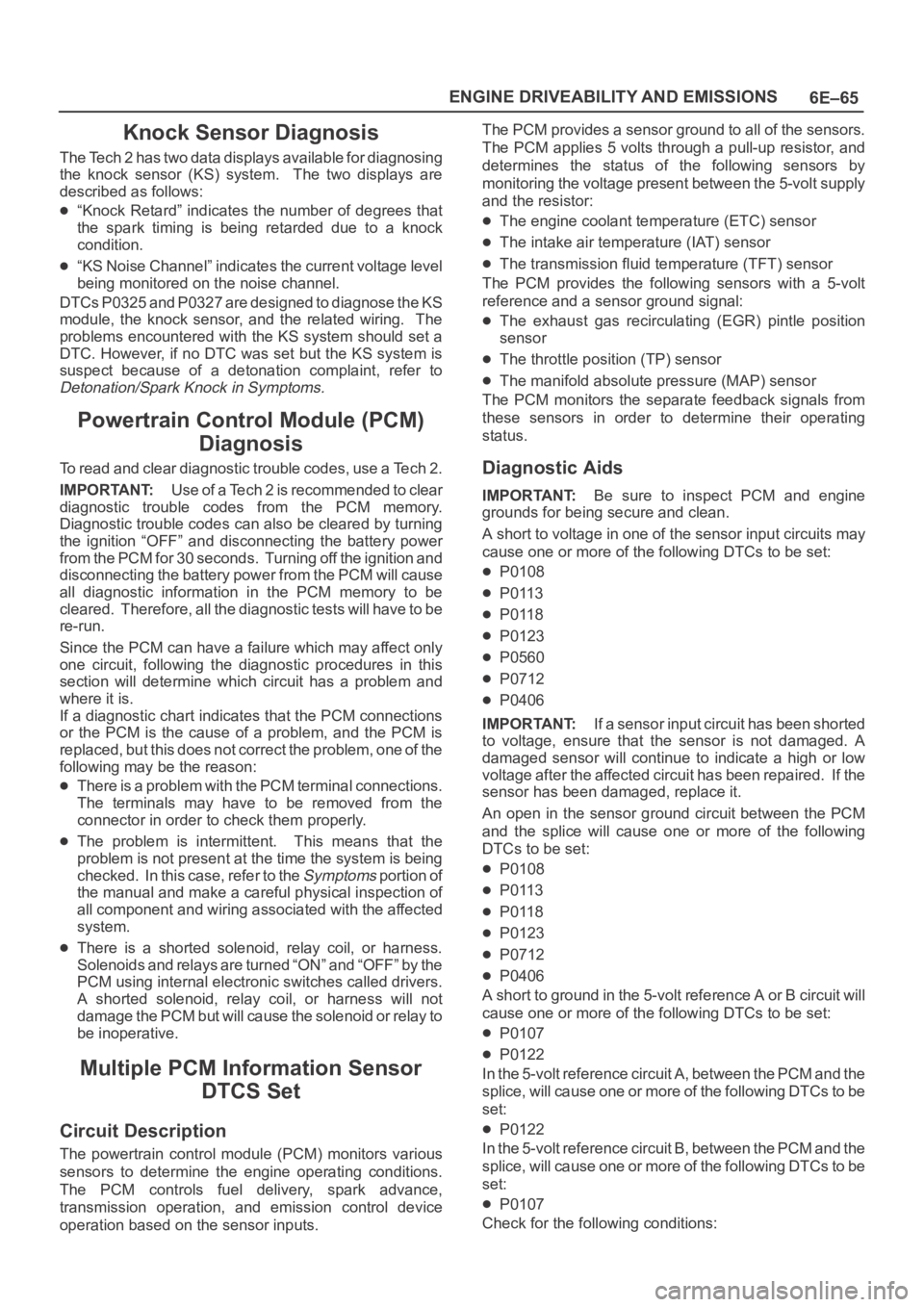
Knock Sensor Diagnosis
The Tech 2 has two data displays available for diagnosing
the knock sensor (KS) system. The two displays are
described as follows:
“Knock Retard” indicates the number of degrees that
the spark timing is being retarded due to a knock
condition.
“KS Noise Channel” indicates the current voltage level
being monitored on the noise channel.
DTCs P0325 and P0327 are designed to diagnose the KS
module, the knock sensor, and the related wiring. The
problems encountered with the KS system should set a
DTC. However, if no DTC was set but the KS system is
suspect because of a detonation complaint, refer to
Detonation/Spark Knock in Symptoms.
Powertrain Control Module (PCM)
Diagnosis
To read and clear diagnostic trouble codes, use a Tech 2.
IMPORTANT:Use of a Tech 2 is recommended to clear
diagnostic trouble codes from the PCM memory.
Diagnostic trouble codes can also be cleared by turning
the ignition “OFF” and disconnecting the battery power
from the PCM for 30 seconds. Turning off the ignition and
disconnecting the battery power from the PCM will cause
all diagnostic information in the PCM memory to be
cleared. Therefore, all the diagnostic tests will have to be
re-run.
Since the PCM can have a failure which may affect only
one circuit, following the diagnostic procedures in this
section will determine which circuit has a problem and
where it is.
If a diagnostic chart indicates that the PCM connections
or the PCM is the cause of a problem, and the PCM is
replaced, but this does not correct the problem, one of the
following may be the reason:
There is a problem with the PCM terminal connections.
The terminals may have to be removed from the
connector in order to check them properly.
The problem is intermittent. This means that the
problem is not present at the time the system is being
checked. In this case, refer to the
Symptoms p o r t i o n o f
the manual and make a careful physical inspection of
all component and wiring associated with the affected
system.
There is a shorted solenoid, relay coil, or harness.
S o l e n o i d s a n d r e l a y s a r e t u r n e d “ O N ” a n d “ O F F ” b y t h e
PCM using internal electronic switches called drivers.
A shorted solenoid, relay coil, or harness will not
damage the PCM but will cause the solenoid or relay to
be inoperative.
Multiple PCM Information Sensor
DTCS Set
Circuit Description
The powertrain control module (PCM) monitors various
sensors to determine the engine operating conditions.
The PCM controls fuel delivery, spark advance,
transmission operation, and emission control device
operation based on the sensor inputs.The PCM provides a sensor ground to all of the sensors.
The PCM applies 5 volts through a pull-up resistor, and
determines the status of the following sensors by
monitoring the voltage present between the 5-volt supply
and the resistor:
The engine coolant temperature (ETC) sensor
The intake air temperature (IAT) sensor
The transmission fluid temperature (TFT) sensor
The PCM provides the following sensors with a 5-volt
reference and a sensor ground signal:
The exhaust gas recirculating (EGR) pintle position
sensor
The throttle position (TP) sensor
The manifold absolute pressure (MAP) sensor
The PCM monitors the separate feedback signals from
these sensors in order to determine their operating
status.
Diagnostic Aids
IMPORTANT:Be sure to inspect PCM and engine
grounds for being secure and clean.
A short to voltage in one of the sensor input circuits may
cause one or more of the following DTCs to be set:
P0108
P0113
P0118
P0123
P0560
P0712
P0406
IMPORTANT:If a sensor input circuit has been shorted
to voltage, ensure that the sensor is not damaged. A
damaged sensor will continue to indicate a high or low
voltage after the affected circuit has been repaired. If the
sensor has been damaged, replace it.
An open in the sensor ground circuit between the PCM
and the splice will cause one or more of the following
DTCs to be set:
P0108
P0113
P0118
P0123
P0712
P0406
A short to ground in the 5-volt reference A or B circuit will
cause one or more of the following DTCs to be set:
P0107
P0122
In the 5-volt reference circuit A, between the PCM and the
splice, will cause one or more of the following DTCs to be
set:
P0122
In the 5-volt reference circuit B, between the PCM and the
splice, will cause one or more of the following DTCs to be
set:
P0107
Check for the following conditions:
Page 1183 of 6000
6E–66
ENGINE DRIVEABILITY AND EMISSIONS
Poor connection at PCM. Inspect the harness
connectors for backed-out terminals, improper mating,
broken locks, improperly formed or damage terminals,
and a poor terminal-to-wire connection.
Damaged harness. Inspect the wiring harness for
damage. If the harness is not damaged, observe an
affected sensor’s displayed value on the Tech 2 with
the ignition “ON” and the engine “OFF” while you move
the connectors and the wiring harnesses related to the
following sensors:
IAT
ECT
TP
MAP
EGR
TFT
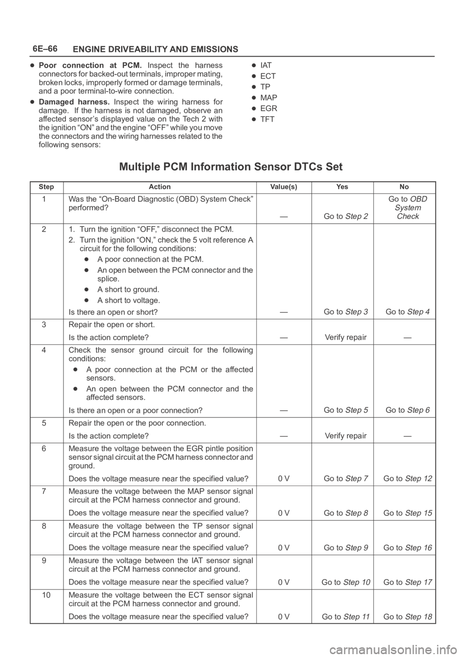
Multiple PCM Information Sensor DTCs Set
StepActionVa l u e ( s )Ye sNo
1Was the “On-Board Diagnostic (OBD) System Check”
performed?
—Go to Step 2
Go to OBD
System
Check
21. Turn the ignition “OFF,” disconnect the PCM.
2. Turn the ignition “ON,” check the 5 volt reference A
circuit for the following conditions:
A poor connection at the PCM.
An open between the PCM connector and the
splice.
A short to ground.
A short to voltage.
Is there an open or short?
—Go to Step 3Go to Step 4
3Repair the open or short.
Is the action complete?
—Verify repair—
4Check the sensor ground circuit for the following
conditions:
A poor connection at the PCM or the affected
sensors.
An open between the PCM connector and the
affected sensors.
Is there an open or a poor connection?
—Go to Step 5Go to Step 6
5Repair the open or the poor connection.
Is the action complete?
—Verify repair—
6Measure the voltage between the EGR pintle position
sensor signal circuit at the PCM harness connector and
ground.
Does the voltage measure near the specified value?
0 VGo to Step 7Go to Step 12
7Measure the voltage between the MAP sensor signal
circuit at the PCM harness connector and ground.
Does the voltage measure near the specified value?
0 VGo to Step 8Go to Step 15
8Measure the voltage between the TP sensor signal
circuit at the PCM harness connector and ground.
Does the voltage measure near the specified value?
0 VGo to Step 9Go to Step 16
9Measure the voltage between the IAT sensor signal
circuit at the PCM harness connector and ground.
Does the voltage measure near the specified value?
0 VGo to Step 10Go to Step 17
10Measure the voltage between the ECT sensor signal
circuit at the PCM harness connector and ground.
Does the voltage measure near the specified value?
0 VGo to Step 11Go to Step 18
Page 1213 of 6000

6E–96
ENGINE DRIVEABILITY AND EMISSIONS
Knock Sensor (KS) System Check
(Engine Knock, Poor Performance, or Poor Economy)
StepActionVa l u e ( s )Ye sNo
1Is DTC P0325 or P0327 set?
—
Go to DTC
P0325 or
DTC P0327
Go to Step 2
2Run the engine at 1500 RPM.
Is there an internal engine knock?
—Go to Step 3Go to Step 4
3Repair the mechanical problem.
Is the action complete?
—Verify repair—
41. Install Tech 2.
2. Turn the ignition “ON.”
3. Cycle through the list until “Knock Retard” is
displayed.
Is knock retard at the specified value?
0Go to Step 6Go to Step 7
5Replace the PCM.
IMPORTANT:The replacement PCM must be
programmed. Refer to
UBS 98model year Immobilizer
Workshop Manual.
Is the action complete?—Verify repair—
61. Start the engine.
2. Monitor the knock retard display on Tech 2 while
changing the throttle setting to place different loads
on the engine.
Is knock retard at the specified value? (Turn the ignition
“OFF.”)
0Go to Step 9Go to Step 7
71. At the rear of the engine, behind the rear fuel
injector on the lift side, disconnect the 2-wire knock
sensor harness connector.
2. Attach the positive lead of DVM to B+.
3. On the m ain harness side of the connector, use th e
negative lead of the DVM to probe the connector pin
that is connected to the black wire.
Dose the DVM indicate the specified value?
(Reconnect the knock sensor harness.)
B+Go to Step 9Go to Step 8
8Repair the open black wire ground for the shield which
prevents stray electromagnetic pulses from affecting
the knock signal.
Is the action complete?
—Verify repair—
91. Reconnect the wire harness.
2. Set a DVM to AC voltage.
3. With the DVM, backprobe the PCM connector at
A2.
4. Tap the engine lift brackprobe with a socket
extension.
Did the DVM show an increase in AC voltage while
tapping on the lift bracket?
—System OKGo to Step 10
10Replace the knock sensor.
Is the action complete?
—Verify repair—