1998 OPEL FRONTERA turn signal
[x] Cancel search: turn signalPage 3524 of 6000
9J1–37
RESTRAINT CONTROL SYSTEM
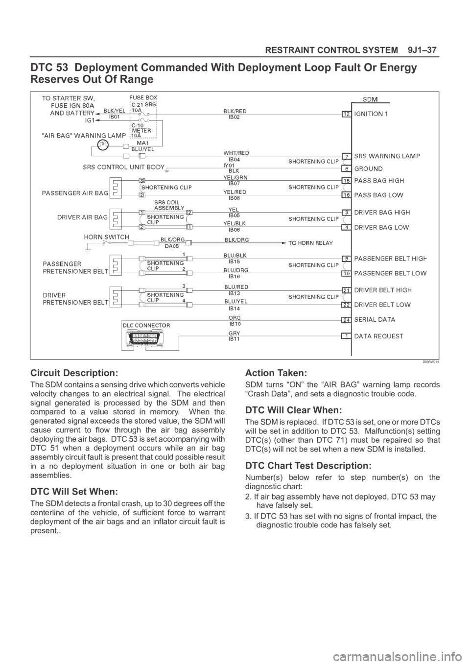
DTC 53 Deployment Commanded With Deployment Loop Fault Or Energy
Reserves Out Of Range
D09RW014
Circuit Description:
The SDM contains a sensing drive which converts vehicle
velocity changes to an electrical signal. The electrical
signal generated is processed by the SDM and then
compared to a value stored in memory. When the
generated signal exceeds the stored value, the SDM will
cause current to flow through the air bag assembly
deploying the air bags. DTC 53 is set accompanying with
DTC 51 when a deployment occurs while an air bag
assembly circuit fault is present that could possible result
in a no deployment situation in one or both air bag
assemblies.
DTC Will Set When:
The SDM detects a frontal crash, up to 30 degrees off the
centerline of the vehicle, of sufficient force to warrant
deployment of the air bags and an inflator circuit fault is
present..
Action Taken:
SDM turns “ON” the “AIR BAG” warning lamp records
“Crash Data”, and sets a diagnostic trouble code.
DTC Will Clear When:
The SDM is replaced. If DTC 53 is set, one or more DTCs
will be set in addition to DTC 53. Malfunction(s) setting
DTC(s) (other than DTC 71) must be repaired so that
DTC(s) will not be set when a new SDM is installed.
DTC Chart Test Description:
Number(s) below refer to step number(s) on the
diagnostic chart:
2. If air bag assembly have not deployed, DTC 53 may
have falsely set.
3. If DTC 53 has set with no signs of frontal impact, the
diagnostic trouble code has falsely set.
Page 3550 of 6000
9J1–63
RESTRAINT CONTROL SYSTEM
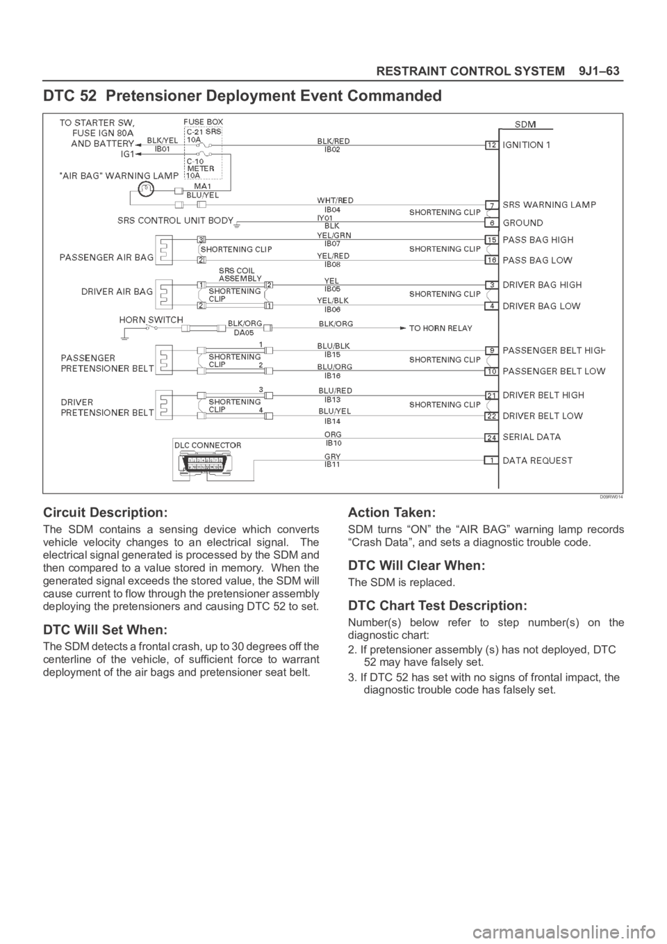
DTC 52 Pretensioner Deployment Event Commanded
D09RW014
Circuit Description:
The SDM contains a sensing device which converts
vehicle velocity changes to an electrical signal. The
electrical signal generated is processed by the SDM and
then compared to a value stored in memory. When the
generated signal exceeds the stored value, the SDM will
cause current to flow through the pretensioner assembly
deploying the pretensioners and causing DTC 52 to set.
DTC Will Set When:
The SDM detects a frontal crash, up to 30 degrees off the
centerline of the vehicle, of sufficient force to warrant
deployment of the air bags and pretensioner seat belt.
Action Taken:
SDM turns “ON” the “AIR BAG” warning lamp records
“Crash Data”, and sets a diagnostic trouble code.
DTC Will Clear When:
The SDM is replaced.
DTC Chart Test Description:
Number(s) below refer to step number(s) on the
diagnostic chart:
2. If pretensioner assembly (s) has not deployed, DTC
52 may have falsely set.
3. If DTC 52 has set with no signs of frontal impact, the
diagnostic trouble code has falsely set.
Page 3552 of 6000
10A–1
CRUISE CONTROL SYSTEM
CONTROL SYSTEM
CRUISE CONTROL SYSTEM
CONTENTS
Service Precaution 10A–1. . . . . . . . . . . . . . . . . . . . . .
General Description 10A–1. . . . . . . . . . . . . . . . . . . . .
Diagnosis 10A–2. . . . . . . . . . . . . . . . . . . . . . . . . . . . . .
Brake Switch 10A–2. . . . . . . . . . . . . . . . . . . . . . . . . . .
Removal 10A–2. . . . . . . . . . . . . . . . . . . . . . . . . . . . .
Installation 10A–2. . . . . . . . . . . . . . . . . . . . . . . . . . . .
Adjustment 10A–3. . . . . . . . . . . . . . . . . . . . . . . . . . .
Clutch Switch 10A–3. . . . . . . . . . . . . . . . . . . . . . . . . . .
Removal and Installation 10A–3. . . . . . . . . . . . . . .
Adjustment 10A–3. . . . . . . . . . . . . . . . . . . . . . . . . . .
Starter Switch 10A–4. . . . . . . . . . . . . . . . . . . . . . . . . . .
Removal 10A–4. . . . . . . . . . . . . . . . . . . . . . . . . . . . .
Installation 10A–4. . . . . . . . . . . . . . . . . . . . . . . . . . . .
Cruise Control Main Switch 10A–5. . . . . . . . . . . . . . . Removal 10A–5. . . . . . . . . . . . . . . . . . . . . . . . . . . . .
Installation 10A–5. . . . . . . . . . . . . . . . . . . . . . . . . . . .
Cruise Control Switch (Combination Switch) 10A–5
Removal and Installation 10A–5. . . . . . . . . . . . . . .
Cruise Control Unit 10A–6. . . . . . . . . . . . . . . . . . . . . .
Removal 10A–6. . . . . . . . . . . . . . . . . . . . . . . . . . . . .
Installation 10A–6. . . . . . . . . . . . . . . . . . . . . . . . . . . .
Cruise Actuator 10A–7. . . . . . . . . . . . . . . . . . . . . . . . .
Actuator Cable Diagram (LHD) 10A–7. . . . . . . . . .
Actuator Cable Diagram (RHD) 10A–7. . . . . . . . . .
Removal 10A–8. . . . . . . . . . . . . . . . . . . . . . . . . . . . .
Installation 10A–8. . . . . . . . . . . . . . . . . . . . . . . . . . . .
Mode Switch 10A–8. . . . . . . . . . . . . . . . . . . . . . . . . . . .
Removal and Installation 10A–8. . . . . . . . . . . . . . .
Service Precaution
WARNING: IF SO EQUIPPED WITH A
SUPPLEMENTAL RESTRAINT SYSTEM (SRS),
REFER TO THE SRS COMPONENT AND WIRING
LOCATION VIEW IN ORDER TO DETERMINE
WHETHER YOU ARE PERFORMING SERVICE ON OR
NEAR THE SRS COMPONENTS OR THE SRS
WIRING. WHEN YOU ARE PERFORMING SERVICE
ON OR NEAR THE SRS COMPONENTS OR THE SRS
WIRING, REFER TO THE SRS SERVICE
INFORMATION. FAILURE TO FOLLOW WARNINGS
COULD RESULT IN POSSIBLE AIR BAG
DEPLOYMENT, PERSONAL INJURY, OR
OTHERWISE UNNEEDED SRS SYSTEM REPAIRS.
CAUTION: Always use the correct fastener in the
proper location. When you replace a fastener, use
ONLY the exact part number for that application.
ISUZU will call out those fasteners that require a
replacement after removal. ISUZU will also call out
the fasteners that require thread lockers or thread
sealant. UNLESS OTHERWISE SPECIFIED, do not
use supplemental coatings (Paints, greases, or other
corrosion inhibitors) on threaded fasteners or
fastener joint interfaces. Generally, such coatings
adversely affect the fastener torque and the joint
clamping force, and may damage the fastener. When
you install fasteners, use the correct tightening
sequence and specifications. Following these
instructions can help you avoid damage to parts and
systems.
General Description
The cruise control keeps the vehicle running at a fixed
speed until a signal canceling this fixed speed is received .
When the main switch “AUTO CRUISE” is turned on with
the vehicle in the running mode, the battery voltage is
applied to the control unit. When a signal from the control
switch is input to the control unit while the vehicle is in this
state, the cruise control actuator is activated to operate
the system. Also, while the system is operating, the
“AUTO CRUISE” indicator light in the meter assembly
lights up.
1. SET/COAST Switch Function
1.Set Function: When the SET/COAST switch is
pressed and released with the main switch on, the
speed at which the vehicle is running at that moment
is stored in the memory, and the vehicle automatically
runs at the stored speed.
2.Coast-down Function: When the SET/COAST
switch is kept on while the vehicle in running, the
vehicle decelerates during that time. The speed at
which vehicle is running when the control switch is
turned off is stored in the memory, and the vehicle
automatically returns to the stored speed.
3.Tap-down Function: When the SET/COAST switch
is turned on and off instantaneously while the vehicle
is running, the vehicle decelerates a mile for each
on/off operation. The vehicle speed at which the
vehicle was running when the SET/COAST was
turned off last is stored in the memory, and the vehicle
automatically returns to this stored speed.
Page 4054 of 6000
4B1–9 DRIVE LINE CONTROL SYSTEM (SHIFT ON THE FLY)
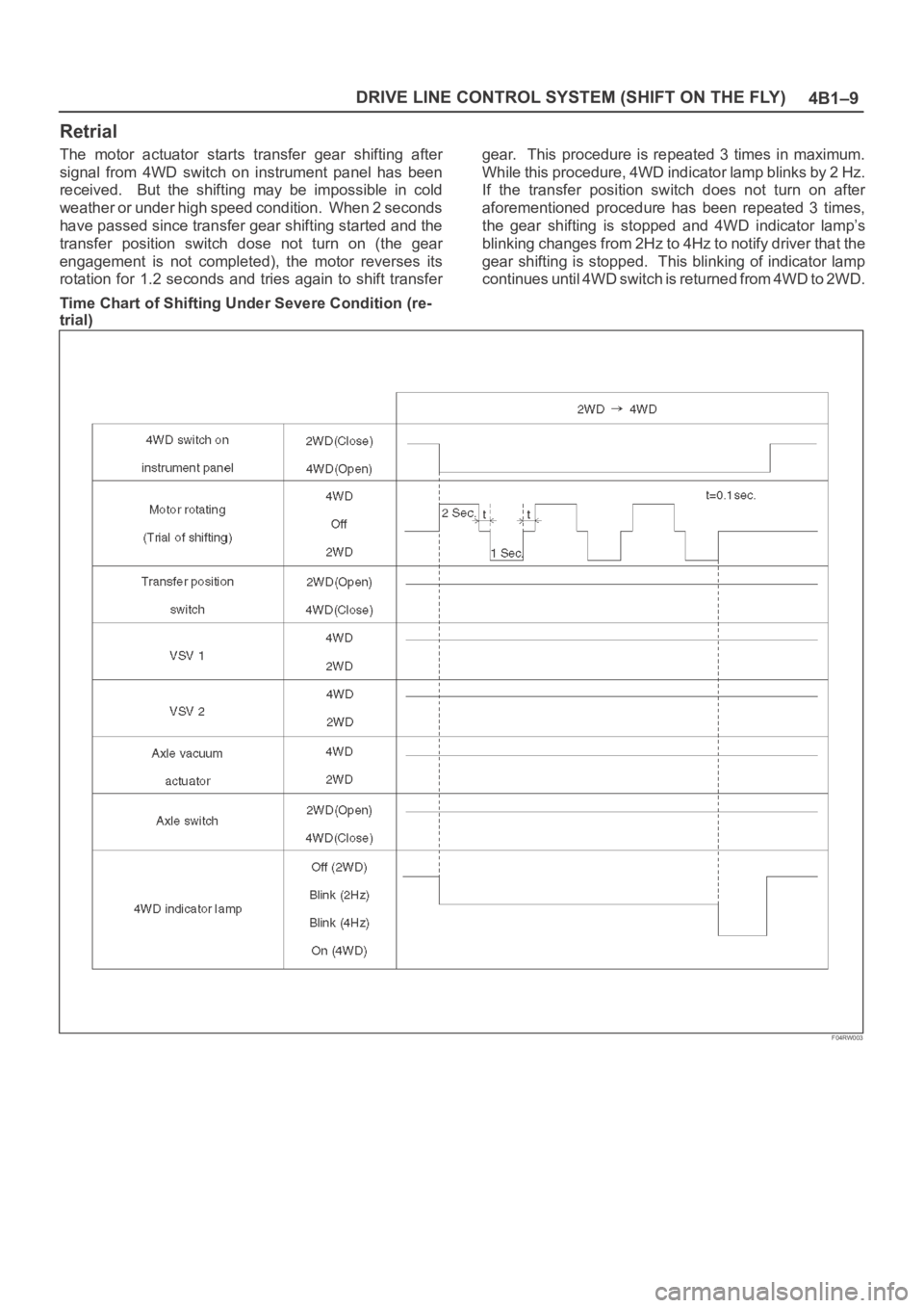
Retrial
The motor actuator starts transfer gear shifting after
signal from 4WD switch on instrument panel has been
received. But the shifting may be impossible in cold
weather or under high speed condition. When 2 seconds
have passed since transfer gear shifting started and the
transfer position switch dose not turn on (the gear
engagement is not completed), the motor reverses its
rotation for 1.2 seconds and tries again to shift transfergear. This procedure is repeated 3 times in maximum.
While this procedure, 4WD indicator lamp blinks by 2 Hz.
If the transfer position switch does not turn on after
aforementioned procedure has been repeated 3 times,
the gear shifting is stopped and 4WD indicator lamp’s
blinking changes from 2Hz to 4Hz to notify driver that the
gear shifting is stopped. This blinking of indicator lamp
continues until 4WD switch is returned from 4WD to 2WD.
Time Chart of Shifting Under Severe Condition (re-
trial)
F04RW003
Page 4055 of 6000
4B1–10
DRIVE LINE CONTROL SYSTEM (SHIFT ON THE FLY)
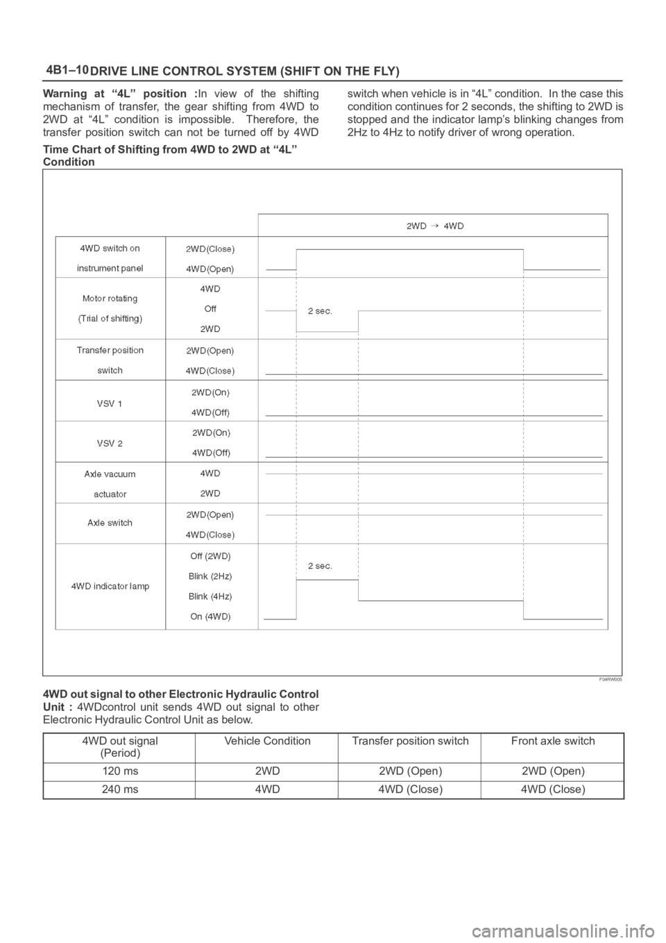
Warning at “4L” position :In view of the shifting
mechanism of transfer, the gear shifting from 4WD to
2WD at “4L” condition is impossible. Therefore, the
transfer position switch can not be turned off by 4WDswitch when vehicle is in “4L” condition. In the case this
condition continues for 2 seconds, the shifting to 2WD is
stopped and the indicator lamp’s blinking changes from
2Hz to 4Hz to notify driver of wrong operation.
Time Chart of Shifting from 4WD to 2WD at “4L”
Condition
F04RW005
4WD out signal to other Electronic Hydraulic Control
Unit : 4WDcontrol unit sends 4WD out signal to other
Electronic Hydraulic Control Unit as below.
4WD out signal
(Period)
Vehicle ConditionTransfer position switchFront axle switch
120 ms2WD2WD (Open)2WD (Open)
240 ms4WD4WD (Close)4WD (Close)
Page 4086 of 6000
4B2–3 DRIVE LINE CONTROL SYSTEM (TOD)
condition, determines the optimum torque based on the
feedback control logic, and increases the torque to the
front wheels.
The control unit uses the signal from the throttle position
sensor to predict the future vehicle condition and the
intention of the driver with respect to acceleration and
deceleration, and determines the initial torque distribution
using these data and the information from the speed
sensors.
In case of small circle turning in the parking lot, for
example, the control unit minimizes the clutch pressing
force to restrict a braking phenomenon. When the ABS
becomes active, the control unit optimizes the clutch
pressing force to ensure stable braking.
TOD Indicator Control
The TOD indicator on the instrument panel informs the
driver of the current working status of the transfer unit.
The information consists of two items: the drive mode
(2H, TOD, 4L, transition) and the torque split status of the
TOD (torque distribution level). The indicator can display
occasional errors and corresponding error codes.
Page 4091 of 6000
DRIVE LINE CONTROL SYSTEM (TOD) 4B2–8
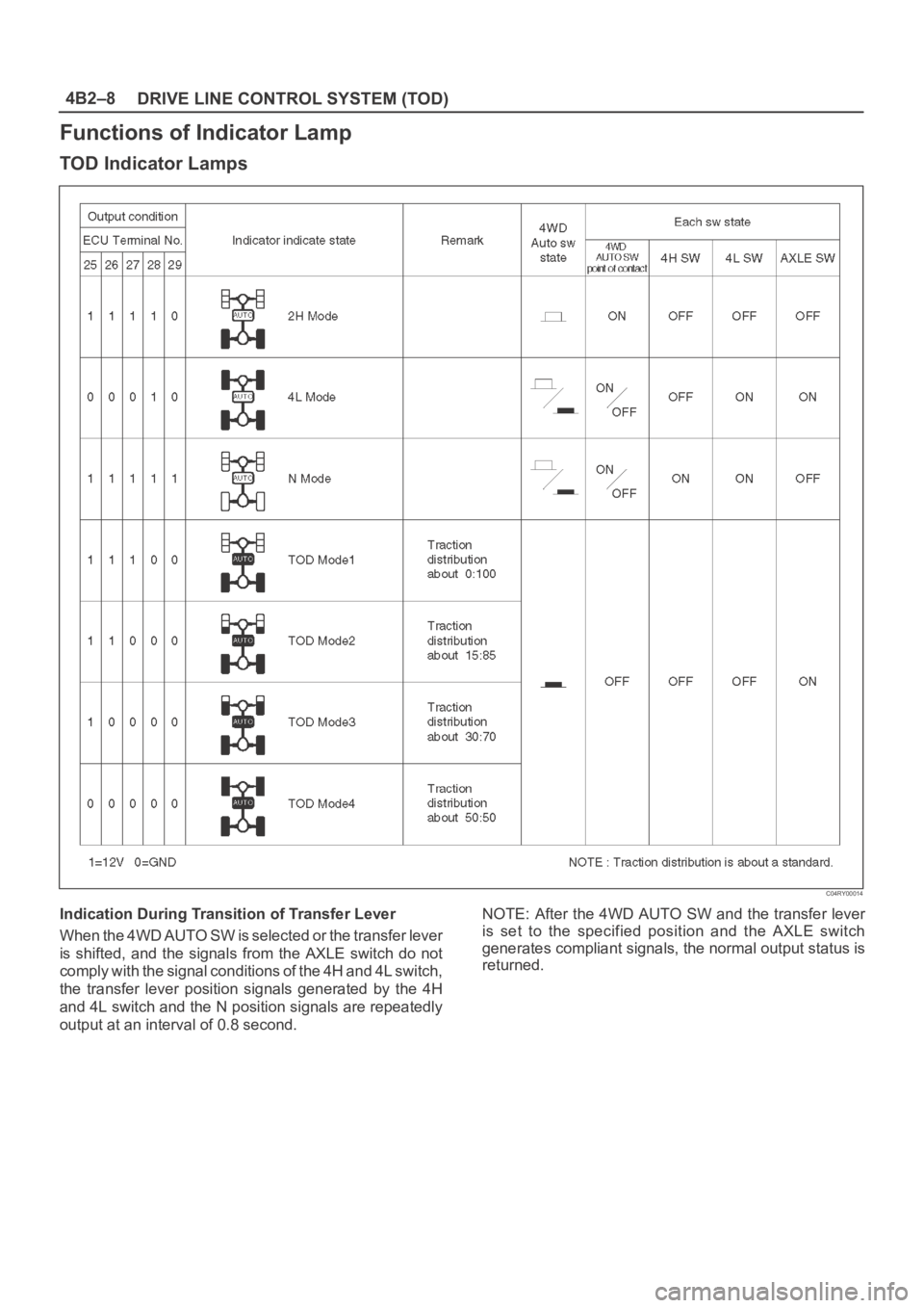
Functions of Indicator Lamp
TOD Indicator Lamps
C04RY00014
Indication During Transition of Transfer Lever
When the 4WD AUTO SW is selected or the transfer lever
is shifted, and the signals from the AXLE switch do not
comply with the signal conditions of the 4H and 4L switch,
the transfer lever position signals generated by the 4H
and 4L switch and the N position signals are repeatedly
output at an interval of 0.8 second.NOTE: After the 4WD AUTO SW and the transfer lever
is set to the specified position and the AXLE switch
generates compliant signals, the normal output status is
returned.
Page 4093 of 6000
DRIVE LINE CONTROL SYSTEM (TOD) 4B2–10
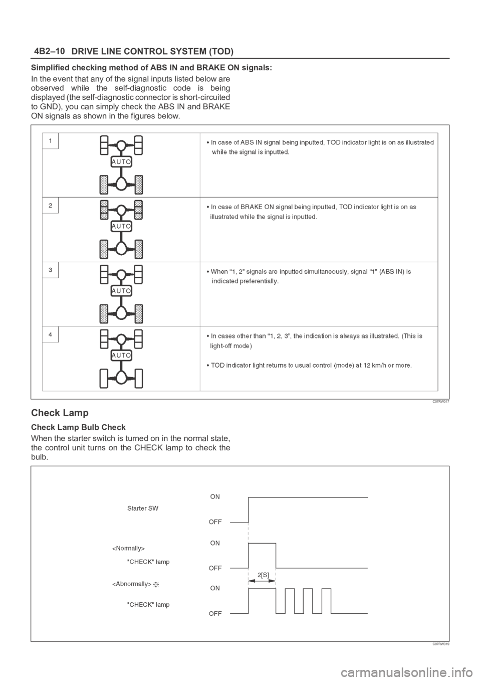
Simplified checking method of ABS IN and BRAKE ON signals:
In the event that any of the signal inputs listed below are
observed while the self-diagnostic code is being
displayed (the self-diagnostic connector is short-circuited
to GND), you can simply check the ABS IN and BRAKE
ON signals as shown in the figures below.
C07RW017
Check Lamp
Check Lamp Bulb Check
When the starter switch is turned on in the normal state,
the control unit turns on the CHECK lamp to check the
bulb.
C07RW019