1998 OPEL FRONTERA turn signal
[x] Cancel search: turn signalPage 4861 of 6000
6E–204
ENGINE DRIVEABILITY AND EMISSIONS
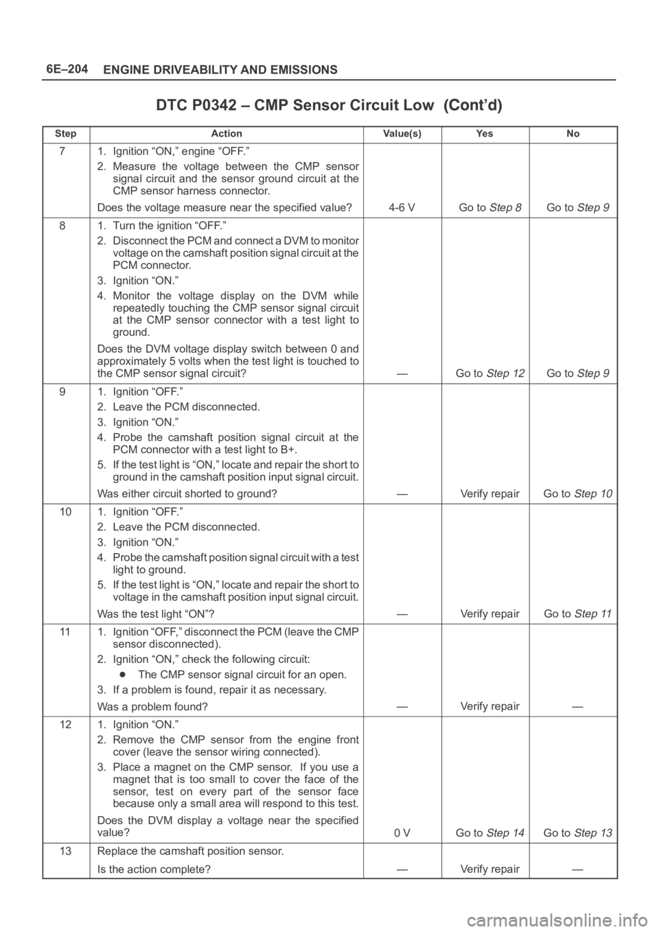
DTC P0342 – CMP Sensor Circuit Low
StepNo Ye s Va l u e ( s ) Action
71. Ignition “ON,” engine “OFF.”
2. Measure the voltage between the CMP sensor
signal circuit and the sensor ground circuit at the
CMP sensor harness connector.
Does the voltage measure near the specified value?
4-6 VGo to Step 8Go to Step 9
81. Turn the ignition “OFF.”
2. Disconnect the PCM and connect a DVM to monitor
voltage on the camshaft position signal circuit at the
PCM connector.
3. Ignition “ON.”
4. Monitor the voltage display on the DVM while
repeatedly touching the CMP sensor signal circuit
at the CMP sensor connector with a test light to
ground.
Does the DVM voltage display switch between 0 and
approximately 5 volts when the test light is touched to
the CMP sensor signal circuit?
—Go to Step 12Go to Step 9
91. Ignition “OFF.”
2. Leave the PCM disconnected.
3. Ignition “ON.”
4. Probe the camshaft position signal circuit at the
PCM connector with a test light to B+.
5. If the test light is “ON,” locate and repair the short to
ground in the camshaft position input signal circuit.
Was either circuit shorted to ground?
—Verify repairGo to Step 10
101. Ignition “OFF.”
2. Leave the PCM disconnected.
3. Ignition “ON.”
4. Probe the camshaft position signal circuit with a test
light to ground.
5. If the test light is “ON,” locate and repair the short to
voltage in the camshaft position input signal circuit.
Was the test light “ON”?
—Verify repairGo to Step 11
111. Ignition “OFF,” disconnect the PCM (leave the CMP
sensor disconnected).
2. Ignition “ON,” check the following circuit:
The CMP sensor signal circuit for an open.
3. If a problem is found, repair it as necessary.
Was a problem found?
—Verify repair—
121. Ignition “ON.”
2. Remove the CMP sensor from the engine front
cover (leave the sensor wiring connected).
3. Place a magnet on the CMP sensor. If you use a
magnet that is too small to cover the face of the
sensor, test on every part of the sensor face
because only a small area will respond to this test.
Does the DVM display a voltage near the specified
value?
0 VGo to Step 14Go to Step 13
13Replace the camshaft position sensor.
Is the action complete?
—Verify repair—
Page 4863 of 6000
6E–206
ENGINE DRIVEABILITY AND EMISSIONS
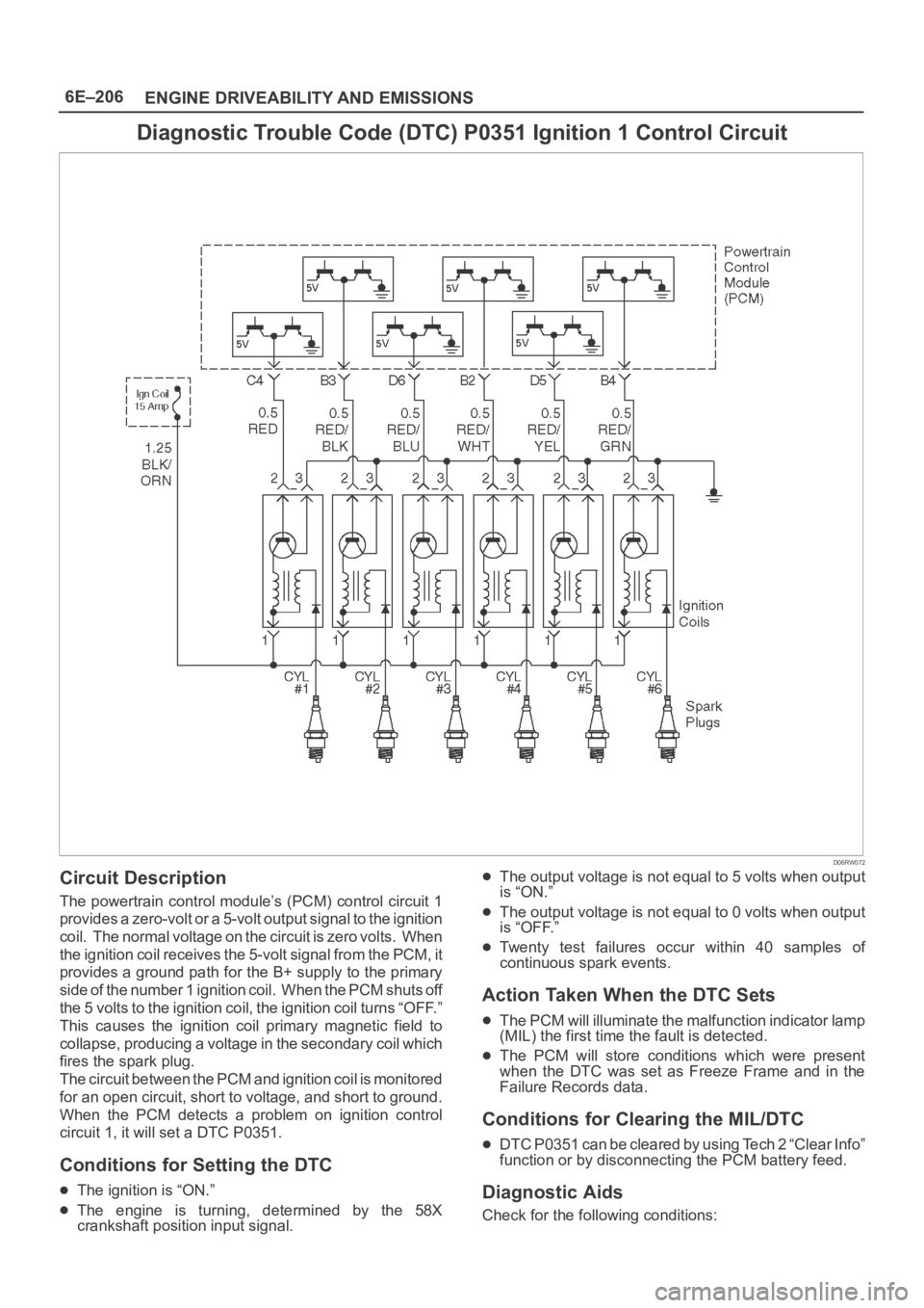
Diagnostic Trouble Code (DTC) P0351 Ignition 1 Control Circuit
D06RW072
Circuit Description
The powertrain control module’s (PCM) control circuit 1
provides a zero-volt or a 5-volt output signal to the ignition
coil. The normal voltage on the circuit is zero volts. When
the ignition coil receives the 5-volt signal from the PCM, it
provides a ground path for the B+ supply to the primary
side of the number 1 ignition coil. When the PCM shuts off
the 5 volts to the ignition coil, the ignition coil turns “OFF.”
This causes the ignition coil primary magnetic field to
collapse, producing a voltage in the secondary coil which
fires the spark plug.
The circuit between the PCM and ignition coil is monitored
for an open circuit, short to voltage, and short to ground.
When the PCM detects a problem on ignition control
circuit 1, it will set a DTC P0351.
Conditions for Setting the DTC
The ignition is “ON.”
The engine is turning, determined by the 58X
crankshaft position input signal.
The output voltage is not equal to 5 volts when output
is “ON.”
The output voltage is not equal to 0 volts when output
is “OFF.”
Twenty test failures occur within 40 samples of
continuous spark events.
Action Taken When the DTC Sets
The PCM will illuminate the malfunction indicator lamp
(MIL) the first time the fault is detected.
The PCM will store conditions which were present
when the DTC was set as Freeze Frame and in the
Failure Records data.
Conditions for Clearing the MIL/DTC
DTC P0351 can be cleared by using Tech 2 “Clear Info”
function or by disconnecting the PCM battery feed.
Diagnostic Aids
Check for the following conditions:
Page 4866 of 6000
6E–209 ENGINE DRIVEABILITY AND EMISSIONS
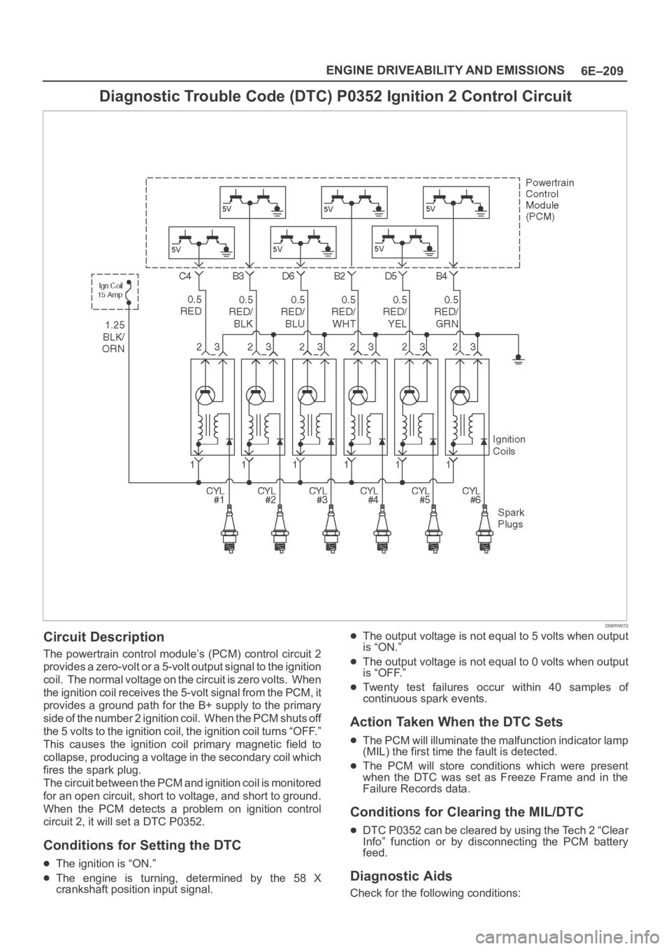
Diagnostic Trouble Code (DTC) P0352 Ignition 2 Control Circuit
D06RW072
Circuit Description
The powertrain control module’s (PCM) control circuit 2
provides a zero-volt or a 5-volt output signal to the ignition
coil. The normal voltage on the circuit is zero volts. When
the ignition coil receives the 5-volt signal from the PCM, it
provides a ground path for the B+ supply to the primary
side of the number 2 ignition coil. When the PCM shuts off
the 5 volts to the ignition coil, the ignition coil turns “OFF.”
This causes the ignition coil primary magnetic field to
collapse, producing a voltage in the secondary coil which
fires the spark plug.
The circuit between the PCM and ignition coil is monitored
for an open circuit, short to voltage, and short to ground.
When the PCM detects a problem on ignition control
circuit 2, it will set a DTC P0352.
Conditions for Setting the DTC
The ignition is “ON.”
The engine is turning, determined by the 58 X
crankshaft position input signal.
The output voltage is not equal to 5 volts when output
is “ON.”
The output voltage is not equal to 0 volts when output
is “OFF.”
Twenty test failures occur within 40 samples of
continuous spark events.
Action Taken When the DTC Sets
The PCM will illuminate the malfunction indicator lamp
(MIL) the first time the fault is detected.
The PCM will store conditions which were present
when the DTC was set as Freeze Frame and in the
Failure Records data.
Conditions for Clearing the MIL/DTC
DTC P0352 can be cleared by using the Tech 2 “Clear
Info” function or by disconnecting the PCM battery
feed.
Diagnostic Aids
Check for the following conditions:
Page 4869 of 6000
6E–212
ENGINE DRIVEABILITY AND EMISSIONS
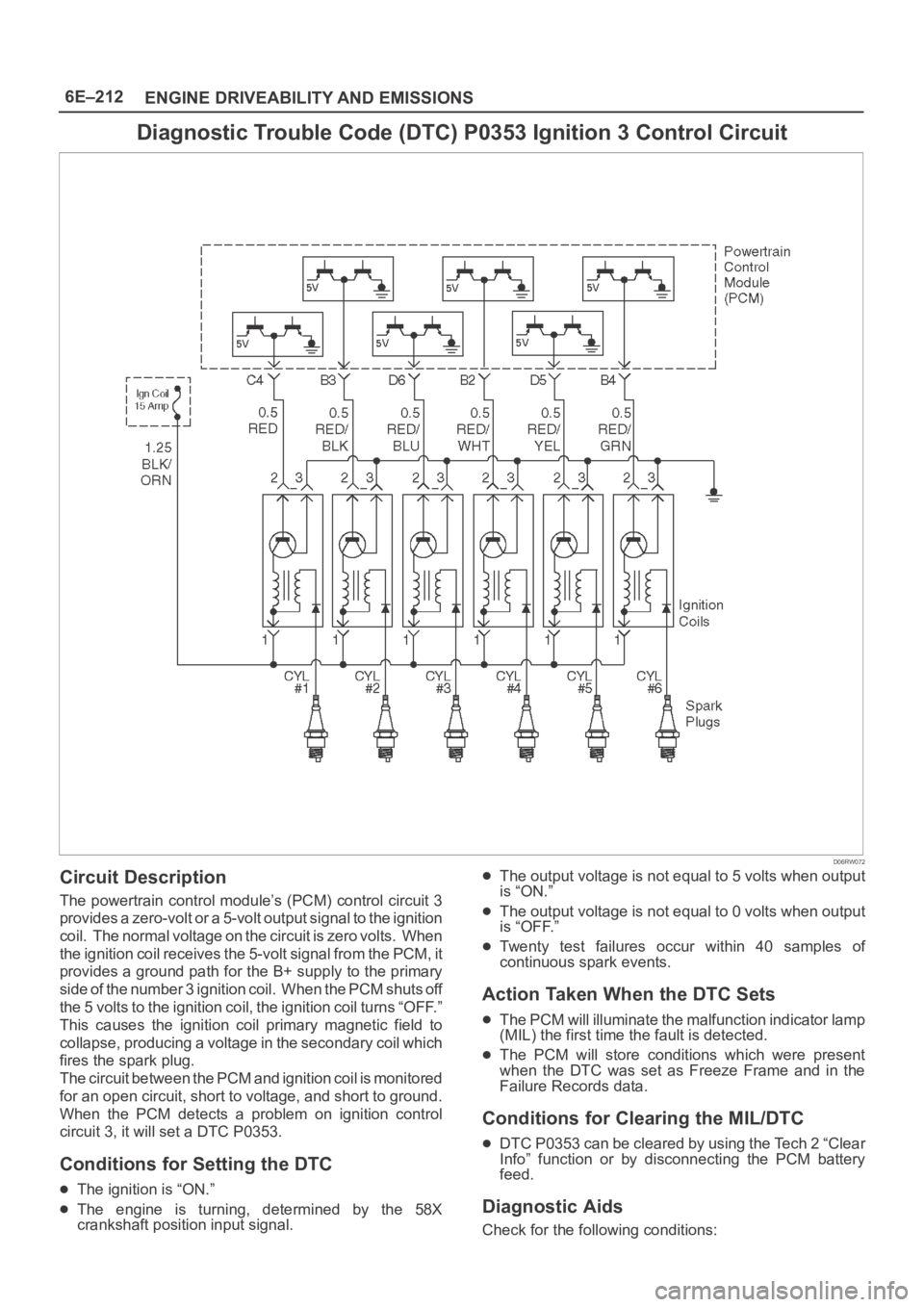
Diagnostic Trouble Code (DTC) P0353 Ignition 3 Control Circuit
D06RW072
Circuit Description
The powertrain control module’s (PCM) control circuit 3
provides a zero-volt or a 5-volt output signal to the ignition
coil. The normal voltage on the circuit is zero volts. When
the ignition coil receives the 5-volt signal from the PCM, it
provides a ground path for the B+ supply to the primary
side of the number 3 ignition coil. When the PCM shuts off
the 5 volts to the ignition coil, the ignition coil turns “OFF.”
This causes the ignition coil primary magnetic field to
collapse, producing a voltage in the secondary coil which
fires the spark plug.
The circuit between the PCM and ignition coil is monitored
for an open circuit, short to voltage, and short to ground.
When the PCM detects a problem on ignition control
circuit 3, it will set a DTC P0353.
Conditions for Setting the DTC
The ignition is “ON.”
The engine is turning, determined by the 58X
crankshaft position input signal.
The output voltage is not equal to 5 volts when output
is “ON.”
The output voltage is not equal to 0 volts when output
is “OFF.”
Twenty test failures occur within 40 samples of
continuous spark events.
Action Taken When the DTC Sets
The PCM will illuminate the malfunction indicator lamp
(MIL) the first time the fault is detected.
The PCM will store conditions which were present
when the DTC was set as Freeze Frame and in the
Failure Records data.
Conditions for Clearing the MIL/DTC
DTC P0353 can be cleared by using the Tech 2 “Clear
Info” function or by disconnecting the PCM battery
feed.
Diagnostic Aids
Check for the following conditions:
Page 4872 of 6000
6E–215 ENGINE DRIVEABILITY AND EMISSIONS
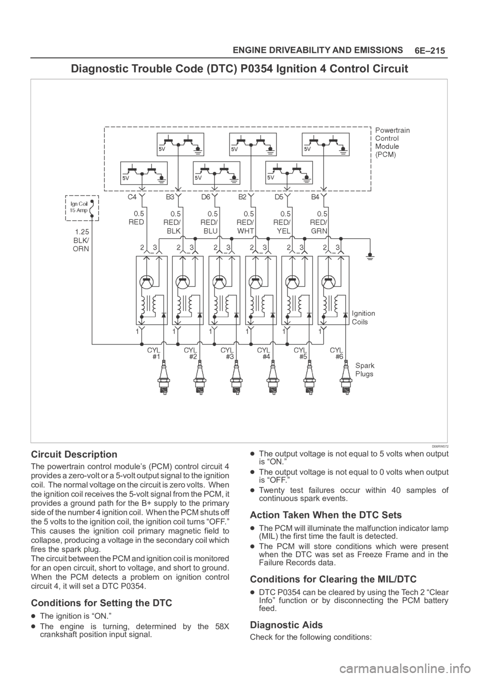
Diagnostic Trouble Code (DTC) P0354 Ignition 4 Control Circuit
D06RW072
Circuit Description
The powertrain control module’s (PCM) control circuit 4
provides a zero-volt or a 5-volt output signal to the ignition
coil. The normal voltage on the circuit is zero volts. When
the ignition coil receives the 5-volt signal from the PCM, it
provides a ground path for the B+ supply to the primary
side of the number 4 ignition coil. When the PCM shuts off
the 5 volts to the ignition coil, the ignition coil turns “OFF.”
This causes the ignition coil primary magnetic field to
collapse, producing a voltage in the secondary coil which
fires the spark plug.
The circuit between the PCM and ignition coil is monitored
for an open circuit, short to voltage, and short to ground.
When the PCM detects a problem on ignition control
circuit 4, it will set a DTC P0354.
Conditions for Setting the DTC
The ignition is “ON.”
The engine is turning, determined by the 58X
crankshaft position input signal.
The output voltage is not equal to 5 volts when output
is “ON.”
The output voltage is not equal to 0 volts when output
is “OFF.”
Twenty test failures occur within 40 samples of
continuous spark events.
Action Taken When the DTC Sets
The PCM will illuminate the malfunction indicator lamp
(MIL) the first time the fault is detected.
The PCM will store conditions which were present
when the DTC was set as Freeze Frame and in the
Failure Records data.
Conditions for Clearing the MIL/DTC
DTC P0354 can be cleared by using the Tech 2 “Clear
Info” function or by disconnecting the PCM battery
feed.
Diagnostic Aids
Check for the following conditions:
Page 4875 of 6000
6E–218
ENGINE DRIVEABILITY AND EMISSIONS
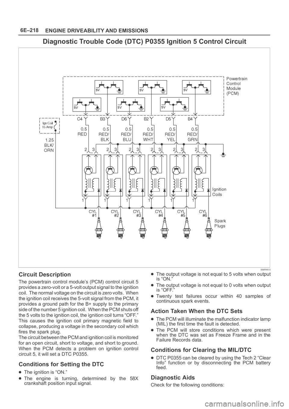
Diagnostic Trouble Code (DTC) P0355 Ignition 5 Control Circuit
D06RW072
Circuit Description
The powertrain control module’s (PCM) control circuit 5
provides a zero-volt or a 5-volt output signal to the ignition
coil. The normal voltage on the circuit is zero volts. When
the ignition coil receives the 5-volt signal from the PCM, it
provides a ground path for the B+ supply to the primary
side of the number 5 ignition coil. When the PCM shuts off
the 5 volts to the ignition coil, the ignition coil turns “OFF.”
This causes the ignition coil primary magnetic field to
collapse, producing a voltage in the secondary coil which
fires the spark plug.
The circuit between the PCM and ignition coil is monitored
for an open circuit, short to voltage, and short to ground.
When the PCM detects a problem on ignition control
circuit 5, it will set a DTC P0355.
Conditions for Setting the DTC
The ignition is “ON.”
The engine is turning, determined by the 58X
crankshaft position input signal.
The output voltage is not equal to 5 volts when output
is “ON.”
The output voltage is not equal to 0 volts when output
is “OFF.”
Twenty test failures occur within 40 samples of
continuous spark events.
Action Taken When the DTC Sets
The PCM will illuminate the malfunction indicator lamp
(MIL) the first time the fault is detected.
The PCM will store conditions which were present
when the DTC was set as Freeze Frame and in the
Failure Records data.
Conditions for Clearing the MIL/DTC
DTC P0355 can be cleared by using the Tech 2 “Clear
Info” function or by disconnecting the PCM battery
feed.
Diagnostic Aids
Check for the following conditions:
Page 4878 of 6000
6E–221 ENGINE DRIVEABILITY AND EMISSIONS
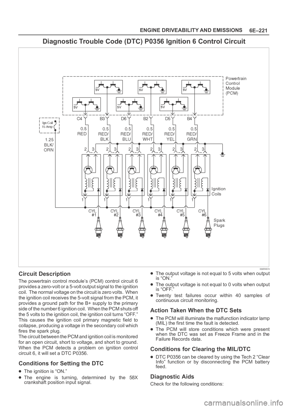
Diagnostic Trouble Code (DTC) P0356 Ignition 6 Control Circuit
D06RW072
Circuit Description
The powertrain control module’s (PCM) control circuit 6
provides a zero-volt or a 5-volt output signal to the ignition
coil. The normal voltage on the circuit is zero volts. When
the ignition coil receives the 5-volt signal from the PCM, it
provides a ground path for the B+ supply to the primary
side of the number 6 ignition coil. When the PCM shuts off
the 5 volts to the ignition coil, the ignition coil turns “OFF.”
This causes the ignition coil primary magnetic field to
collapse, producing a voltage in the secondary coil which
fires the spark plug.
The circuit between the PCM and ignition coil is monitored
for an open circuit, short to voltage, and short to ground.
When the PCM detects a problem on ignition control
circuit 6, it will set a DTC P0356.
Conditions for Setting the DTC
The ignition is “ON.”
The engine is turning, determined by the 58X
crankshaft position input signal.
The output voltage is not equal to 5 volts when output
is “ON.”
The output voltage is not equal to 0 volts when output
is “OFF.”
Twenty test failures occur within 40 samples of
continuous circuit monitoring.
Action Taken When the DTC Sets
The PCM will illuminate the malfunction indicator lamp
(MIL) the first time the fault is detected.
The PCM will store conditions which were present
when the DTC was set as Freeze Frame and in the
Failure Records data.
Conditions for Clearing the MIL/DTC
DTC P0356 can be cleared by using the Tech 2 “Clear
Info” function or by disconnecting the PCM battery
feed.
Diagnostic Aids
Check for the following conditions:
Page 4891 of 6000
6E–234
ENGINE DRIVEABILITY AND EMISSIONS
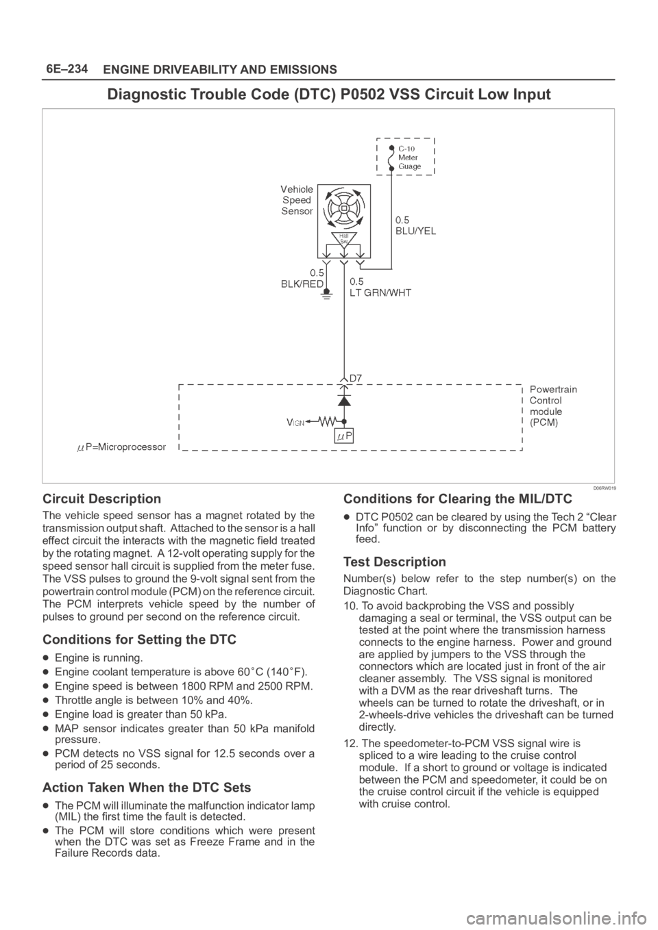
Diagnostic Trouble Code (DTC) P0502 VSS Circuit Low Input
D06RW019
Circuit Description
The vehicle speed sensor has a magnet rotated by the
transmission output shaft. Attached to the sensor is a hall
effect circuit the interacts with the magnetic field treated
by the rotating magnet. A 12-volt operating supply for the
speed sensor hall circuit is supplied from the meter fuse.
The VSS pulses to ground the 9-volt signal sent from the
powertrain control module (PCM) on the reference circuit.
The PCM interprets vehicle speed by the number of
pulses to ground per second on the reference circuit.
Conditions for Setting the DTC
Engine is running.
Engine coolant temperature is above 60C (140F).
Engine speed is between 1800 RPM and 2500 RPM.
Throttle angle is between 10% and 40%.
Engine load is greater than 50 kPa.
MAP sensor indicates greater than 50 kPa manifold
pressure.
PCM detects no VSS signal for 12.5 seconds over a
period of 25 seconds.
Action Taken When the DTC Sets
The PCM will illuminate the malfunction indicator lamp
(MIL) the first time the fault is detected.
The PCM will store conditions which were present
when the DTC was set as Freeze Frame and in the
Failure Records data.
Conditions for Clearing the MIL/DTC
DTC P0502 can be cleared by using the Tech 2 “Clear
Info” function or by disconnecting the PCM battery
feed.
Test Description
Number(s) below refer to the step number(s) on the
Diagnostic Chart.
10. To avoid backprobing the VSS and possibly
damaging a seal or terminal, the VSS output can be
tested at the point where the transmission harness
connects to the engine harness. Power and ground
are applied by jumpers to the VSS through the
connectors which are located just in front of the air
cleaner assembly. The VSS signal is monitored
with a DVM as the rear driveshaft turns. The
wheels can be turned to rotate the driveshaft, or in
2-wheels-drive vehicles the driveshaft can be turned
directly.
12. The speedometer-to-PCM VSS signal wire is
spliced to a wire leading to the cruise control
module. If a short to ground or voltage is indicated
between the PCM and speedometer, it could be on
the cruise control circuit if the vehicle is equipped
with cruise control.