Page 3555 of 6000
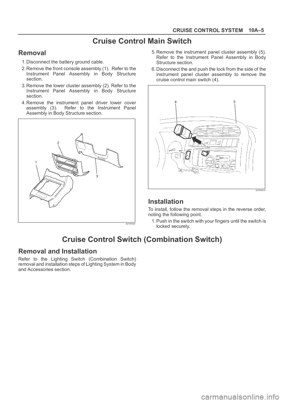
10A–4
CRUISE CONTROL SYSTEM
Starter Switch
Removal
1. Disconnect the battery ground cable.
2. Remove the front console assembly (1). Refer to the
Instrument Panel Assembly in Body Structure
section.
3. Remove the lower cluster assembly (2). Refer to the
Instrument Panel Assembly in Body Structure
section.
4. Remove the instrument panel driver lower cover
assembly (3). Refer to the Instrument Panel
Assembly in Body Structure section.
821RW024
5. Remove seven screws to remove the steering cowl
(6).
6. Disconnect the connector, remove the screw (4) and
then remove the starter switch (5).
431RW005
Installation
To install, follow the removal steps in the reverse order,
noting the following point.
1. When installing the steering cowl (10), be sure to pass
the harnesses through the route as shown in the
figure so that the starter switch harness (7), the
combination switch harness (8) and the inflator
module harness (9) will not catch.
825RW058
Page 3556 of 6000

10A–5
CRUISE CONTROL SYSTEM
Cruise Control Main Switch
Removal
1. Disconnect the battery ground cable.
2. Remove the front console assembly (1). Refer to the
Instrument Panel Assembly in Body Structure
section.
3. Remove the lower cluster assembly (2). Refer to the
Instrument Panel Assembly in Body Structure
section.
4. Remove the instrument panel driver lower cover
assembly (3). Refer to the Instrument Panel
Assembly in Body Structure section.
821RW024
5. Remove the instrument panel cluster assembly (5).
Refer to the Instrument Panel Assembly in Body
Structure section.
6. Disconnect the and push the lock from the side of the
instrument panel cluster assembly to remove the
cruise control main switch (4).
821RW079
Installation
To install, follow the removal steps in the reverse order,
noting the following point.
1. Push in the switch with your fingers until the switch is
locked securely.
Cruise Control Switch (Combination Switch)
Removal and Installation
Refer to the Lighting Switch (Combination Switch)
removal and installation steps of Lighting System in Body
and Accessories section.
Page 4047 of 6000
4B1–2
DRIVE LINE CONTROL SYSTEM (SHIFT ON THE FLY)
Shift on the Fly System (Lever Type)
Outline of Shift on the Fly System
(Lever Type)
The shift on the fly system (Lever type) switches between
2 wheel drive (2WD) and 4 wheel drive (4WD) by driver’s
shifting the transfer control lever on the floor.
This system controls below operations.
1. Connecting front wheels to, and disconnecting them
from, the front axles by vacuum actuator.
2. Indicator on instrument panel.
3. 4WD signal to Electronic Hydraulic Control Unit for
brake system (If anti–lock brake system is equipped).
Page 4052 of 6000
4B1–7 DRIVE LINE CONTROL SYSTEM (SHIFT ON THE FLY)
Shift on the Fly System (Push Button Type)
Outline of Shift on the Fly System (Push Button Type)
The shift on the fly system switches between 2 wheel
drive (2WD) and 4 wheel drive (4WD) electrically by
driver’s pressing the 4WD switch (push button type) on
instrument panel.
This system controls below operations. (Shifting between
“4H” and “4L” must be performed by transfer control lever
on the floor.)
1. Shifting the transfer front output gear (Connecting to,
and disconnecting from, front propeller shaft by motor
actuator).2. Retrial of shifting the transfer front output gear.
3. Connecting front wheels to, and disconnecting them
from, the front axles by vacuum actuator.
4. Indicator on instrument panel.
5. 4WD out signal to other Electronic Hydraulic Control
Unit (If anti–lock brake system is equipped).
System Diagrams
412RW050
Page 4053 of 6000
4B1–8
DRIVE LINE CONTROL SYSTEM (SHIFT ON THE FLY)
Normal Operation
The motor actuator mounted on transfer rear case is
driven by signal from 4WD switch on instrument panel.
After complete the connecting transfer front output gear
to, or disconnecting it from, front propeller shaft, conditionof the transfer position switch changes. The vacuum
solenoid valve (VSV) is driven by the signal from transfer
position switch and the vacuum actuator connects front
wheels to, or disconnect them from, front axles.
Time Chart of Shifting Under Normal Condition
F04RW002
Page 4054 of 6000

4B1–9 DRIVE LINE CONTROL SYSTEM (SHIFT ON THE FLY)
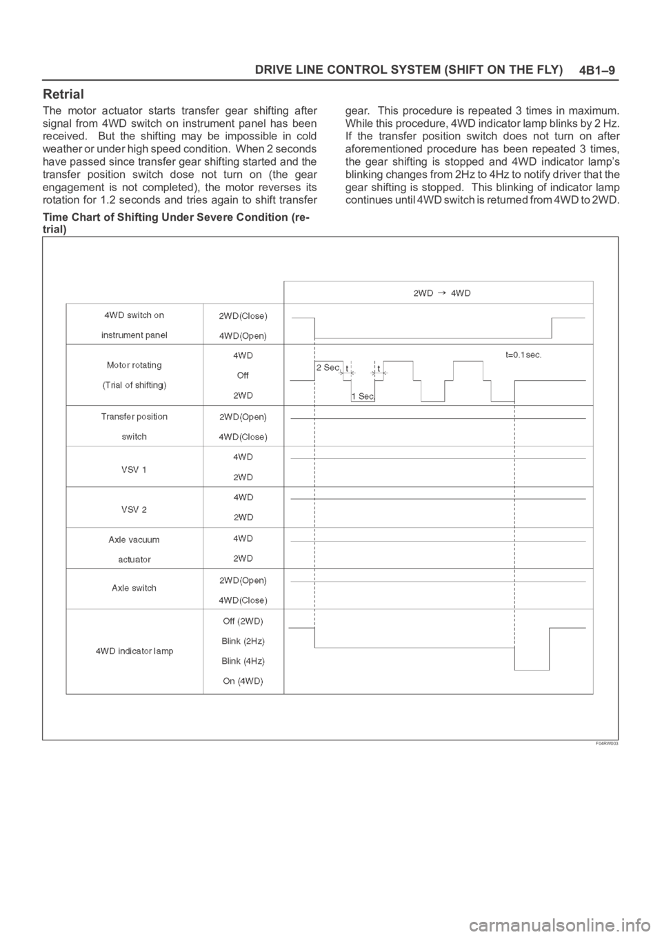
Retrial
The motor actuator starts transfer gear shifting after
signal from 4WD switch on instrument panel has been
received. But the shifting may be impossible in cold
weather or under high speed condition. When 2 seconds
have passed since transfer gear shifting started and the
transfer position switch dose not turn on (the gear
engagement is not completed), the motor reverses its
rotation for 1.2 seconds and tries again to shift transfergear. This procedure is repeated 3 times in maximum.
While this procedure, 4WD indicator lamp blinks by 2 Hz.
If the transfer position switch does not turn on after
aforementioned procedure has been repeated 3 times,
the gear shifting is stopped and 4WD indicator lamp’s
blinking changes from 2Hz to 4Hz to notify driver that the
gear shifting is stopped. This blinking of indicator lamp
continues until 4WD switch is returned from 4WD to 2WD.
Time Chart of Shifting Under Severe Condition (re-
trial)
F04RW003
Page 4086 of 6000

4B2–3 DRIVE LINE CONTROL SYSTEM (TOD)
condition, determines the optimum torque based on the
feedback control logic, and increases the torque to the
front wheels.
The control unit uses the signal from the throttle position
sensor to predict the future vehicle condition and the
intention of the driver with respect to acceleration and
deceleration, and determines the initial torque distribution
using these data and the information from the speed
sensors.
In case of small circle turning in the parking lot, for
example, the control unit minimizes the clutch pressing
force to restrict a braking phenomenon. When the ABS
becomes active, the control unit optimizes the clutch
pressing force to ensure stable braking.
TOD Indicator Control
The TOD indicator on the instrument panel informs the
driver of the current working status of the transfer unit.
The information consists of two items: the drive mode
(2H, TOD, 4L, transition) and the torque split status of the
TOD (torque distribution level). The indicator can display
occasional errors and corresponding error codes.
Page 4089 of 6000
DRIVE LINE CONTROL SYSTEM (TOD) 4B2–6
High-Low Planetary Gear Set
Establishes an auxiliary transmission mechanism. When
the transfer shift lever is set to the 2H or TOD position, the
reduction gear ratio is 1.000 and the corresponding
driving force is generated. When the transfer shift lever is
set to the 4L position, the reduction gear ratio is 2.480 and
the corresponding driving force is generated.
262RW030
4H and 4L Switch
Detects the shift position of the transfer from the
movement of the transfer lever and outputs signals to the
TOD control unit.
261RW002
Transfer Connector
Transmits the input and output signals of the speed
sensors, electromagnetic coil, and 4H and 4L switche to
the vehicle harness. A waterproof 12-pin type is used.
261RW046
TOD Indicator Lamps (on the instrument
panel)
Inform the following items.
Bulb check
Drive mode
ABS IN status
BRAKE ON status
821RW049