Page 4735 of 6000

6E–78
ENGINE DRIVEABILITY AND EMISSIONS
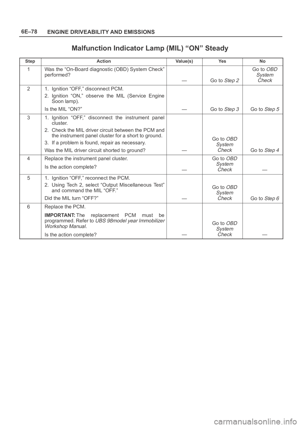
Malfunction Indicator Lamp (MIL) “ON” Steady
StepActionVa l u e ( s )Ye sNo
1Was the “On-Board diagnostic (OBD) System Check”
performed?
—Go to Step 2
Go to OBD
System
Check
21. Ignition “OFF,” disconnect PCM.
2. Ignition “ON,” observe the MIL (Service Engine
Soon lamp).
Is the MIL “ON?”
—Go to Step 3Go to Step 5
31. Ignition “OFF,” disconnect the instrument panel
cluster.
2. Check the MIL driver circuit between the PCM and
the instrument panel cluster for a short to ground.
3. If a problem is found, repair as necessary.
Was the MIL driver circuit shorted to ground?
—
Go to OBD
System
Check
Go to Step 4
4Replace the instrument panel cluster.
Is the action complete?
—
Go to OBD
System
Check
—
51. Ignition “OFF,” reconnect the PCM.
2. Using Tech 2, select “Output Miscellaneous Test”
and command the MIL “OFF.”
Did the MIL turn “OFF?”
—
Go to OBD
System
Check
Go to Step 6
6Replace the PCM.
IMPORTANT:The replacement PCM must be
programmed. Refer to
UBS 98model year Immobilizer
Workshop Manual.
Is the action complete?—
Go to OBD
System
Check
—
Page 5456 of 6000

6E–27 4JX1–TC ENGINE DRIVEABILITY AND EMISSIONS
Non-Emissions related
Dose not request illumination of any lamp
Stores a History DTC on the first trip with a fail
Stores Fail Record when test fails
Updates the Fail Record each time the diagnostic test
fails
Storing and Erasing Freeze Frame Data and Failure
Records
The data captured is called Freeze Frame data. The
Freeze Frame data is very similar to a single record of
operating conditions. Whenever the MIL is illuminated,
the corresponding record of operating conditions is
recorded to the Freeze Frame buffer.
Data from these faults take precedence over data
associated with any other fault. The Freeze Frame data
will not be erased unless the associated history DTC is
cleared.
Each time a diagnostic test reports a failure, the current
engine operating conditions are recorded in the
Failure
Records
buffer. A subsequent failure will update the
recorded operating conditions. The following operating
conditions for the diagnostic test which failed
typically
include the following parameters:
Engine Speed
Engine Load
Engine Coolant Temperature
Vehicle Speed
Intake Throttle Position
MAP
Injector Base Pulse Width
Loop Status
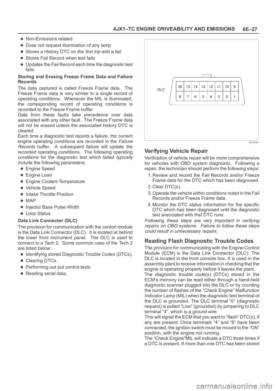
Data Link Connector (DLC)
The provision for communication with the contorl module
is the Data Link Connector (DLC). It is located at behind
the lower front instrument panel. The DLC is used to
connect to a Tech 2. Some common uses of the Tech 2
are listed below:
Identifying stored Diagnostic Trouble Codes (DTCs).
Clearing DTCs.
Performing out put control tests.
Reading serial data.
060RW046
Verifying Vehicle Repair
Verification of vehicle repair will be more comprehensive
for vehicles with OBD system diagnostic. Following a
repair, the technician should perform the following steps:
1. Review and record the Fail Records and/or Freeze
Frame data for the DTC which has been diagnosed.
2. Clear DTC(s).
3. Operate the vehicle within conditions noted in the Fail
Records and/or Freeze Frame data.
4. Monitor the DTC status information for the specific
DTC which has been diagnosed until the diagnostic
test associated with that DTC runs.
Following these steps are very important in verifying
repairs on OBD systems. Failure to follow these steps
could result in unnecessary repairs.
Reading Flash Diagnostic Trouble Codes
The provision for communicating with the Engine Control
Module (ECM) is the Data Link Connector (DLC). The
DLC is located in the front console box. It is used in the
assembly plant to receive information in checking that the
engine is operating properly before it leaves the plant.
The diagnostic trouble code(s) (DTCs) stored in the
ECM’s memory can be read either through a hand-held
diagnostic scanner plugged into the DLC or by counting
the number of flashes of the “Check Engine” Malfunction
Indicator Lamp (MIL) when the diagnostic test terminal of
the DLC is grounded. The DLC terminal “6” (diagnostic
request) is pulled “Low” (grounded) by jumpering to DLC
terminal “4”, which is a ground wire.
This will signal the ECM that you want to “flash” DTC(s), if
any are present. Once terminals “4” and “6” have been
connected, the ignition switch must be moved to the “ON”
position, with the engine not running.
The “Check Engine”MIL will indicate a DTC three times if
a DTC is present. If more than one DTC has been stored
Page 5475 of 6000
6E–46
4JX1–TC ENGINE DRIVEABILITY AND EMISSIONS
No Malfunction Indicator Lamp (MIL)
StepNo Ye s Va l u e ( s ) Action
15Locate and repair the short to ground in the ECM
ignition feed circuit or ECM battery feed circuit.
Is the action complete?
—Verify repair—
16Locate and repair the short to ground in the ignition
feed circuit to the instrument cluster, and replace the
fuse.
Is the action complete?
—Verify repair—
17Replace the ECM (Refer to the Data Programming in
Case of ECM change).
Is the action complete?
—Verify repair—
18Check the MIL driver circuit for a poor connection at the
instrument panel connector.
Was a problem found?
—Verify repair
Go to
Instrument
Panel
in
Electrical
Diagnosis
Page 5476 of 6000

6E–47 4JX1–TC ENGINE DRIVEABILITY AND EMISSIONS
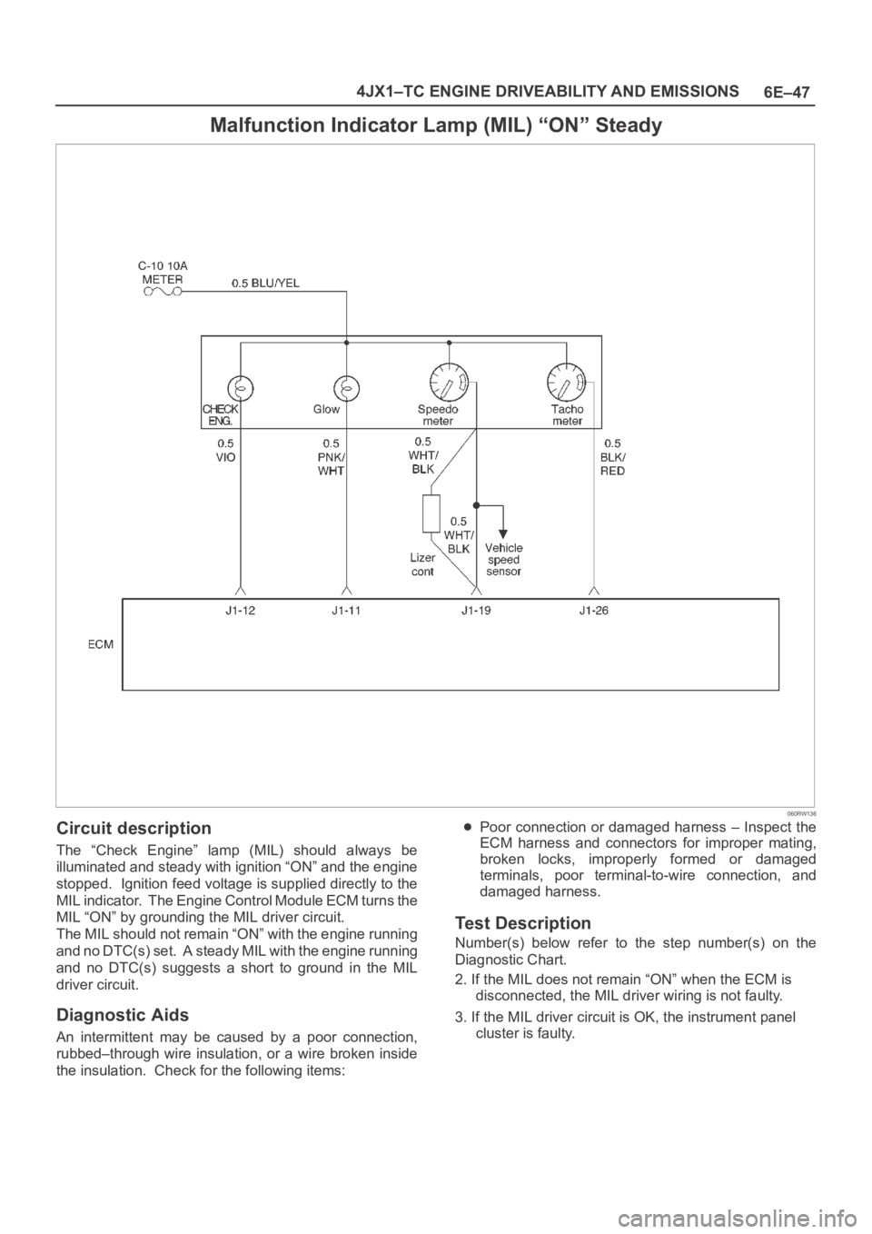
Malfunction Indicator Lamp (MIL) “ON” Steady
060RW136
Circuit description
The “Check Engine” lamp (MIL) should always be
illuminated and steady with ignition “ON” and the engine
stopped. Ignition feed voltage is supplied directly to the
MIL indicator. The Engine Control Module ECM turns the
MIL “ON” by grounding the MIL driver circuit.
The MIL should not remain “ON” with the engine running
and no DTC(s) set. A steady MIL with the engine running
and no DTC(s) suggests a short to ground in the MIL
driver circuit.
Diagnostic Aids
An intermittent may be caused by a poor connection,
rubbed–through wire insulation, or a wire broken inside
the insulation. Check for the following items:
Poor connection or damaged harness – Inspect the
ECM harness and connectors for improper mating,
broken locks, improperly formed or damaged
terminals, poor terminal-to-wire connection, and
damaged harness.
Test Description
Number(s) below refer to the step number(s) on the
Diagnostic Chart.
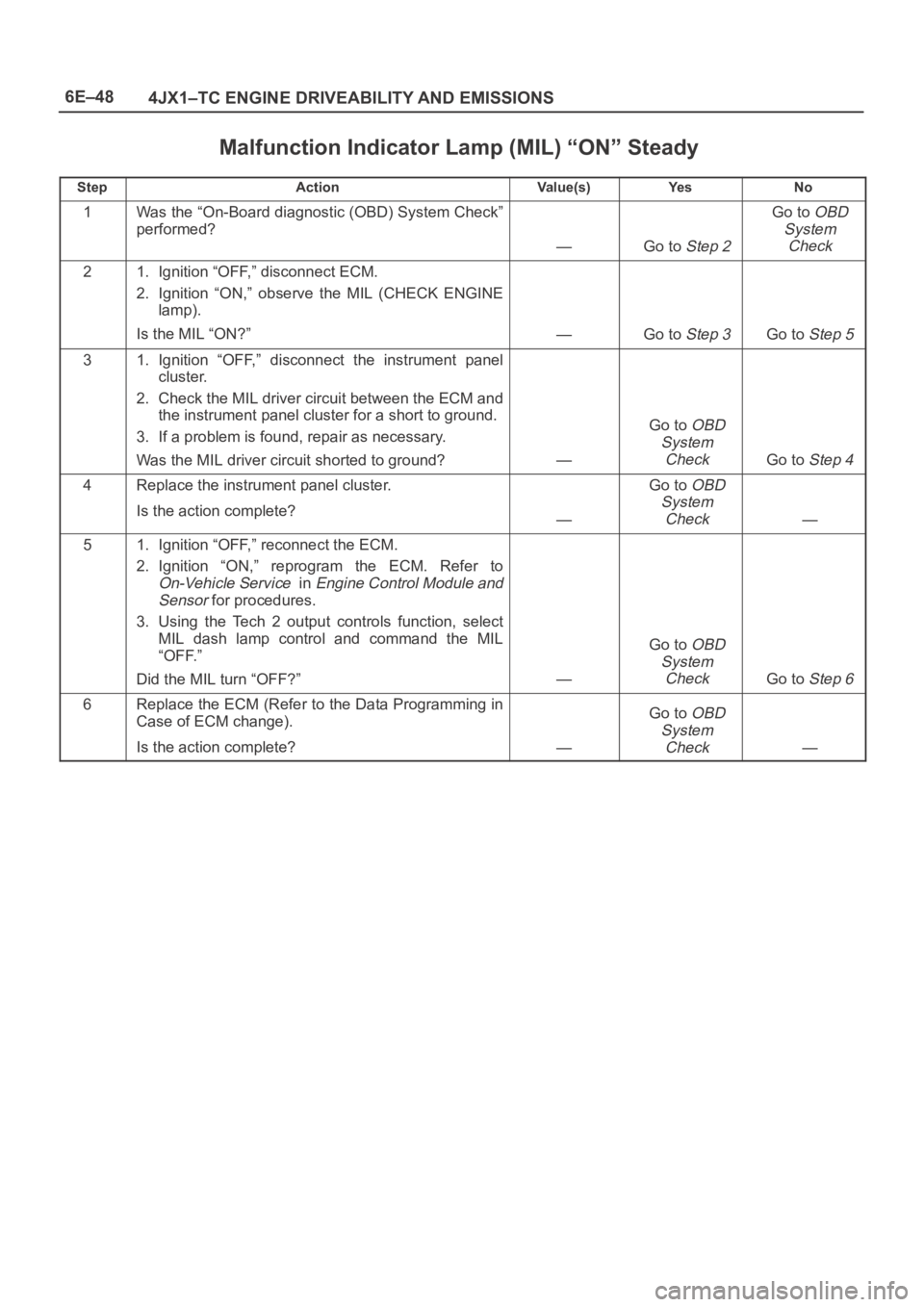
2. If the MIL does not remain “ON” when the ECM is
disconnected, the MIL driver wiring is not faulty.
3. If the MIL driver circuit is OK, the instrument panel
cluster is faulty.
Page 5477 of 6000

6E–48
4JX1–TC ENGINE DRIVEABILITY AND EMISSIONS
Malfunction Indicator Lamp (MIL) “ON” Steady
StepActionVa l u e ( s )Ye sNo
1Was the “On-Board diagnostic (OBD) System Check”
performed?
—Go to Step 2
Go to OBD
System
Check
21. Ignition “OFF,” disconnect ECM.
2. Ignition “ON,” observe the MIL (CHECK ENGINE
lamp).
Is the MIL “ON?”
—Go to Step 3Go to Step 5
31. Ignition “OFF,” disconnect the instrument panel
cluster.
2. Check the MIL driver circuit between the ECM and
the instrument panel cluster for a short to ground.
3. If a problem is found, repair as necessary.
Was the MIL driver circuit shorted to ground?
—
Go to OBD
System
Check
Go to Step 4
4Replace the instrument panel cluster.
Is the action complete?
—
Go to OBD
System
Check
—
51. Ignition “OFF,” reconnect the ECM.
2. Ignition “ON,” reprogram the ECM. Refer to
On-Vehicle Service in Engine Control Module and
Sensor
for procedures.
3. Using the Tech 2 output controls function, select
MIL dash lamp control and command the MIL
“OFF.”
Did the MIL turn “OFF?”
—
Go to OBD
System
Check
Go to Step 6
6Replace the ECM (Refer to the Data Programming in
Case of ECM change).
Is the action complete?
—
Go to OBD
System
Check
—