1998 OPEL FRONTERA Instrument panel
[x] Cancel search: Instrument panelPage 4304 of 6000
TRANSFER CASE (STANDARD TYPE)
4D1–43
Main Data and Specifications
General Specifications
Ty p eW/Shift On The Fly System model
Synchronized type gears shifting between the 2 and 4 wheel drive mode.
Constant mesh type gears shifting between “low” and “high”.
WO/Shift On The Fly System model
Constant mesh type gears shifting between the 2 and 4 wheel drive mode,
and between “low” and “high”.
Control methodW/4WD Switch model
Electric control with the button switch on the instrument panel for gear
shifting between the 2 and 4 wheel drive mode.
Remote control with the gear shift lever on the floor for gear shifting
between “low and high” .
WO/4WD Switch model
Remote control with the gear shift lever on the floor for gear shifting.
Gear ratioHigh; 1.000
Low; 2.050
Oil capacity1.45 lit. (1.53 U.S. quart)
Type of lubricantEngine oil
Refer to chart in Section 0
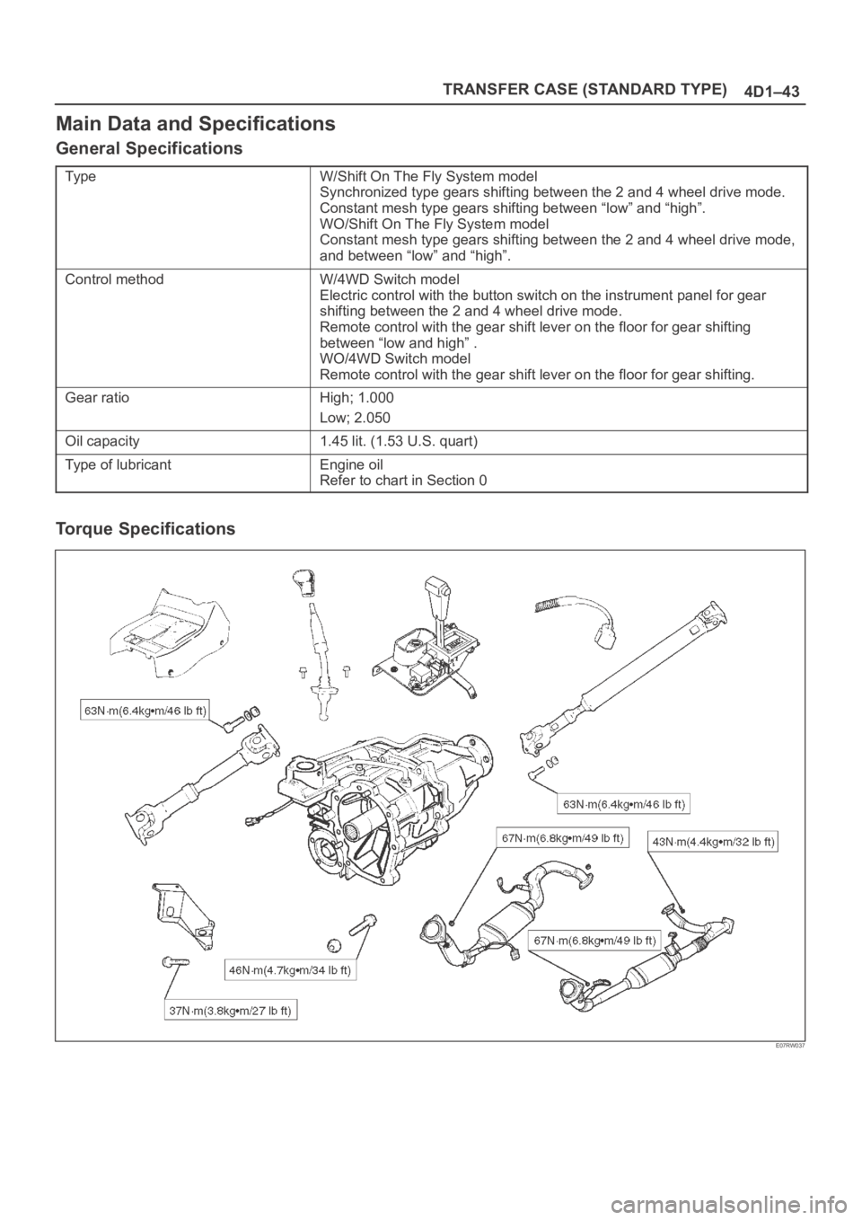
Torque Specifications
E07RW037
Page 4354 of 6000
5A–4
BRAKE CONTROL SYSTEM
normal braking when a malfunction has occurred in the
ABS.
The EHCU has a self-diagnosing function which can
indicate faulty circuits during diagnosis.
The EHCU is mounted on the engine compartment front
right side. It consists of a Motor, Plunger Pump, Solenoid
Valves and Check Valve.
On the outside, the relay box containing a motor relay and
a valve relay is installed.
Solenoid Valves: Reduces or holds the caliper fluid
pressure for each front disc brake or both rear disc brakes
according to the signal sent from the EHCU.
Reservoir: Temporarily holds the brake fluid that returns
from the front and rear disc brake caliper so that pressure
of front disc brake caliper can be reduced smoothly.
Plunger Pump: Feeds the brake fluid held in the reservoir
to the master cylinder.
Motor: Drives the pump according to the signal from
EHCU.
Check Valve: Controls the brake fluid flow.
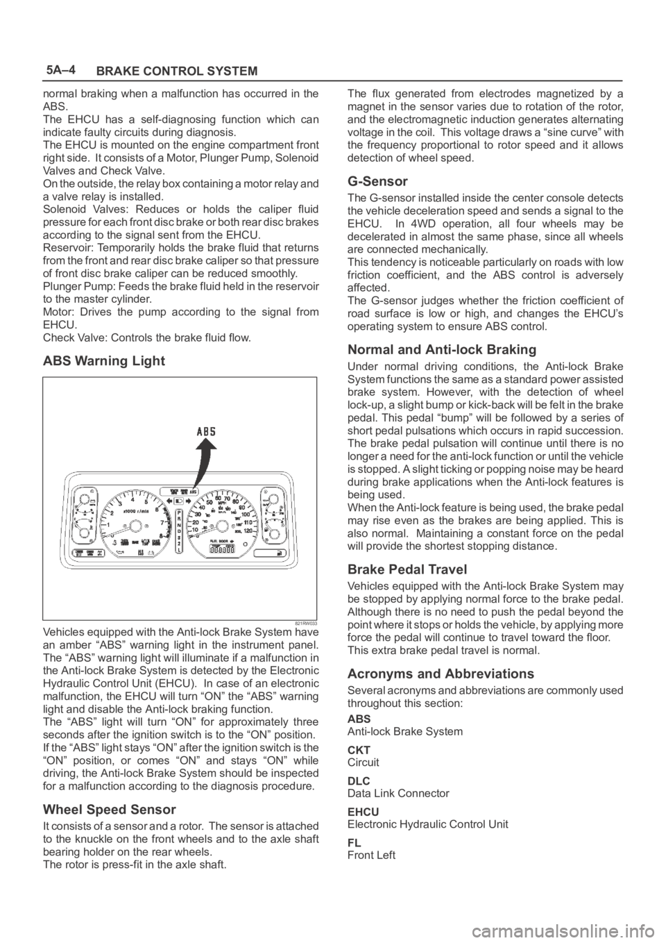
ABS Warning Light
821RW033Vehicles equipped with the Anti-lock Brake System have
an amber “ABS” warning light in the instrument panel.
The “ABS” warning light will illuminate if a malfunction in
the Anti-lock Brake System is detected by the Electronic
Hydraulic Control Unit (EHCU). In case of an electronic
malfunction, the EHCU will turn “ON” the “ABS” warning
light and disable the Anti-lock braking function.
The “ABS” light will turn “ON” for approximately three
seconds after the ignition switch is to the “ON” position.
If the “ABS” light stays “ON” after the ignition switch is the
“ON” position, or comes “ON” and stays “ON” while
driving, the Anti-lock Brake System should be inspected
for a malfunction according to the diagnosis procedure.
Wheel Speed Sensor
It consists of a sensor and a rotor. The sensor is attached
to the knuckle on the front wheels and to the axle shaft
bearing holder on the rear wheels.
The rotor is press-fit in the axle shaft.The flux generated from electrodes magnetized by a
magnet in the sensor varies due to rotation of the rotor,
and the electromagnetic induction generates alternating
voltage in the coil. This voltage draws a “sine curve” with
the frequency proportional to rotor speed and it allows
detection of wheel speed.
G-Sensor
The G-sensor installed inside the center console detects
the vehicle deceleration speed and sends a signal to the
EHCU. In 4WD operation, all four wheels may be
decelerated in almost the same phase, since all wheels
are connected mechanically.
This tendency is noticeable particularly on roads with low
friction coefficient, and the ABS control is adversely
affected.
The G-sensor judges whether the friction coefficient of
road surface is low or high, and changes the EHCU’s
operating system to ensure ABS control.
Normal and Anti-lock Braking
Under normal driving conditions, the Anti-lock Brake
System functions the same as a standard power assisted
brake system. However, with the detection of wheel
lock-up, a slight bump or kick-back will be felt in the brake
pedal. This pedal “bump” will be followed by a series of
short pedal pulsations which occurs in rapid succession.
The brake pedal pulsation will continue until there is no
longer a need for the anti-lock function or until the vehicle
is stopped. A slight ticking or popping noise may be heard
during brake applications when the Anti-lock features is
being used.
When the Anti-lock feature is being used, the brake pedal
may rise even as the brakes are being applied. This is
also normal. Maintaining a constant force on the pedal
will provide the shortest stopping distance.
Brake Pedal Travel
Vehicles equipped with the Anti-lock Brake System may
be stopped by applying normal force to the brake pedal.
Although there is no need to push the pedal beyond the
point where it stops or holds the vehicle, by applying more
force the pedal will continue to travel toward the floor.
This extra brake pedal travel is normal.
Acronyms and Abbreviations
Several acronyms and abbreviations are commonly used
throughout this section:
ABS
Anti-lock Brake System
CKT
Circuit
DLC
Data Link Connector
EHCU
Electronic Hydraulic Control Unit
FL
Front Left
Page 4513 of 6000
6A–17
ENGINE MECHANICAL
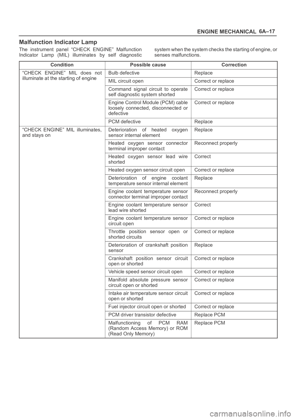
Malfunction Indicator Lamp
The instrument panel “CHECK ENGINE” Malfunction
Indicator Lamp (MIL) illuminates by self diagnosticsystem when the system checks the starting of engine, or
senses malfunctions.
Condition
Possible causeCorrection
“CHECK ENGINE” MIL does not
illuminate at the starting of engine
Bulb defectiveReplace
illuminate at the starting of engineMIL circuit openCorrect or replace
Command signal circuit to operate
self diagnostic system shortedCorrect or replace
Engine Control Module (PCM) cable
loosely connected, disconnected or
defectiveCorrect or replace
PCM defectiveReplace
“CHECK ENGINE” MIL illuminates,
and stays onDeterioration of heated oxygen
sensor internal elementReplace
Heated oxygen sensor connector
terminal improper contactReconnect properly
Heated oxygen sensor lead wire
shortedCorrect
Heated oxygen sensor circuit openCorrect or replace
Deterioration of engine coolant
temperature sensor internal elementReplace
Engine coolant temperature sensor
connector terminal improper contactReconnect properly
Engine coolant temperature sensor
lead wire shortedCorrect
Engine coolant temperature sensor
circuit openCorrect or replace
Throttle position sensor open or
shorted circuitsCorrect or replace
Deterioration of crankshaft position
sensorReplace
Crankshaft position sensor circuit
open or shortedCorrect or replace
Vehicle speed sensor circuit openCorrect or replace
Manifold absolute pressure sensor
circuit open or shortedCorrect or replace
Intake air temperature sensor circuit
open or shortedCorrect or replace
Fuel injector circuit open or shortedCorrect or replace
PCM driver transistor defectiveReplace PCM
Malfunctioning of PCM RAM
(Random Access Memory) or ROM
(Read Only Memory)Replace PCM
Page 4686 of 6000
6E–29 ENGINE DRIVEABILITY AND EMISSIONS
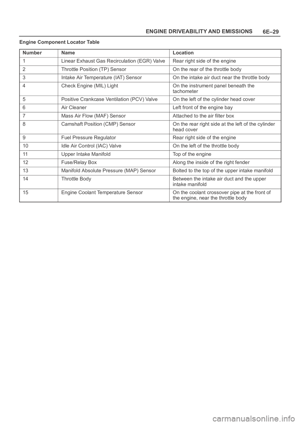
Engine Component Locator Table
Number
NameLocation
1Linear Exhaust Gas Recirculation (EGR) ValveRear right side of the engine
2Throttle Position (TP) SensorOn the rear of the throttle body
3Intake Air Temperature (IAT) SensorOn the intake air duct near the throttle body
4Check Engine (MIL) LightOn the instrument panel beneath the
tachometer
5Positive Crankcase Ventilation (PCV) ValveOn the left of the cylinder head cover
6Air CleanerLeft front of the engine bay
7Mass Air Flow (MAF) SensorAttached to the air filter box
8Camshaft Position (CMP) SensorOn the rear right side at the left of the cylinder
head cover
9Fuel Pressure RegulatorRear right side of the engine
10Idle Air Control (IAC) ValveOn the left of the throttle body
11Upper Intake ManifoldTop of the engine
12Fuse/Relay BoxAlong the inside of the right fender
13Manifold Absolute Pressure (MAP) SensorBolted to the top of the upper intake manifold
14Throttle BodyBetween the intake air duct and the upper
intake manifold
15Engine Coolant Temperature SensorOn the coolant crossover pipe at the front of
the engine, near the throttle body
Page 4688 of 6000
6E–31 ENGINE DRIVEABILITY AND EMISSIONS
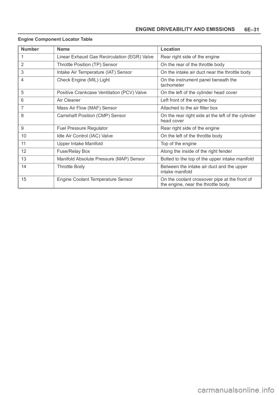
Engine Component Locator Table
Number
NameLocation
1Linear Exhaust Gas Recirculation (EGR) ValveRear right side of the engine
2Throttle Position (TP) SensorOn the rear of the throttle body
3Intake Air Temperature (IAT) SensorOn the intake air duct near the throttle body
4Check Engine (MIL) LightOn the instrument panel beneath the
tachometer
5Positive Crankcase Ventilation (PCV) ValveOn the left of the cylinder head cover
6Air CleanerLeft front of the engine bay
7Mass Air Flow (MAF) SensorAttached to the air filter box
8Camshaft Position (CMP) SensorOn the rear right side at the left of the cylinder
head cover
9Fuel Pressure RegulatorRear right side of the engine
10Idle Air Control (IAC) ValveOn the left of the throttle body
11Upper Intake ManifoldTop of the engine
12Fuse/Relay BoxAlong the inside of the right fender
13Manifold Absolute Pressure (MAP) SensorBolted to the top of the upper intake manifold
14Throttle BodyBetween the intake air duct and the upper
intake manifold
15Engine Coolant Temperature SensorOn the coolant crossover pipe at the front of
the engine, near the throttle body
Page 4698 of 6000
6E–41 ENGINE DRIVEABILITY AND EMISSIONS
If the MIL was set by either a fuel trim or misfire-related
DTC, additional requirements must be met. In addition to
the requirements stated in the previous paragraph, these
requirements are as follows:
The diagnostic tests that are passed must occur with
375 RPM of the RPM data stored at the time the last
test failed.
Plus or minus ten (10) percent of the engine load that
was stored at the time the last failed.
Similar engine temperature conditions (warmed up or
warming up ) as those stored at the time the last test
failed.
Meeting these requirements ensures that the fault which
turned on the MIL has been corrected.
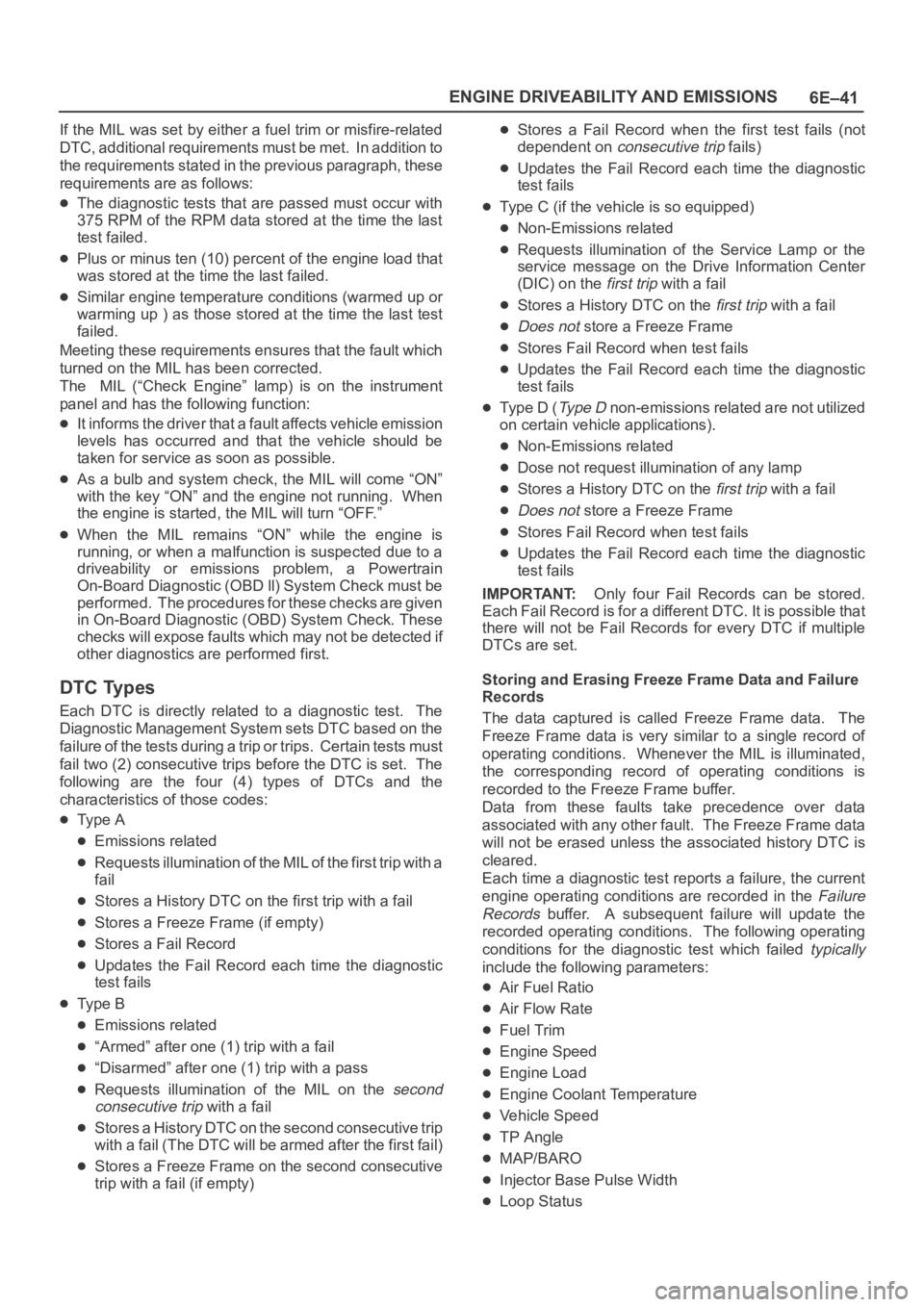
The MIL (“Check Engine” lamp) is on the instrument
panel and has the following function:
It informs the driver that a fault affects vehicle emission
levels has occurred and that the vehicle should be
taken for service as soon as possible.
As a bulb and system check, the MIL will come “ON”
with the key “ON” and the engine not running. When
the engine is started, the MIL will turn “OFF.”
When the MIL remains “ON” while the engine is
running, or when a malfunction is suspected due to a
driveability or emissions problem, a Powertrain
On-Board Diagnostic (OBD ll) System Check must be
performed. The procedures for these checks are given
in On-Board Diagnostic (OBD) System Check. These
checks will expose faults which may not be detected if
other diagnostics are performed first.
DTC Types
Each DTC is directly related to a diagnostic test. The
Diagnostic Management System sets DTC based on the
failure of the tests during a trip or trips. Certain tests must
fail two (2) consecutive trips before the DTC is set. The
following are the four (4) types of DTCs and the
characteristics of those codes:
Ty p e A
Emissions related
Requests illumination of the MIL of the first trip with a
fail
Stores a History DTC on the first trip with a fail
Stores a Freeze Frame (if empty)
Stores a Fail Record
Updates the Fail Record each time the diagnostic
test fails
Ty p e B
Emissions related
“Armed” after one (1) trip with a fail
“Disarmed” after one (1) trip with a pass
Requests illumination of the MIL on the second
consecutive trip
with a fail
Stores a History DTC on the second consecutive trip
with a fail (The DTC will be armed after the first fail)
Stores a Freeze Frame on the second consecutive
trip with a fail (if empty)
Stores a Fail Record when the first test fails (not
dependent on
consecutive trip fails)
Updates the Fail Record each time the diagnostic
test fails
Type C (if the vehicle is so equipped)
Non-Emissions related
Requests illumination of the Service Lamp or the
service message on the Drive Information Center
(DIC) on the
first trip with a fail
Stores a History DTC on the first trip with a fail
Does not store a Freeze Frame
Stores Fail Record when test fails
Updates the Fail Record each time the diagnostic
test fails
Type D (Ty p e D non-emissions related are not utilized
on certain vehicle applications).
Non-Emissions related
Dose not request illumination of any lamp
Stores a History DTC on the first trip with a fail
Does not store a Freeze Frame
Stores Fail Record when test fails
Updates the Fail Record each time the diagnostic
test fails
IMPORTANT:Only four Fail Records can be stored.
Each Fail Record is for a different DTC. It is possible that
there will not be Fail Records for every DTC if multiple
DTCs are set.
Storing and Erasing Freeze Frame Data and Failure
Records
The data captured is called Freeze Frame data. The
Freeze Frame data is very similar to a single record of
operating conditions. Whenever the MIL is illuminated,
the corresponding record of operating conditions is
recorded to the Freeze Frame buffer.
Data from these faults take precedence over data
associated with any other fault. The Freeze Frame data
will not be erased unless the associated history DTC is
cleared.
Each time a diagnostic test reports a failure, the current
engine operating conditions are recorded in the
Failure
Records
buffer. A subsequent failure will update the
recorded operating conditions. The following operating
conditions for the diagnostic test which failed
typically
include the following parameters:
Air Fuel Ratio
Air Flow Rate
Fuel Trim
Engine Speed
Engine Load
Engine Coolant Temperature
Vehicle Speed
TP Angle
MAP/BARO
Injector Base Pulse Width
Loop Status
Page 4733 of 6000
6E–76
ENGINE DRIVEABILITY AND EMISSIONS
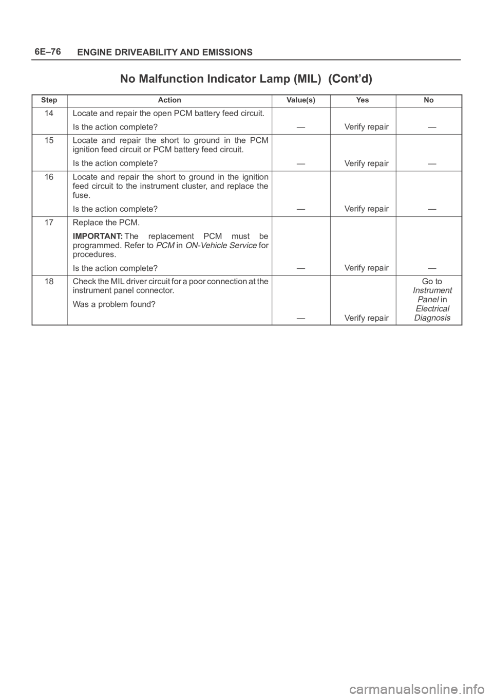
No Malfunction Indicator Lamp (MIL)
StepNo Ye s Va l u e ( s ) Action
14Locate and repair the open PCM battery feed circuit.
Is the action complete?
—Verify repair—
15Locate and repair the short to ground in the PCM
ignition feed circuit or PCM battery feed circuit.
Is the action complete?
—Verify repair—
16Locate and repair the short to ground in the ignition
feed circuit to the instrument cluster, and replace the
fuse.
Is the action complete?
—Verify repair—
17Replace the PCM.
IMPORTANT:The replacement PCM must be
programmed. Refer to
PCM in ON-Vehicle Service for
procedures.
Is the action complete?
—Verify repair—
18Check the MIL driver circuit for a poor connection at the
instrument panel connector.
Was a problem found?
—Verify repair
Go to
Instrument
Panel
in
Electrical
Diagnosis
Page 4734 of 6000
6E–77 ENGINE DRIVEABILITY AND EMISSIONS
Malfunction Indicator Lamp (MIL) “ON” Steady
D06RW00007
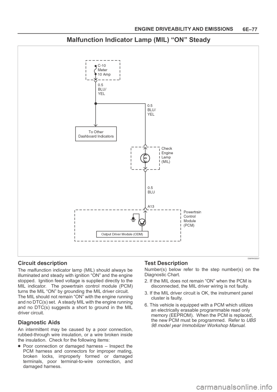
Circuit description
The malfunction indicator lamp (MIL) should always be
illuminated and steady with ignition “ON” and the engine
stopped. Ignition feed voltage is supplied directly to the
MIL indicator. The powertrain control module (PCM)
turns the MIL “ON” by grounding the MIL driver circuit.
The MIL should not remain “ON” with the engine running
and no DTC(s) set. A steady MIL with the engine running
and no DTC(s) suggests a short to ground in the MIL
driver circuit.
Diagnostic Aids
An intermittent may be caused by a poor connection,
rubbed-through wire insulation, or a wire broken inside
the insulation. Check for the following items:
Poor connection or damaged harness – Inspect the
PCM harness and connectors for improper mating,
broken locks, improperly formed or damaged
terminals, poor terminal-to-wire connection, and
damaged harness.
Test Description
Number(s) below refer to the step number(s) on the
Diagnostic Chart.
2. If the MIL does not remain “ON” when the PCM is
disconnected, the MIL driver wiring is not faulty.
3. If the MIL driver circuit is OK, the instrument panel
cluster is faulty.
6. This vehicle is equipped with a PCM which utilizes
an electrically erasable programmable read only
memory (EEPROM). When the PCM is replaced,
the new PCM must be programmed. Refer to
UBS
98 model year Immobilizer Workshop Manual.