1998 OPEL FRONTERA battery
[x] Cancel search: batteryPage 4175 of 6000
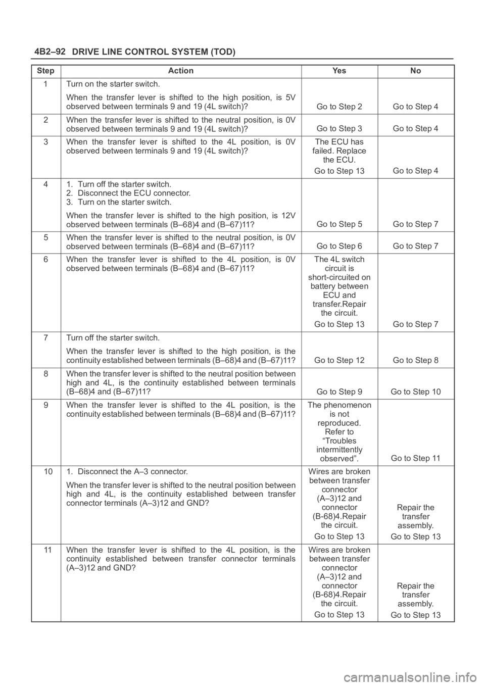
DRIVE LINE CONTROL SYSTEM (TOD) 4B2–92
StepActionYe sNo
1Turn on the starter switch.
When the transfer lever is shifted to the high position, is 5V
observed between terminals 9 and 19 (4L switch)?
Go to Step 2Go to Step 4
2When the transfer lever is shifted to the neutral position, is 0V
observed between terminals 9 and 19 (4L switch)?
Go to Step 3Go to Step 4
3When the transfer lever is shifted to the 4L position, is 0V
observed between terminals 9 and 19 (4L switch)?The ECU has
failed. Replace
the ECU.
Go to Step 13
Go to Step 4
41. Turn off the starter switch.
2. Disconnect the ECU connector.
3. Turn on the starter switch.
When the transfer lever is shifted to the high position, is 12V
observed between terminals (B–68)4 and (B–67)11?
Go to Step 5Go to Step 7
5When the transfer lever is shifted to the neutral position, is 0V
observed between terminals (B–68)4 and (B–67)11?
Go to Step 6Go to Step 7
6When the transfer lever is shifted to the 4L position, is 0V
observed between terminals (B–68)4 and (B–67)11?The 4L switch
circuit is
short-circuited on
battery between
ECU and
transfer.Repair
the circuit.
Go to Step 13
Go to Step 7
7Turn off the starter switch.
When the transfer lever is shifted to the high position, is the
continuity established between terminals (B–68)4 and (B–67)11?
Go to Step 12Go to Step 8
8When the transfer lever is shifted to the neutral position between
high and 4L, is the continuity established between terminals
(B–68)4 and (B–67)11?
Go to Step 9Go to Step 10
9When the transfer lever is shifted to the 4L position, is the
continuity established between terminals (B–68)4 and (B–67)11?The phenomenon
is not
reproduced.
Refer to
“Troubles
intermittently
observed”.
Go to Step 11
101. Disconnect the A–3 connector.
When the transfer lever is shifted to the neutral position between
high and 4L, is the continuity established between transfer
connector terminals (A–3)12 and GND?Wires are broken
between transfer
connector
(A–3)12 and
connector
(B-68)4.Repair
the circuit.
Go to Step 13
Repair the
transfer
assembly.
Go to Step 13
11When the transfer lever is shifted to the 4L position, is the
continuity established between transfer connector terminals
(A–3)12 and GND?Wires are broken
between transfer
connector
(A–3)12 and
connector
(B-68)4.Repair
the circuit.
Go to Step 13
Repair the
transfer
assembly.
Go to Step 13
Page 4185 of 6000
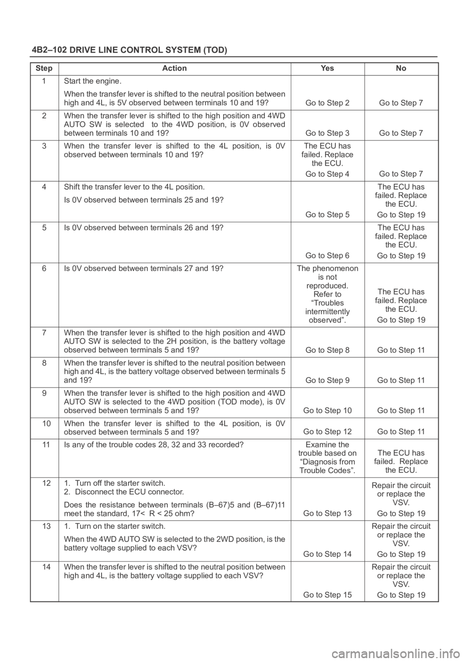
DRIVE LINE CONTROL SYSTEM (TOD) 4B2–102
StepActionYe sNo
1Start the engine.
When the transfer lever is shifted to the neutral position between
high and 4L, is 5V observed between terminals 10 and 19?
Go to Step 2Go to Step 7
2When the transfer lever is shifted to the high position and 4WD
AUTO SW is selected to the 4WD position, is 0V observed
between terminals 10 and 19?
Go to Step 3Go to Step 7
3When the transfer lever is shifted to the 4L position, is 0V
observed between terminals 10 and 19?The ECU has
failed. Replace
the ECU.
Go to Step 4
Go to Step 7
4Shift the transfer lever to the 4L position.
Is 0V observed between terminals 25 and 19?
Go to Step 5
The ECU has
failed. Replace
the ECU.
Go to Step 19
5Is 0V observed between terminals 26 and 19?
Go to Step 6
The ECU has
failed. Replace
the ECU.
Go to Step 19
6Is 0V observed between terminals 27 and 19?The phenomenon
is not
reproduced.
Refer to
“Troubles
intermittently
observed”.
The ECU has
failed. Replace
the ECU.
Go to Step 19
7When the transfer lever is shifted to the high position and 4WD
AUTO SW is selected to the 2H position, is the battery voltage
observed between terminals 5 and 19?
Go to Step 8Go to Step 11
8When the transfer lever is shifted to the neutral position between
high and 4L, is the battery voltage observed between terminals 5
and 19?
Go to Step 9Go to Step 11
9When the transfer lever is shifted to the high position and 4WD
AUTO SW is selected to the 4WD position (TOD mode), is 0V
observed between terminals 5 and 19?
Go to Step 10Go to Step 11
10When the transfer lever is shifted to the 4L position, is 0V
observed between terminals 5 and 19?
Go to Step 12Go to Step 11
11Is any of the trouble codes 28, 32 and 33 recorded?Examine the
trouble based on
“Diagnosis from
Trouble Codes”.
The ECU has
failed. Replace
the ECU.
121. Turn off the starter switch.
2. Disconnect the ECU connector.
Does the resistance between terminals (B–67)5 and (B–67)11
meet the standard, 17< R < 25 ohm?
Go to Step 13
Repair the circuit
or replace the
VSV.
Go to Step 19
131. Turn on the starter switch.
When the 4WD AUTO SW is selected to the 2WD position, is the
battery voltage supplied to each VSV?
Go to Step 14
Repair the circuit
or replace the
VSV.
Go to Step 19
14When the transfer lever is shifted to the neutral position between
high and 4L, is the battery voltage supplied to each VSV?
Go to Step 15
Repair the circuit
or replace the
VSV.
Go to Step 19
Page 4191 of 6000
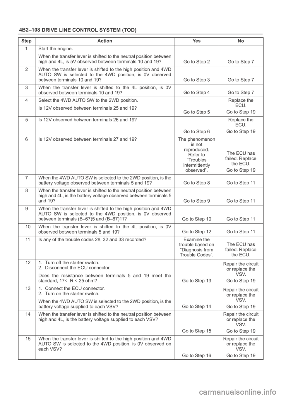
DRIVE LINE CONTROL SYSTEM (TOD) 4B2–108
StepActionYe sNo
1Start the engine.
When the transfer lever is shifted to the neutral position between
high and 4L, is 5V observed between terminals 10 and 19?
Go to Step 2Go to Step 7
2When the transfer lever is shifted to the high position and 4WD
AUTO SW is selected to the 4WD position, is 0V observed
between terminals 10 and 19?
Go to Step 3Go to Step 7
3When the transfer lever is shifted to the 4L position, is 0V
observed between terminals 10 and 19?
Go to Step 4Go to Step 7
4Select the 4WD AUTO SW to the 2WD position.
Is 12V observed between terminals 25 and 19?
Go to Step 5
Replace the
ECU.
Go to Step 19
5Is 12V observed between terminals 26 and 19?
Go to Step 6
Replace the
ECU.
Go to Step 19
6Is 12V observed between terminals 27 and 19?The phenomenon
is not
reproduced.
Refer to
“Troubles
intermittently
observed”.
The ECU has
failed. Replace
the ECU.
Go to Step 19
7When the 4WD AUTO SW is selected to the 2WD position, is the
battery voltage observed between terminals 5 and 19?
Go to Step 8Go to Step 11
8When the transfer lever is shifted to the neutral position between
high and 4L, is the battery voltage observed between terminals 5
and 19?
Go to Step 9Go to Step 11
9When the transfer lever is shifted to the high position and 4WD
AUTO SW is selected to the 4WD position, is 0V observed
between terminals (B–67)5 and (B–67)11?
Go to Step 10Go to Step 11
10When the transfer lever is shifted to the 4L position, is 0V
observed between terminals 5 and 19?
Go to Step 12Go to Step 11
11Is any of the trouble codes 28, 32 and 33 recorded?Examine the
trouble based on
“Diagnosis from
Trouble Codes”.
The ECU has
failed. Replace
the ECU.
121. Turn off the starter switch.
2. Disconnect the ECU connector.
Does the resistance between terminals 5 and 19 meet the
standard, 17< R < 25 ohm?
Go to Step 13
Repair the circuit
or replace the
VSV.
Go to Step 19
131. Connect the ECU connector.
2. Turn on the starter switch.
When the 4WD AUTO SW is selected to the 2WD position, is the
battery voltage supplied to each VSV?
Go to Step 14
Repair the circuit
or replace the
VSV.
Go to Step 19
14When the transfer lever is shifted to the neutral position between
high and 4L, is the battery voltage supplied to each VSV?
Go to Step 15
Repair the circuit
or replace the
VSV.
Go to Step 19
15When the transfer lever is shifted to the high position and 4WD
AUTO SW is selected to the 4WD position, is 0V observed on
each VSV?
Go to Step 16
Repair the circuit
or replace the
VSV.
Go to Step 19
Page 4196 of 6000
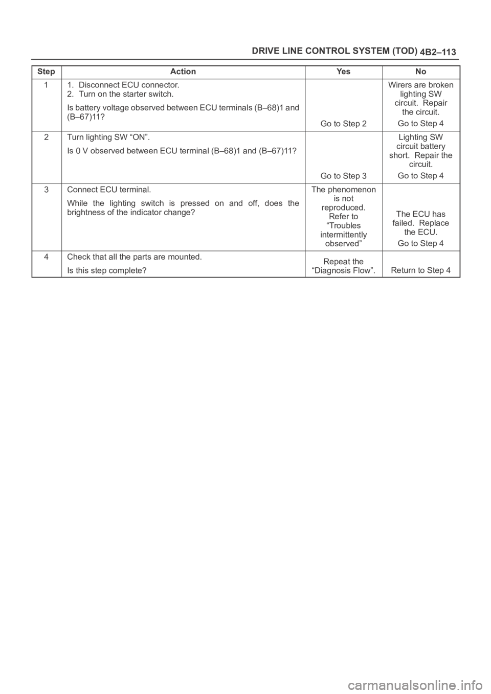
4B2–113 DRIVE LINE CONTROL SYSTEM (TOD)
StepActionYe sNo
11. Disconnect ECU connector.
2. Turn on the starter switch.
Is battery voltage observed between ECU terminals (B–68)1 and
(B–67)11?
Go to Step 2
Wirers are broken
lighting SW
circuit. Repair
the circuit.
Go to Step 4
2Turn lighting SW “ON”.
Is 0 V observed between ECU terminal (B–68)1 and (B–67)11?
Go to Step 3
Lighting SW
circuit battery
short. Repair the
circuit.
Go to Step 4
3Connect ECU terminal.
While the lighting switch is pressed on and off, does the
brightness of the indicator change?The phenomenon
is not
reproduced.
Refer to
“Troubles
intermittently
observed”
The ECU has
failed. Replace
the ECU.
Go to Step 4
4Check that all the parts are mounted.
Is this step complete?Repeat the
“Diagnosis Flow”.
Return to Step 4
Page 4199 of 6000
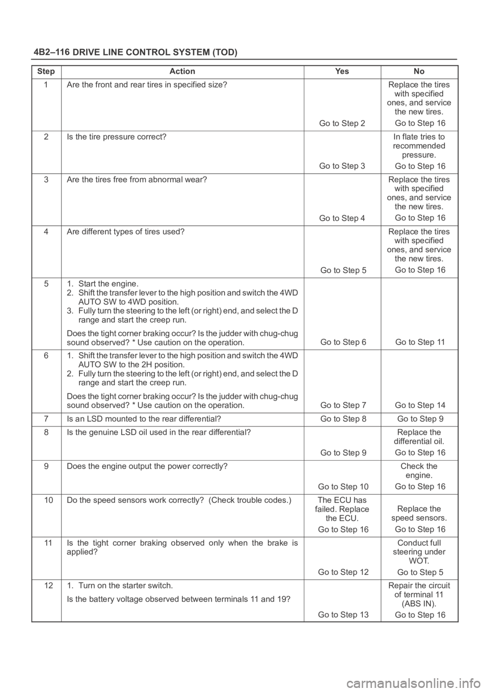
DRIVE LINE CONTROL SYSTEM (TOD) 4B2–116
StepActionYe sNo
1Are the front and rear tires in specified size?
Go to Step 2
Replace the tires
with specified
ones, and service
the new tires.
Go to Step 16
2Is the tire pressure correct?
Go to Step 3
In flate tries to
recommended
pressure.
Go to Step 16
3Are the tires free from abnormal wear?
Go to Step 4
Replace the tires
with specified
ones, and service
the new tires.
Go to Step 16
4Are different types of tires used?
Go to Step 5
Replace the tires
with specified
ones, and service
the new tires.
Go to Step 16
51. Start the engine.
2. Shift the transfer lever to the high position and switch the 4WD
AUTO SW to 4WD position.
3. Fully turn the steering to the left (or right) end, and select the D
range and start the creep run.
Does the tight corner braking occur? Is the judder with chug-chug
sound observed? * Use caution on the operation.
Go to Step 6 Go to Step 11
61. Shift the transfer lever to the high position and switch the 4WD
AUTO SW to the 2H position.
2. Fully turn the steering to the left (or right) end, and select the D
range and start the creep run.
Does the tight corner braking occur? Is the judder with chug-chug
sound observed? * Use caution on the operation.
Go to Step 7 Go to Step 14
7Is an LSD mounted to the rear differential? Go to Step 8 Go to Step 9
8Is the genuine LSD oil used in the rear differential?
Go to Step 9
Replace the
differential oil.
Go to Step 16
9Does the engine output the power correctly?
Go to Step 10
Check the
engine.
Go to Step 16
10Do the speed sensors work correctly? (Check trouble codes.)The ECU has
failed. Replace
the ECU.
Go to Step 16
Replace the
speed sensors.
Go to Step 16
11Is the tight corner braking observed only when the brake is
applied?
Go to Step 12
Conduct full
steering under
WOT.
Go to Step 5
121. Turn on the starter switch.
Is the battery voltage observed between terminals 11 and 19?
Go to Step 13
Repair the circuit
of terminal 11
(ABS IN).
Go to Step 16
Page 4204 of 6000
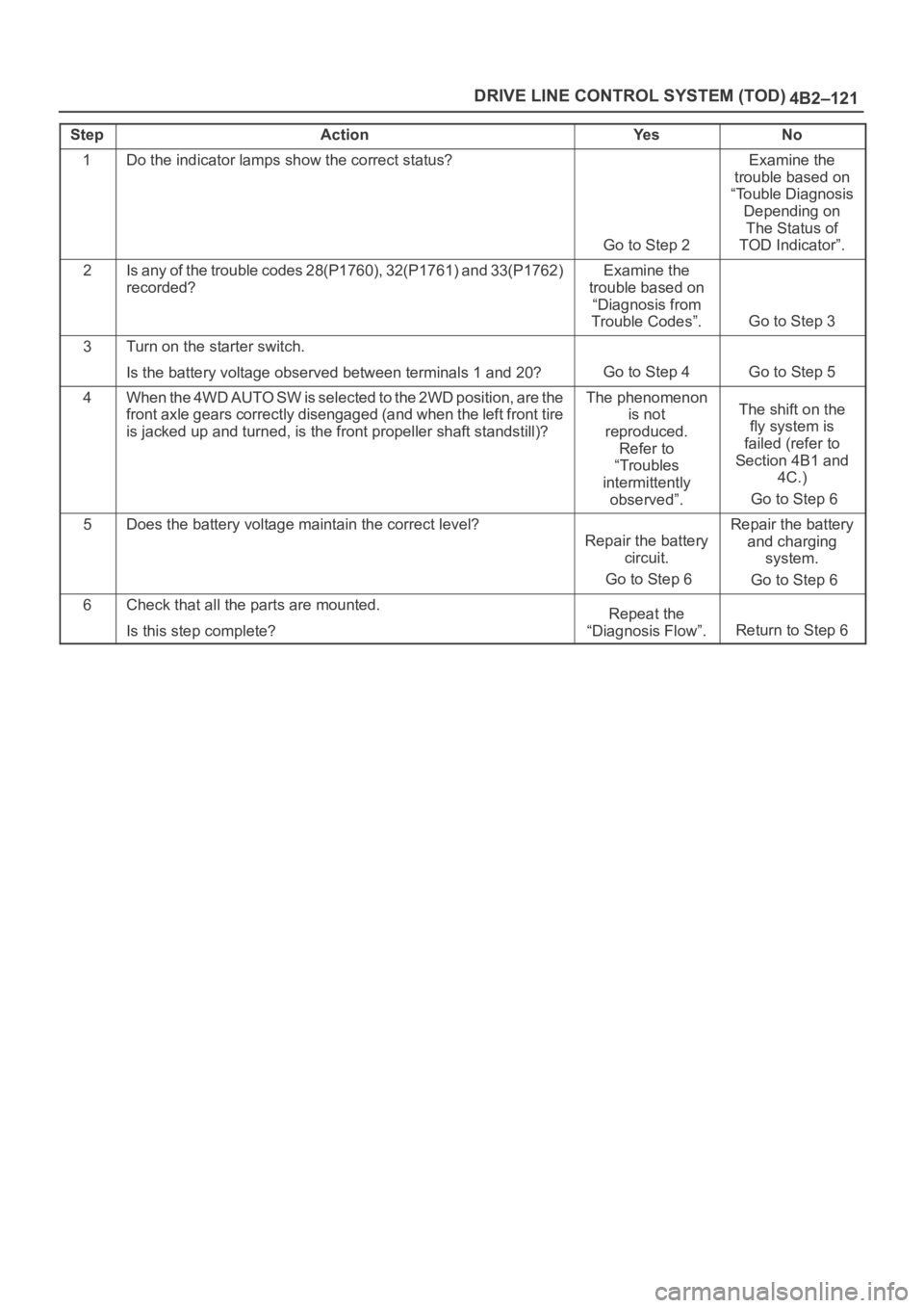
4B2–121 DRIVE LINE CONTROL SYSTEM (TOD)
StepActionYe sNo
1Do the indicator lamps show the correct status?
Go to Step 2
Examine the
trouble based on
“Touble Diagnosis
Depending on
The Status of
TOD Indicator”.
2Is any of the trouble codes 28(P1760), 32(P1761) and 33(P1762)
recorded?Examine the
trouble based on
“Diagnosis from
Trouble Codes”.
Go to Step 3
3Turn on the starter switch.
Is the battery voltage observed between terminals 1 and 20?
Go to Step 4Go to Step 5
4W h e n t h e 4 W D A U T O S W i s s e l e c t e d t o t h e 2 W D p o s i t i o n , a r e t h e
front axle gears correctly disengaged (and when the left front tire
is jacked up and turned, is the front propeller shaft standstill)?The phenomenon
is not
reproduced.
Refer to
“Troubles
intermittently
observed”.The shift on the
fly system is
failed (refer to
Section 4B1 and
4C.)
Go to Step 6
5Does the battery voltage maintain the correct level?
Repair the battery
circuit.
Go to Step 6
Repair the battery
and charging
system.
Go to Step 6
6Check that all the parts are mounted.
Is this step complete?Repeat the
“Diagnosis Flow”.
Return to Step 6
Page 4206 of 6000
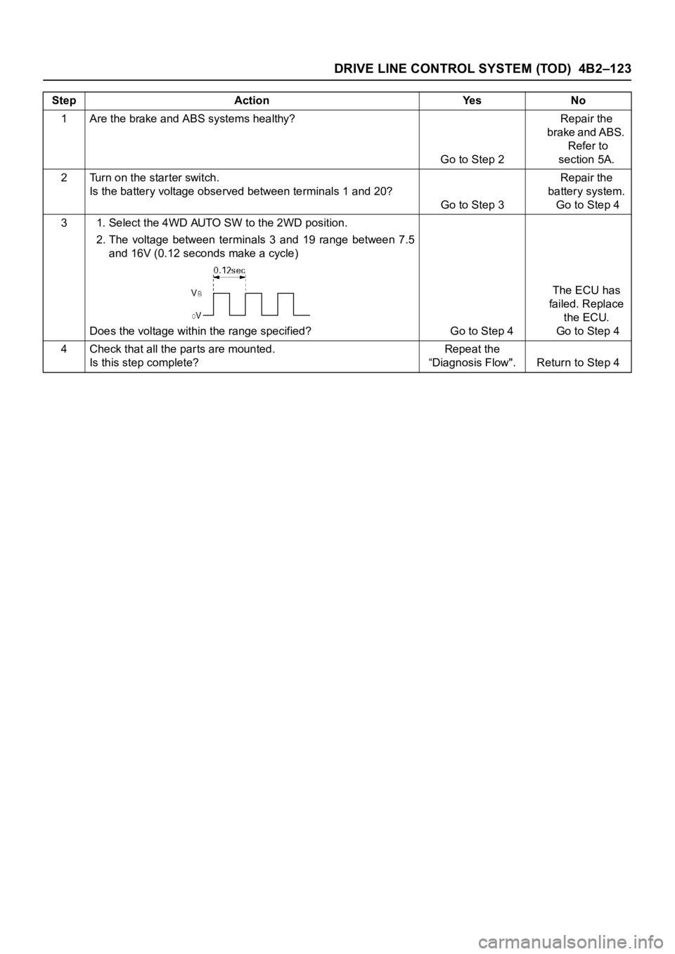
DRIVE LINE CONTROL SYSTEM (TOD) 4B2–123
Step Action Yes No
1 Are the brake and ABS systems healthy?
Go to Step 2Repair the
brake and ABS.
Refer to
section 5A.
2 Turn on the star ter switch.
Is the battery voltage observed between terminals 1 and 20?
Go to Step 3Repair the
battery system.
Go to Step 4
3 1. Select the 4WD AUTO SW to the 2WD position.
2. The voltage between terminals 3 and 19 range between 7.5
and 16V (0.12 seconds make a cycle)
Does the voltage within the range specified? Go to Step 4The ECU has
failed. Replace
the ECU.
Go to Step 4
4 Check that all the par ts are mounted.
Is this step complete?Repeat the
“Diagnosis Flow". Return to Step 4
Page 4270 of 6000
TRANSFER CASE (STANDARD TYPE)
4D1–9
266RW002
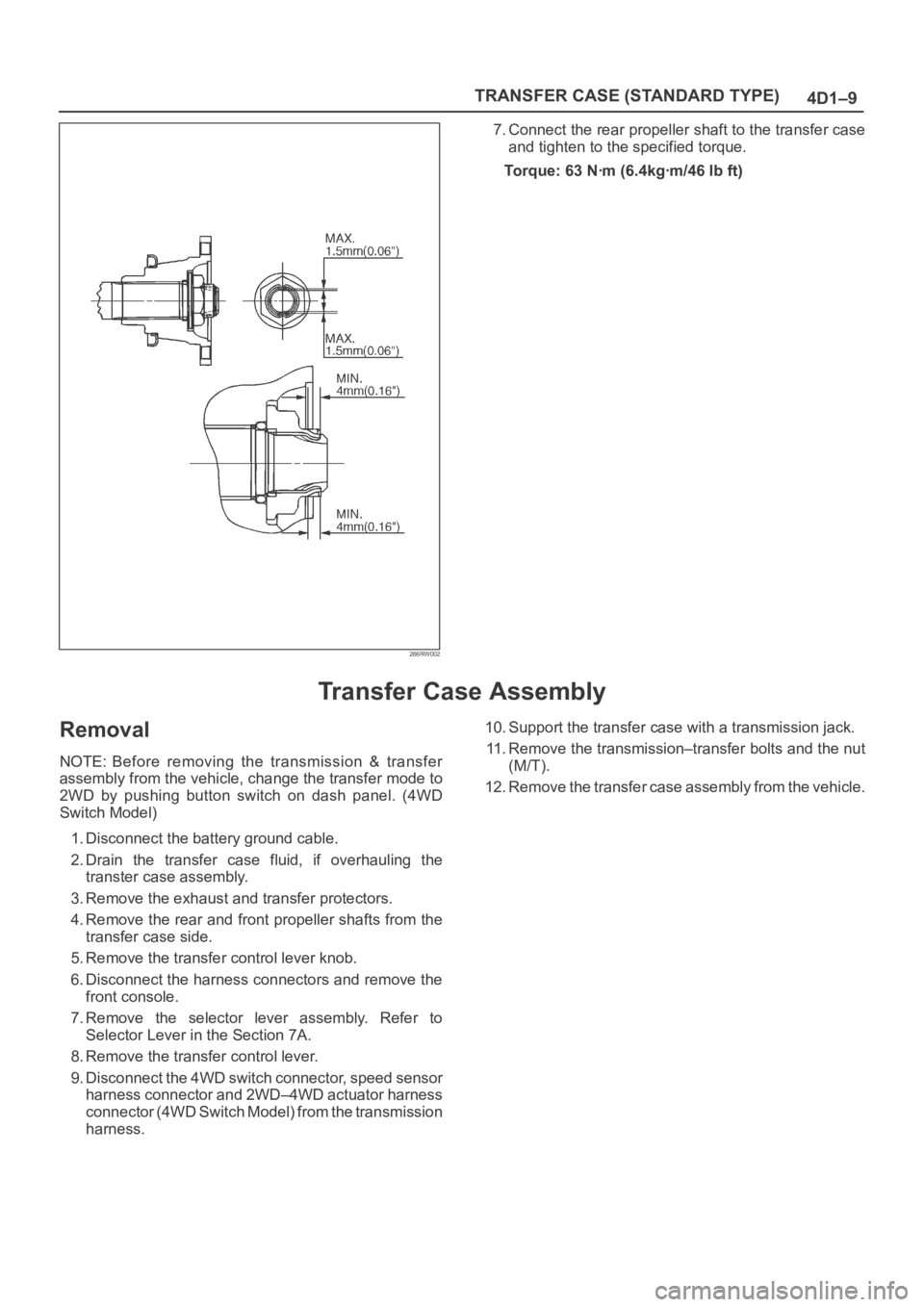
7. Connect the rear propeller shaft to the transfer case
and tighten to the specified torque.
Torque: 63 Nꞏm (6.4kgꞏm/46 lb ft)
Transfer Case Assembly
Removal
NOTE: Before removing the transmission & transfer
assembly from the vehicle, change the transfer mode to
2WD by pushing button switch on dash panel. (4WD
Switch Model)
1. Disconnect the battery ground cable.
2. Drain the transfer case fluid, if overhauling the
transter case assembly.
3. Remove the exhaust and transfer protectors.
4. Remove the rear and front propeller shafts from the
transfer case side.
5. Remove the transfer control lever knob.
6. Disconnect the harness connectors and remove the
front console.
7. Remove the selector lever assembly. Refer to
Selector Lever in the Section 7A.
8. Remove the transfer control lever.
9. Disconnect the 4WD switch connector, speed sensor
harness connector and 2WD–4WD actuator harness
connector (4WD Switch Model) from the transmission
harness.10. Support the transfer case with a transmission jack.
11. Remove the transmission–transfer bolts and the nut
(M/T).
12. Remove the transfer case assembly from the vehicle.