Page 3556 of 6000

10A–5
CRUISE CONTROL SYSTEM
Cruise Control Main Switch
Removal
1. Disconnect the battery ground cable.
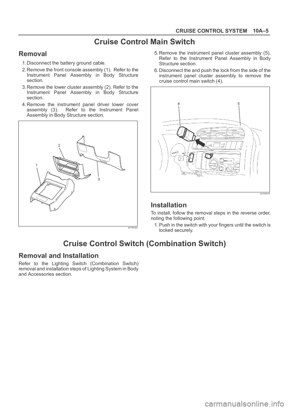
2. Remove the front console assembly (1). Refer to the
Instrument Panel Assembly in Body Structure
section.
3. Remove the lower cluster assembly (2). Refer to the
Instrument Panel Assembly in Body Structure
section.
4. Remove the instrument panel driver lower cover
assembly (3). Refer to the Instrument Panel
Assembly in Body Structure section.
821RW024
5. Remove the instrument panel cluster assembly (5).
Refer to the Instrument Panel Assembly in Body
Structure section.
6. Disconnect the and push the lock from the side of the
instrument panel cluster assembly to remove the
cruise control main switch (4).
821RW079
Installation
To install, follow the removal steps in the reverse order,
noting the following point.
1. Push in the switch with your fingers until the switch is
locked securely.
Cruise Control Switch (Combination Switch)
Removal and Installation
Refer to the Lighting Switch (Combination Switch)
removal and installation steps of Lighting System in Body
and Accessories section.
Page 3557 of 6000
10A–6
CRUISE CONTROL SYSTEM
Cruise Control Unit
Removal
1. Disconnect the battery ground cable.
2. Remove the dash side trim panel (RH)(2).
3. Disconnect the connector.
4. Remove a fixing nut to remove the cruise control unit
(1).
825RW050
Installation
To install, follow the removal steps in the reverse order.
Page 3559 of 6000
10A–8
CRUISE CONTROL SYSTEM
Removal
1. Disconnect the battery ground cable.
2. Remove the cruise actuator Assembly (4).
Disconnect the connector (3).
R e m o v e t h e c a b l e e n d ( 1 ) f r o m t h e c a m l i n k ( c r u i s e
control side).
Loosen two fixing nuts (2).
Remove three actuator fixing screws.
825RW049
Installation
To install, follow the removal steps in the reverse order,
noting the following point.
1. Take care not to bend the cable excessively.
Mode Switch
Removal and Installation
Refer to the Mode Switch removal and installation steps
in Automatic Transmission section.
Page 3754 of 6000
20
25
30A
UT
O
4321
C01RW020
43
3 41
2 21
No continuity between terminals (2) and (4).
Continuity between terminal (2) and (4) when battery
voltage is applied between (1) and (3).
C01RY00003
1
2
3
Terminal
No.Conduction
Conducted (50‰ maximum)
Conducted (100‰ maximum)
Conducted (220‰ maximum) Not conducted
Not conducted 1
�−
23
Te s t i n g
rod
�−
�−
�−
�−
�+
�+
�+
�+
�+
1 23
C01RY00002
Page 4050 of 6000
4B1–5 DRIVE LINE CONTROL SYSTEM (SHIFT ON THE FLY)
4. If vacuum is not applicable as much as –400mmHg,
and if there is resistance on the intake side, replace
with a new check valve.
VSV Assembly
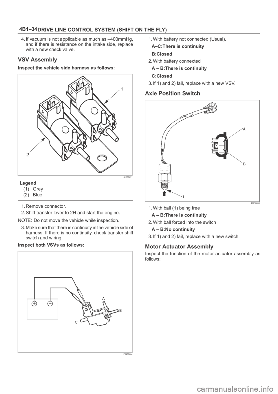
Inspect the vehicle side harness as follows:
412RS071
Legend
(1) Grey
(2) Blue
1. Remove connector.
2. Shift transfer lever to 2H and start the engine.
NOTE: Do not move the vehicle while inspection.
3. Make sure that there is continuity in the vehicle side of
harness. If there is no continuity, check transfer shift
switch and wiring.
Inspect both VSVs as follows:
F04RS004
1. With battery not connected (Usual).
A–C:There is continuity
B:Closed
2. With battery connected
A – B:There is continuity
C:Closed
3. If 1) and 2) fail, replace with a new VSV.
Axle Position Switch
412RS048
1. With ball (1) being free
A – B:There is continuity
2. With ball forced into the switch
A – B:No continuity
3. If 1) and 2) fail, replace with a new switch.
Page 4079 of 6000

4B1–34
DRIVE LINE CONTROL SYSTEM (SHIFT ON THE FLY)
4. If vacuum is not applicable as much as –400mmHg,
and if there is resistance on the intake side, replace
with a new check valve.
VSV Assembly
Inspect the vehicle side harness as follows:
412RS071
Legend
(1) Grey
(2) Blue
1. Remove connector.
2. Shift transfer lever to 2H and start the engine.
NOTE: Do not move the vehicle while inspection.
3. Make sure that there is continuity in the vehicle side of
harness. If there is no continuity, check transfer shift
switch and wiring.
Inspect both VSVs as follows:
F04RS004
1. With battery not connected (Usual).
A–C:There is continuity
B:Closed
2. With battery connected
A – B:There is continuity
C:Closed
3. If 1) and 2) fail, replace with a new VSV.
Axle Position Switch
412RS048
1. With ball (1) being free
A – B:There is continuity
2. With ball forced into the switch
A – B:No continuity
3. If 1) and 2) fail, replace with a new switch.
Motor Actuator Assembly
Inspect the function of the motor actuator assembly as
follows:
Page 4101 of 6000
DRIVE LINE CONTROL SYSTEM (TOD) 4B2–18
Parts Location (RHD 6VE1)
D08RW621
Legend
(1) I–9
(2) B–13 or B–14
(3) H–12
(4) I–12
(5) A–3
(6) H–7, H–8
(7) H–32
(8) C–16
(9) H–5, H–6
(10) C–63
(11) H–49(12) M–22
(13) M–23
(14) M–24
(15) H–10
(16) E–5
(17) E–29
(18) H–42
(19) E–30
(20) Battery
(21) H–13, H–15, H–25, H–26, H–27
(22) Fuse Box
(23) B–67, B–68
Page 4122 of 6000

4B2–39 DRIVE LINE CONTROL SYSTEM (TOD)
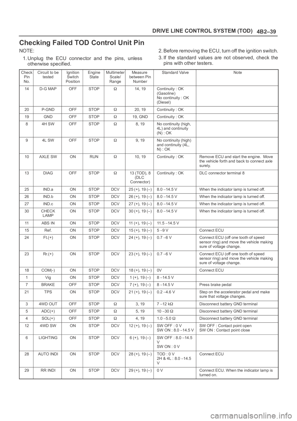
Checking Failed TOD Control Unit Pin
NOTE:
1. Unplug the ECU connector and the pins, unless
otherwise specified.2. Before removing the ECU, turn off the ignition switch.
3. If the standard values are not observed, check the
pins with other testers.
Check
Pin
No.Circuit to be
testedIgnition
Switch
PositionEngine
StateMultimeter
Scale/
RangeMeasure
between Pin
NumberStandard ValveNote
14D-G MAPOFFSTOP14, 19Continuity : OK
(Gasoline)
No continuity : OK
(Diesel)
20P-GNDOFFSTOP20, 19Continuity : OK
19GNDOFFSTOP19, GNDContinuity : OK
84H SWOFFSTOP8, 19No continuity (high,
4L) and continuity
(N) : OK
94L SWOFFSTOP9, 19No continuity (high)
and continuity (4L,
N) : OK
10AXLE SWONRUN10, 19Continuity : OKRemove ECU and start the engine. Move
the vehicle forth and back to connect axle
surely.
13DIAGOFFSTOP13 (TOD), 8
(DLC
Connector)Continuity : OKDLC connector terminal 8
25IND.aONSTOPDCV25 (+), 19 (–)8.0 14.5 VWhen the indicator lamp is turned off.
26IND.bONSTOPDCV26 (+), 19 (–)8.0 14.5 VWhen the indicator lamp is turned off.
27IND.cONSTOPDCV27 (+), 19 (–)8.0 14.5 VWhen the indicator lamp is turned off.
30CHECK
LAMPONSTOPDCV30 (+), 19 (–)8.0 14.5 VWhen the indicator lamp is turned off.
11ABS INONSTOPDCV11 (+), 19 (–)11 . 5 14.5 V
15Ref.ONSTOPDCV15 (+), 19 (–)5 9 VConnect ECU
24Ft.(+)ONSTOPDCV24 (+), 19 (–)0.7 6 VConnect ECU (off one tooth of speed
sensor ring) and move the vehicle making
sure of voltage change.
23Rr.(+)ONSTOPDCV23 (+), 19 (–)0.7 6 VConnect ECU (off one tooth of speed
sensor ring) and move the vehicle making
sure of voltage change.
18COM(-)ONSTOPDCV18 (+), 19 (–)0VConnect ECU
1VigONSTOPDCV1 (+), 19 (–)8 14.5 V
7BRAKEOFFSTOPDCV7 (+), 19 (–)8 14.5 VPress brake pedal
21TPSONSTOPDCV21 (+), 19 (–)0.2 4.6 VStep on the accelerator pedal and make
sure that voltage changes.
34WD OUTOFFSTOP3, 197 12 kDisconnect battery GND terminal
5ADC(+)OFFSTOP5, 1910 30 Disconnect battery GND terminal
4SOL(+)OFFSTOP4, 191.0 5.0 Disconnect battery GND terminal
124WD SWONSTOPDCV12 (+), 19 (–)SW OFF : 0 V
SW ON : 8.0 14.5 VSW OFF : Contact point open
SW ON : Contact point close
6LIGHTINGONSTOPDCV6 (+), 19 (–)SW OFF : 8.0 14.5
V
SW ON : 0 V
28AUTO INDIONSTOPDCV28 (+), 19 (–)TOD : 0 V
2H & 4L : 8.0 14.5
VConnect ECU
29RR INDIONSTOPDCV29 (+), 19 (–)0 VConnect ECU. When the indicator lamp is
turned on.