Page 4275 of 6000
4D1–14
TRANSFER CASE (STANDARD TYPE)
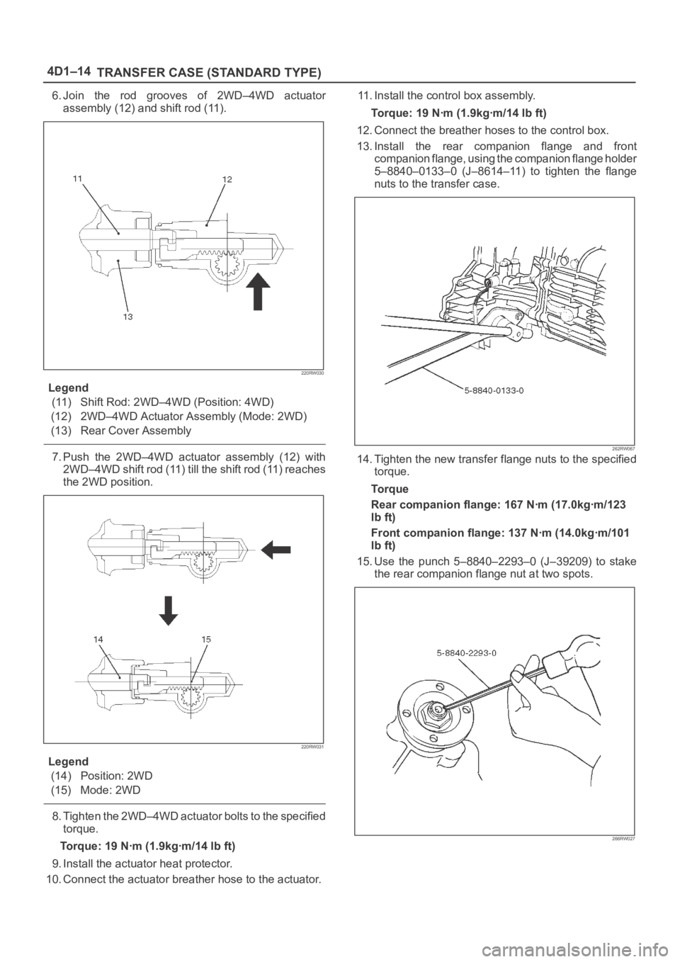
6. Join the rod grooves of 2WD–4WD actuator
assembly (12) and shift rod (11).
220RW030
Legend
(11) Shift Rod: 2WD–4WD (Position: 4WD)
(12) 2WD–4WD Actuator Assembly (Mode: 2WD)
(13) Rear Cover Assembly
7. Push the 2WD–4WD actuator assembly (12) with
2WD–4WD shift rod (11) till the shift rod (11) reaches
the 2WD position.
220RW031
Legend
(14) Position: 2WD
(15) Mode: 2WD
8. Tighten the 2WD–4WD actuator bolts to the specified
torque.
Torque: 19 Nꞏm (1.9kgꞏm/14 lb ft)
9. Install the actuator heat protector.
10. Connect the actuator breather hose to the actuator.11. Install the control box assembly.
Torque: 19 Nꞏm (1.9kgꞏm/14 lb ft)
12. Connect the breather hoses to the control box.
13. Install the rear companion flange and front
companion flange, using the companion flange holder
5–8840–0133–0 (J–8614–11) to tighten the flange
nuts to the transfer case.
262RW067
14. Tighten the new transfer flange nuts to the specified
torque.
To r q u e
Rear companion flange: 167 Nꞏm (17.0kgꞏm/123
lb ft)
Front companion flange: 137 Nꞏm (14.0kgꞏm/101
lb ft)
15. Use the punch 5–8840–2293–0 (J–39209) to stake
the rear companion flange nut at two spots.
266RW027
Page 4276 of 6000
TRANSFER CASE (STANDARD TYPE)
4D1–15
266RW002
16. Stake the front companion flange nut at one spot.
NOTE: Be sure to confirm that there is no crack at the
staked portion of the flange nut after staking.
17. Install the O–ring (8) to the speedometer driven gear
bushing (7).
18. Install the driven gear to the speedometer driven gear
bushing (7).
19. Install the speedometer driven gear assembly to the
transfer rear cover.20. Install the plate (6) to the transfer rear case and
tighten to the specified torque.
Torque: 15 Nꞏm (1.5kgꞏm/11 lb ft)
21. Install the speedometer sensor and tighten to the
specified torque.
Torque: 27 Nꞏm (2.8kgꞏm/20 lb ft)
225RW014
Page 4281 of 6000
4D1–20
TRANSFER CASE (STANDARD TYPE)
Removal
1. Remove the speedometer sensor.
2. Remove the plate.
3. Remove the speedometer driven gear bushing and
driven gear.
NOTE: Apply a reference mark to the driven gear bushing
before removal.
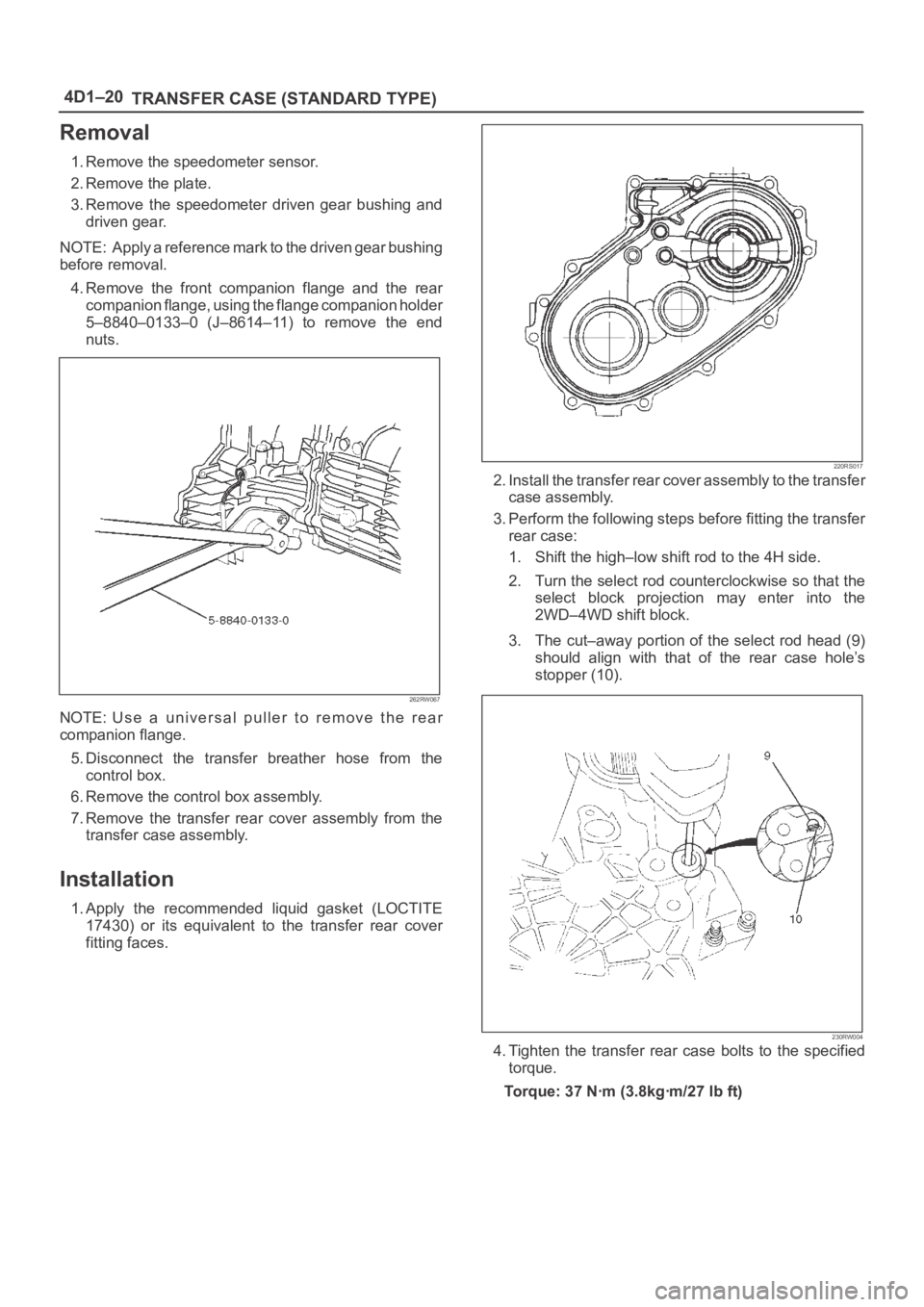
4. Remove the front companion flange and the rear
companion flange, using the flange companion holder
5–8840–0133–0 (J–8614–11) to remove the end
nuts.
262RW067
NOTE: Use a universal puller to remove the rear
companion flange.
5. Disconnect the transfer breather hose from the
control box.
6. Remove the control box assembly.
7. Remove the transfer rear cover assembly from the
transfer case assembly.
Installation
1. Apply the recommended liquid gasket (LOCTITE
17430) or its equivalent to the transfer rear cover
fitting faces.
220RS017
2. Install the transfer rear cover assembly to the transfer
case assembly.
3. Perform the following steps before fitting the transfer
rear case:
1. Shift the high–low shift rod to the 4H side.
2. Turn the select rod counterclockwise so that the
select block projection may enter into the
2WD–4WD shift block.
3. The cut–away portion of the select rod head (9)
should align with that of the rear case hole’s
stopper (10).
230RW004
4. Tighten the transfer rear case bolts to the specified
torque.
Torque: 37 Nꞏm (3.8kgꞏm/27 lb ft)
Page 4282 of 6000
TRANSFER CASE (STANDARD TYPE)
4D1–21
5. Install the control box assembly.
Torque: 19 Nꞏm (1.9kgꞏm/14 lb ft)
6. Connect the breather hoses to the control box.
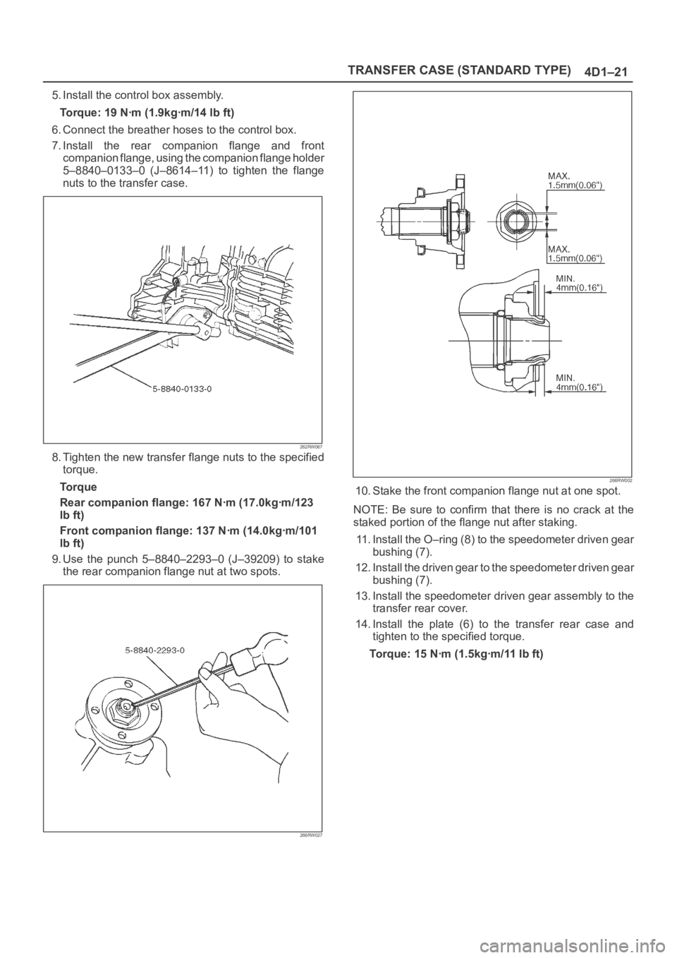
7. Install the rear companion flange and front
companion flange, using the companion flange holder
5–8840–0133–0 (J–8614–11) to tighten the flange
nuts to the transfer case.
262RW067
8. Tighten the new transfer flange nuts to the specified
torque.
Torque
Rear companion flange: 167 Nꞏm (17.0kgꞏm/123
lb ft)
Front companion flange: 137 Nꞏm (14.0kgꞏm/101
lb ft)
9. Use the punch 5–8840–2293–0 (J–39209) to stake
the rear companion flange nut at two spots.
266RW027
266RW002
10. Stake the front companion flange nut at one spot.
NOTE: Be sure to confirm that there is no crack at the
staked portion of the flange nut after staking.
11. Install the O–ring (8) to the speedometer driven gear
bushing (7).
12. Install the driven gear to the speedometer driven gear
bushing (7).
13. Install the speedometer driven gear assembly to the
transfer rear cover.
14. Install the plate (6) to the transfer rear case and
tighten to the specified torque.
Torque: 15 Nꞏm (1.5kgꞏm/11 lb ft)
Page 4283 of 6000
4D1–22
TRANSFER CASE (STANDARD TYPE)
15. Install the speedometer sensor and tighten to the
specified torque.
Torque: 27 Nꞏm (2.8kgꞏm/20 lb ft)
225RW014
Page 4289 of 6000
4D1–28
TRANSFER CASE (STANDARD TYPE)
Inspection and Repair
Refer to “TRANSFER CASE ASSEMBLY” in this section
for inspection and repair.
Reassembly
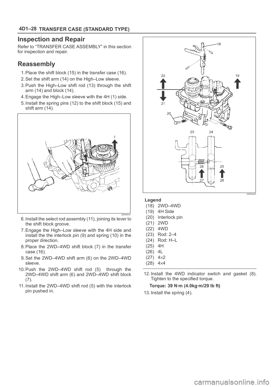
1. Place the shift block (15) in the transfer case (16).
2. Set the shift arm (14) on the High–Low sleeve.
3. Push the High–Low shift rod (13) through the shift
arm (14) and block (14).
4. Engage the High–Low sleeve with the 4H (1) side.
5. Install the spring pins (12) to the shift block (15) and
shift arm (14).
262RW012
6 . I n s t a l l t h e s e l e c t r o d a s s e m b l y ( 11 ) , j o i n i n g i t s l e v e r t o
the shift block groove.
7. Engage the High–Low sleeve with the 4H side and
install the the interlock pin (9) and spring (10) in the
proper direction.
8. Place the 2WD–4WD shift block (7) in the transfer
case (16).
9. Set the 2WD–4WD shift arm (6) on the 2WD–4WD
sleeve.
10. Push the 2WD–4WD shift rod (5) through the
2WD–4WD shift arm (6) and 2WD–4WD shift block
(7).
11. Install the 2WD–4WD shift rod (5) with the interlock
pin pushed in.
262RW035
Legend
(18) 2WD–4WD
(19) 4H Side
(20) Interlock pin
(21) 2WD
(22) 4WD
(23) Rod: 2–4
(24) Rod: H–L
(25) 4H
(26) 4L
(27) 4
2
(28) 4
4
12. Install the 4WD indicator switch and gasket (8).
Tighten to the specified torque.
Torque: 39 Nꞏm (4.0kgꞏm/29 lb ft)
13. Install the spring (4).
Page 4290 of 6000
TRANSFER CASE (STANDARD TYPE)
4D1–29
14. Engage the 2WD–4WD sleeve with the 4WD side and
install the spring pin (3).
262RW022
15. Install the spring pin and bridge (2).
16. Install the detent ball, spring and plug and tighten the
plug (1) to the specified torque.
Torque: 25 Nꞏm (2.5kgꞏm/18 lb ft)
Page 4302 of 6000
TRANSFER CASE (STANDARD TYPE)
4D1–41
27. Use a pair of snap ring pliers to install the snap ring
(19) to the output shaft (5).
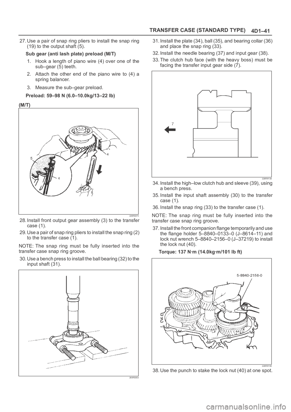
Sub gear (anti lash plate) preload (M/T)
1. Hook a length of piano wire (4) over one of the
sub–gear (5) teeth.
2. Attach the other end of the piano wire to (4) a
spring balancer.
3. Measure the sub–gear preload.
Preload: 59–98 N (6.0–10.0kg/13–22 lb)
(M/T)
226RS075
28. Install front output gear assembly (3) to the transfer
case (1).
29. Use a pair of snap ring pliers to install the snap ring (2)
to the transfer case (1).
NOTE: The snap ring must be fully inserted into the
transfer case snap ring groove.
30. Use a bench press to install the ball bearing (32) to the
input shaft (31).
265RS003
31. Install the plate (34), ball (35), and bearing collar (36)
and place the snap ring (33).
32. Install the needle bearing (37) and input gear (38).
33. The clutch hub face (with the heavy boss) must be
facing the transfer input gear side (7).
226RW136
34. Install the high–low clutch hub and sleeve (39), using
a bench press.
35. Install the input shaft assembly (30) to the transfer
case (1).
36. Install the snap ring (33) to the transfer case (1).
NOTE: The snap ring must be fully inserted into the
transfer case snap ring groove.
37. Install the front companion flange temporarily and use
the flange holder 5–8840–0133–0 (J–8614–11) and
lock nut wrench 5–8840–2156–0 (J–37219) to install
the lock nut (40).
Torque: 137 Nꞏm (14.0kgꞏm/101 lb ft)
226RW190
38. Use the punch to stake the lock nut (40) at one spot.