1998 OPEL FRONTERA torque
[x] Cancel search: torquePage 4032 of 6000
DIFFERENTIAL (REAR 244mm)
4A2B–25
Disassembly
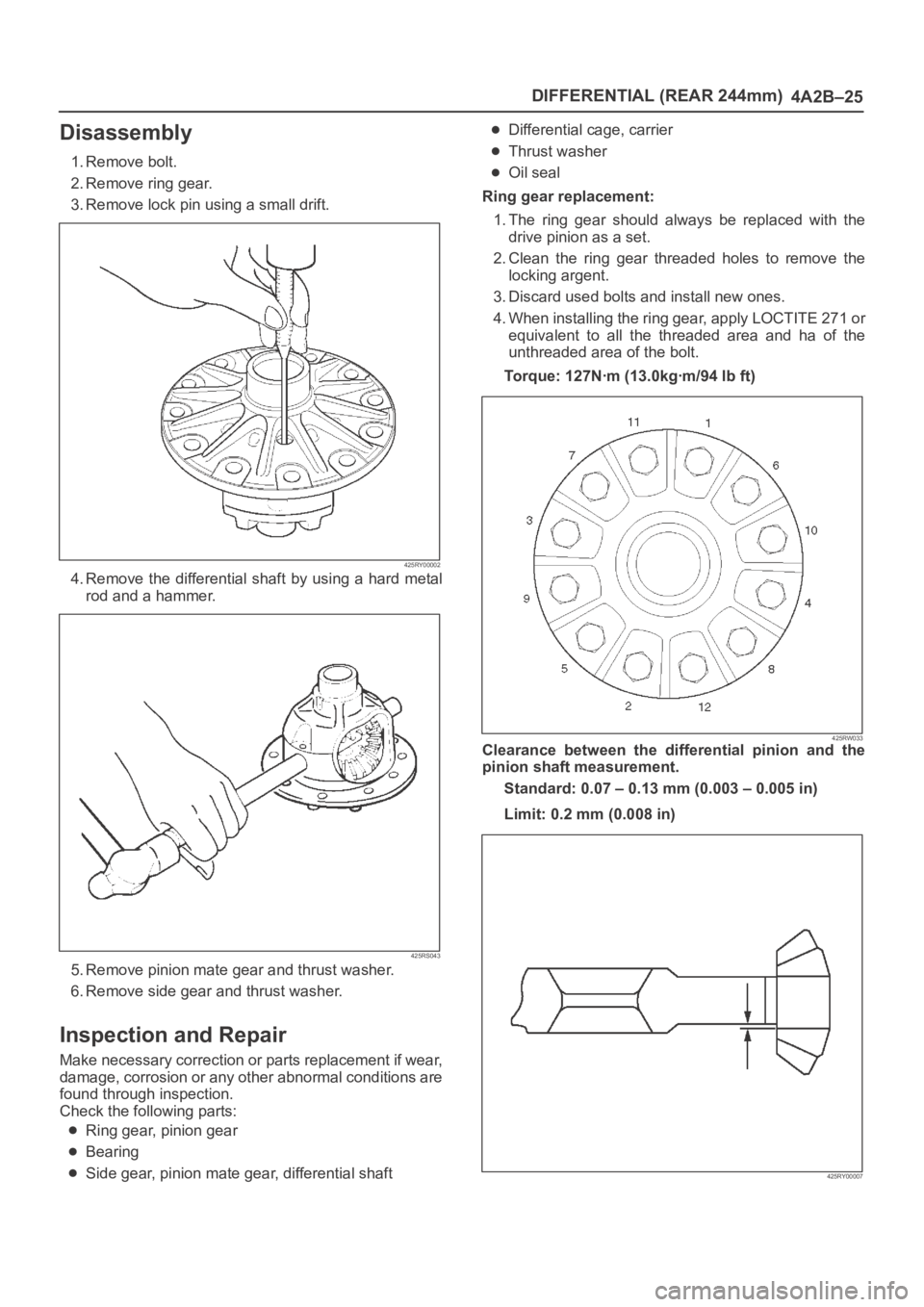
1. Remove bolt.
2. Remove ring gear.
3. Remove lock pin using a small drift.
425RY00002
4. Remove the differential shaft by using a hard metal
rod and a hammer.
425RS043
5. Remove pinion mate gear and thrust washer.
6. Remove side gear and thrust washer.
Inspection and Repair
Make necessary correction or parts replacement if wear,
damage, corrosion or any other abnormal conditions are
found through inspection.
Check the following parts:
Ring gear, pinion gear
Bearing
Side gear, pinion mate gear, differential shaft
Differential cage, carrier
Thrust washer
Oil seal
Ring gear replacement:
1. The ring gear should always be replaced with the
drive pinion as a set.
2. Clean the ring gear threaded holes to remove the
locking argent.
3. Discard used bolts and install new ones.
4. When installing the ring gear, apply LOCTITE 271 or
equivalent to all the threaded area and ha of the
unthreaded area of the bolt.
Torque: 127Nꞏm (13.0kgꞏm/94 lb ft)
425RW033Clearance between the differential pinion and the
pinion shaft measurement.
Standard: 0.07 – 0.13 mm (0.003 – 0.005 in)
Limit: 0.2 mm (0.008 in)
425RY00007
Page 4034 of 6000
DIFFERENTIAL (REAR 244mm)
4A2B–27
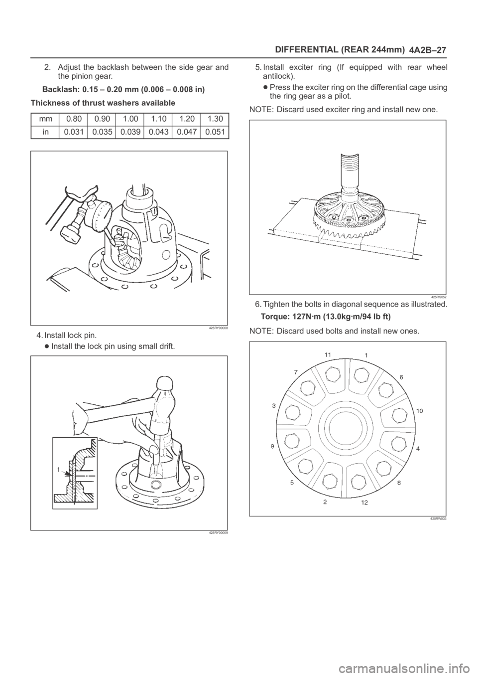
2. Adjust the backlash between the side gear and
the pinion gear.
Backlash: 0.15 – 0.20 mm (0.006 – 0.008 in)
Thickness of thrust washers available
mm
0.800.901.001.101.201.30
in0.0310.0350.0390.0430.0470.051
425RY00008
4. Install lock pin.
Install the lock pin using small drift.
425RY00009
5. Install exciter ring (If equipped with rear wheel
antilock).
Press the exciter ring on the differential cage using
the ring gear as a pilot.
NOTE: Discard used exciter ring and install new one.
425RS052
6. Tighten the bolts in diagonal sequence as illustrated.
Torque: 127Nꞏm (13.0kgꞏm/94 lb ft)
NOTE: Discard used bolts and install new ones.
425RW033
Page 4041 of 6000
4A2B–34DIFFERENTIAL (REAR 244mm)
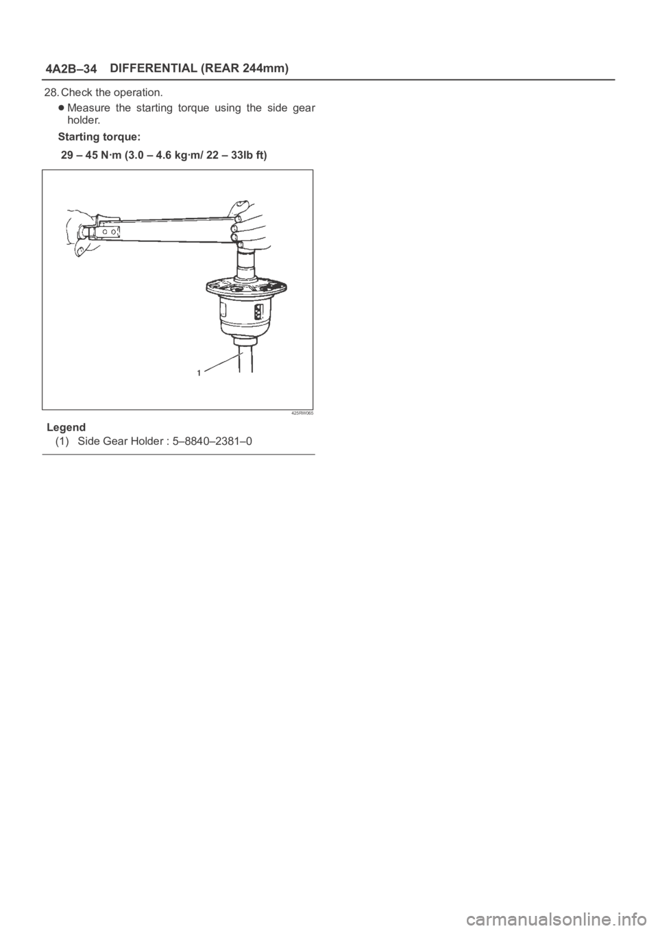
28. Check the operation.
Measure the starting torque using the side gear
holder.
Starting torque:
29–45Nꞏm(3.0–4.6kgꞏm/22–33Ibft)
425RW065
Legend
(1) Side Gear Holder : 5–8840–2381–0
Page 4043 of 6000
4A2B–36DIFFERENTIAL (REAR 244mm)
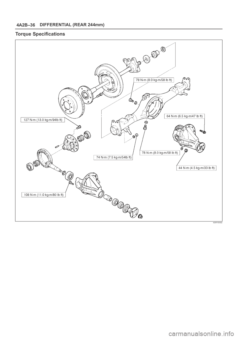
Torque Specifications
420RY00002
Page 4046 of 6000
4B1–1 DRIVE LINE CONTROL SYSTEM (SHIFT ON THE FLY)
DRIVELINE/AXLE
DRIVELINE CONTROL SYSTEM (SHIFT ON THE FLY)
CONTENTS
Service Precaution 4B1–1. . . . . . . . . . . . . . . . . . . . . .
Shift on the Fly System (Lever Type) 4B1–2. . . . . . .
Outline of Shift on the Fly System
(Lever Type) 4B1–2. . . . . . . . . . . . . . . . . . . . . . . . . . .
Shift on the Fly Vacuum Piping and Electric
Equipment (For Lever Control Type) 4B1–3. . . . . .
Vacuum Piping Diagram 4B1–3. . . . . . . . . . . . . . . .
Inspection and Repair 4B1–4. . . . . . . . . . . . . . . . . .
Shift on the Fly System (Push Button Type) 4B1–7.
Outline of Shift on the Fly System
(Push Button Type) 4B1–7. . . . . . . . . . . . . . . . . . . . Functions of Indicator Lamp 4B1–11. . . . . . . . . . . . . . .
Diagnosis 4B1–11. . . . . . . . . . . . . . . . . . . . . . . . . . . . .
Front Axle Diagnosis 4B1–30. . . . . . . . . . . . . . . . . . .
Shift on the Fly Vacuum Piping and Electric
Equipment (For Push Button Type) 4B1–32. . . . . . . .
Vacuum Piping Diagram 4B1–32. . . . . . . . . . . . . . . .
Inspection and Repair 4B1–33. . . . . . . . . . . . . . . . . .
4WD Control Unit (For Push Button Type) 4B1–36. .
4WD Control Unit Associated Parts 4B1–36. . . . . .
Removal 4B1–37. . . . . . . . . . . . . . . . . . . . . . . . . . . . .
Installation 4B1–37. . . . . . . . . . . . . . . . . . . . . . . . . . . .
Service Precaution
WARNING: IF SO EQUIPPED WITH A
SUPPLEMENTAL RESTRAINT SYSTEM (SRS),
REFER TO THE SRS COMPONENT AND WIRING
LOCATION VIEW IN ORDER TO DETERMINE
WHETHER YOU ARE PERFORMING SERVICE ON OR
NEAR THE SRS COMPONENTS OR THE SRS
WIRING. WHEN YOU ARE PERFORMING SERVICE
ON OR NEAR THE SRS COMPONENTS OR THE SRS
WIRING, REFER TO THE SRS SERVICE
INFORMATION. FAILURE TO FOLLOW WARNINGS
COULD RESULT IN POSSIBLE AIR BAG
DEPLOYMENT, PERSONAL INJURY, OR
OTHERWISE UNNEEDED SRS SYSTEM REPAIRS.
CAUTION: Always use the correct fastener in the
proper location. When you replace a fastener, use
ONLY the exact part number for that application.
ISUZU will call out those fasteners that require a
replacement after removal. ISUZU will also call out
the fasteners that require thread lockers or thread
sealant. UNLESS OTHERWISE SPECIFIED, do not
use supplemental coatings (Paints, greases, or other
corrosion inhibitors) on threaded fasteners or
fastener joint interfaces. Generally, such coatings
adversely affect the fastener torque and the joint
clamping force, and may damage the fastener. When
you install fasteners, use the correct tightening
sequence and specifications. Following these
instructions can help you avoid damage to parts and
systems.
Page 4056 of 6000
4B1–11 DRIVE LINE CONTROL SYSTEM (SHIFT ON THE FLY)
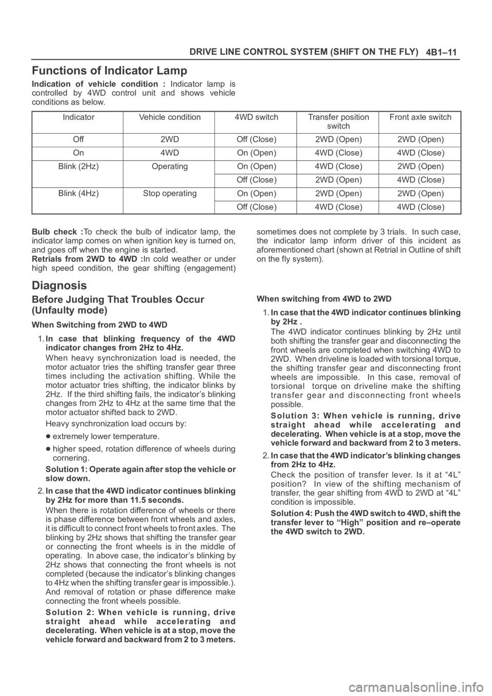
Functions of Indicator Lamp
Indication of vehicle condition : Indicator lamp is
controlled by 4WD control unit and shows vehicle
conditions as below.
Indicator
Vehicle condition4WD switchTransfer position
switchFront axle switch
Off2WDOff (Close)2WD (Open)2WD (Open)
On4WDOn (Open)4WD (Close)4WD (Close)
Blink (2Hz)OperatingOn (Open)4WD (Close)2WD (Open)
Off (Close)2WD (Open)4WD (Close)
Blink (4Hz)Stop operatingOn (Open)2WD (Open)2WD (Open)
Off (Close)4WD (Close)4WD (Close)
Bulb check :To check the bulb of indicator lamp, the
indicator lamp comes on when ignition key is turned on,
and goes off when the engine is started.
Retrials from 2WD to 4WD :In cold weather or under
high speed condition, the gear shifting (engagement)sometimes does not complete by 3 trials. In such case,
the indicator lamp inform driver of this incident as
aforementioned chart (shown at Retrial in Outline of shift
on the fly system).
Diagnosis
Before Judging That Troubles Occur
(Unfaulty mode)
When Switching from 2WD to 4WD
1.In case that blinking frequency of the 4WD
indicator changes from 2Hz to 4Hz.
When heavy synchronization load is needed, the
motor actuator tries the shifting transfer gear three
times including the activation shifting. While the
motor actuator tries shifting, the indicator blinks by
2Hz. If the third shifting fails, the indicator’s blinking
changes from 2Hz to 4Hz at the same time that the
motor actuator shifted back to 2WD.
Heavy synchronization load occurs by:
extremely lower temperature.
higher speed, rotation difference of wheels during
cornering.
Solution 1: Operate again after stop the vehicle or
slow down.
2.In case that the 4WD indicator continues blinking
by 2Hz for more than 11.5 seconds.
When there is rotation difference of wheels or there
is phase difference between front wheels and axles,
it is difficult to connect front wheels to front axles. The
blinking by 2Hz shows that shifting the transfer gear
or connecting the front wheels is in the middle of
operating. In above case, the indicator’s blinking by
2Hz shows that connecting the front wheels is not
completed (because the indicator’s blinking changes
to 4Hz when the shifting transfer gear is impossible.).
And removal of rotation or phase difference make
connecting the front wheels possible.
Solution 2: When vehicle is running, drive
straight ahead while accelerating and
decelerating. When vehicle is at a stop, move the
vehicle forward and backward from 2 to 3 meters.When switching from 4WD to 2WD
1.In case that the 4WD indicator continues blinking
by 2Hz .
The 4WD indicator continues blinking by 2Hz until
both shifting the transfer gear and disconnecting the
front wheels are completed when switching 4WD to
2WD. When driveline is loaded with torsional torque,
the shifting transfer gear and disconnecting front
wheels are impossible. In this case, removal of
torsional torque on driveline make the shifting
transfer gear and disconnecting front wheels
possible.
Solution 3: When vehicle is running, drive
straight ahead while accelerating and
decelerating. When vehicle is at a stop, move the
vehicle forward and backward from 2 to 3 meters.
2.In case that the 4WD indicator’s blinking changes
from 2Hz to 4Hz.
Check the position of transfer lever. Is it at “4L”
position? In view of the shifting mechanism of
transfer, the gear shifting from 4WD to 2WD at “4L”
condition is impossible.
Solution 4: Push the 4WD switch to 4WD, shift the
transfer lever to “High” position and re–operate
the 4WD switch to 2WD.
Page 4084 of 6000
4B2–1 DRIVE LINE CONTROL SYSTEM (TOD)
DRIVELINE/AXLE
DRIVELINE CONTROL SYSTEM (TOD)
CONTENTS
Service Precaution 4B2–1. . . . . . . . . . . . . . . . . . . . . .
General Description 4B2–2. . . . . . . . . . . . . . . . . . . . .
System Components 4B2–4. . . . . . . . . . . . . . . . . . . .
Parts Location 4B2–4. . . . . . . . . . . . . . . . . . . . . . . .
Functions of Indicator Lamp 4B2–8. . . . . . . . . . . . . .
Diagnosis 4B2–13. . . . . . . . . . . . . . . . . . . . . . . . . . . . . .
Basic Diagnostic Flow Chart 4B2–17. . . . . . . . . . . . . .
Parts Location 4B2–18. . . . . . . . . . . . . . . . . . . . . . . . . .
Circuit Diagram 4B2–22. . . . . . . . . . . . . . . . . . . . . . . . . Connector List 4B2–34. . . . . . . . . . . . . . . . . . . . . . . . . .
Checking Failed Pin 4B2–36. . . . . . . . . . . . . . . . . . . . .
Checking Failed TOD Control Unit Pin 4B2–39. . . . .
Diagnostic Trouble Codes 4B2–43. . . . . . . . . . . . . . . .
Diagnosis from Trouble Codes 4B2–44. . . . . . . . . . . .
Trouble Diagnosis Depending on The Status
of TOD Indicator 4B2–74. . . . . . . . . . . . . . . . . . . . . . . .
Diagnosis from Symptom 4B2–114. . . . . . . . . . . . . . . . .
Service Precaution
WARNING: IF SO EQUIPPED WITH A
SUPPLEMENTAL RESTRAINT SYSTEM (SRS),
REFER TO THE SRS COMPONENT AND WIRING
LOCATION VIEW IN ORDER TO DETERMINE
WHETHER YOU ARE PERFORMING SERVICE ON OR
NEAR THE SRS COMPONENTS OR THE SRS
WIRING. WHEN YOU ARE PERFORMING SERVICE
ON OR NEAR THE SRS COMPONENTS OR THE SRS
WIRING, REFER TO THE SRS SERVICE
INFORMATION. FAILURE TO FOLLOW WARNINGS
COULD RESULT IN POSSIBLE AIR BAG
DEPLOYMENT, PERSONAL INJURY, OR
OTHERWISE UNNEEDED SRS SYSTEM REPAIRS.CAUTION: Always use the correct fastener in the
proper location. When you replace a fastener, use
ONLY the exact part number for that application.
ISUZU will call out those fasteners that require a
replacement after removal. ISUZU will also call out
the fasteners that require thread lockers or thread
sealant. UNLESS OTHERWISE SPECIFIED, do not
use supplemental coatings (Paints, greases, or other
corrosion inhibitors) on threaded fasteners or
fastener joint interfaces. Generally, such coatings
adversely affect the fastener torque and the joint
clamping force, and may damage the fastener. When
you install fasteners, use the correct tightening
sequence and specifications. Following these
instructions can help you avoid damage to parts and
systems.
Page 4085 of 6000
DRIVE LINE CONTROL SYSTEM (TOD) 4B2–2
General Description
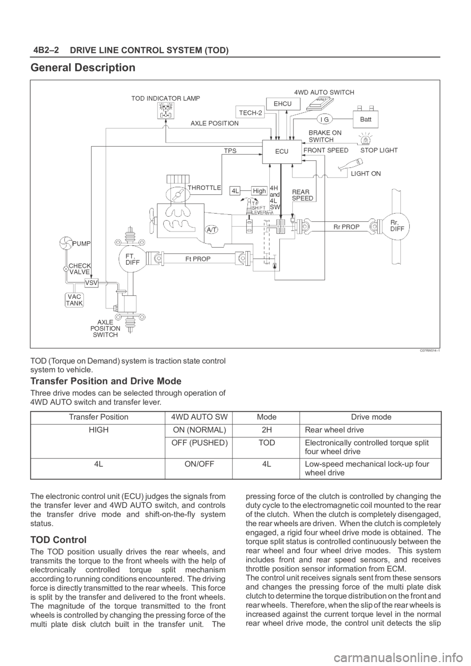
C07RW014–1
TOD (Torque on Demand) system is traction state control
system to vehicle.
Transfer Position and Drive Mode
Three drive modes can be selected through operation of
4WD AUTO switch and transfer lever.
Transfer Position
4WD AUTO SWModeDrive mode
HIGHON (NORMAL)2HRear wheel drive
OFF (PUSHED)TODElectronically controlled torque split
four wheel drive
4LON/OFF4LLow-speed mechanical lock-up four
wheel drive
The electronic control unit (ECU) judges the signals from
the transfer lever and 4WD AUTO switch, and controls
the transfer drive mode and shift-on-the-fly system
status.
TOD Control
The TOD position usually drives the rear wheels, and
transmits the torque to the front wheels with the help of
electronically controlled torque split mechanism
according to running conditions encountered. The driving
force is directly transmitted to the rear wheels. This force
is split by the transfer and delivered to the front wheels.
The magnitude of the torque transmitted to the front
wheels is controlled by changing the pressing force of the
multi plate disk clutch built in the transfer unit. Thepressing force of the clutch is controlled by changing the
duty cycle to the electromagnetic coil mounted to the rear
of the clutch. When the clutch is completely disengaged,
the rear wheels are driven. When the clutch is completely
engaged, a rigid four wheel drive mode is obtained. The
torque split status is controlled continuously between the
rear wheel and four wheel drive modes. This system
includes front and rear speed sensors, and receives
throttle position sensor information from ECM.
The control unit receives signals sent from these sensors
and changes the pressing force of the multi plate disk
clutch to determine the torque distribution on the front and
rear wheels. Therefore, when the slip of the rear wheels is
increased against the current torque level in the normal
rear wheel drive mode, the control unit detects the slip