1998 OPEL FRONTERA warning
[x] Cancel search: warningPage 1092 of 6000
6D3–1 STARTING AND CHARGING SYSTEM
ENGINE
STARTING AND CHARGING SYSTEM
CONTENTS
Service Precaution 6D3–1. . . . . . . . . . . . . . . . . . . . . .
Starting System 6D3–2. . . . . . . . . . . . . . . . . . . . . . . . .
General Description 6D3–2. . . . . . . . . . . . . . . . . . . . .
Diagnosis 6D3–4. . . . . . . . . . . . . . . . . . . . . . . . . . . . . .
Starter 6D3–5. . . . . . . . . . . . . . . . . . . . . . . . . . . . . . . . .
Removal 6D3–5. . . . . . . . . . . . . . . . . . . . . . . . . . . . .
Installation 6D3–5. . . . . . . . . . . . . . . . . . . . . . . . . . . .
Disassembled View 6D3–6. . . . . . . . . . . . . . . . . . . .
Disassembly 6D3–7. . . . . . . . . . . . . . . . . . . . . . . . . .
Inspection and Repair 6D3–9. . . . . . . . . . . . . . . . . .
Reassembly 6D3–13. . . . . . . . . . . . . . . . . . . . . . . . . .
Main Data and Specifications 6D3–15. . . . . . . . . . .
Charging System 6D3–18. . . . . . . . . . . . . . . . . . . . . . . . General Description 6D3–18. . . . . . . . . . . . . . . . . . . . .
General On–Vehicle Inspection 6D3–18. . . . . . . . . . .
Generator 6D3–19. . . . . . . . . . . . . . . . . . . . . . . . . . . . . .
Removal 6D3–19. . . . . . . . . . . . . . . . . . . . . . . . . . . . .
Inspection 6D3–19. . . . . . . . . . . . . . . . . . . . . . . . . . . .
Installation 6D3–19. . . . . . . . . . . . . . . . . . . . . . . . . . . .
Disassembled View 6D3–20. . . . . . . . . . . . . . . . . . . .
Disassembly 6D3–21. . . . . . . . . . . . . . . . . . . . . . . . . .
Inspection and Repair 6D3–23. . . . . . . . . . . . . . . . . .
Reassembly 6D3–24. . . . . . . . . . . . . . . . . . . . . . . . . .
Bench Test 6D3–25. . . . . . . . . . . . . . . . . . . . . . . . . . .
Main Data and Specifications 6D3–26. . . . . . . . . . .
Service Precaution
WARNING: IF SO EQUIPPED WITH A
SUPPLEMENTAL RESTRAINT SYSTEM (SRS),
REFER TO THE SRS COMPONENT AND WIRING
LOCATION VIEW IN ORDER TO DETERMINE
WHETHER YOU ARE PERFORMING SERVICE ON OR
NEAR THE SRS COMPONENTS OR THE SRS
WIRING. WHEN YOU ARE PERFORMING SERVICE
ON OR NEAR THE SRS COMPONENTS OR THE SRS
WIRING, REFER TO THE SRS SERVICE
INFORMATION. FAILURE TO FOLLOW WARNINGS
COULD RESULT IN POSSIBLE AIR BAG
DEPLOYMENT, PERSONAL INJURY, OR
OTHERWISE UNNEEDED SRS SYSTEM REPAIRS.
CAUTION: Always use the correct fastener in the
proper location. When you replace a fastener, use
ONLY the exact part number for that application.
ISUZU will call out those fasteners that require a
replacement after removal. ISUZU will also call out
the fasteners that require thread lockers or thread
sealant. UNLESS OTHERWISE SPECIFIED, do not
use supplemental coatings (Paints, greases, or other
corrosion inhibitors) on threaded fasteners or
fastener joint interfaces. Generally, such coatings
adversely affect the fastener torque and the joint
clamping force, and may damage the fastener. When
you install fasteners, use the correct tightening
sequence and specifications. Following these
instructions can help you avoid damage to parts and
systems.
Page 1109 of 6000
6D3–18STARTING AND CHARGING SYSTEM
Charging System
General Description
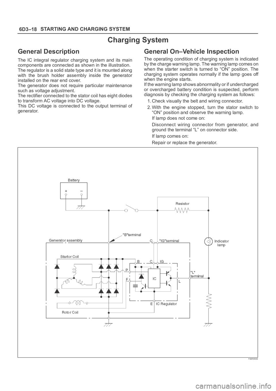
The IC integral regulator charging system and its main
components are connected as shown in the illustration.
The regulator is a solid state type and it is mounted along
with the brush holder assembly inside the generator
installed on the rear end cover.
The generator does not require particular maintenance
such as voltage adjustment.
The rectifier connected to the stator coil has eight diodes
to transform AC voltage into DC voltage.
This DC voltage is connected to the output terminal of
generator.
General On–Vehicle Inspection
The operating condition of charging system is indicated
by the charge warning lamp. The warning lamp comes on
when the starter switch is turned to “ON” position. The
charging system operates normally if the lamp goes off
when the engine starts.
If the warning lamp shows abnormality or if undercharged
or overcharged battery condition is suspected, perform
diagnosis by checking the charging system as follows:
1. Check visually the belt and wiring connector.
2. With the engine stopped, turn the stator switch to
“ON” position and observe the warning lamp.
If lamp does not come on:
Disconnect wiring connector from generator, and
ground the terminal “L” on connector side.
If lamp comes on:
Repair or replace the generator.
F06RW009
Page 1116 of 6000
6D3–25 STARTING AND CHARGING SYSTEM
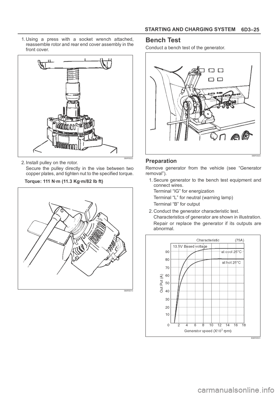
1. Using a press with a socket wrench attached,
reassemble rotor and rear end cover assembly in the
front cover.
066RS022
2. Install pulley on the rotor.
Secure the pulley directly in the vise between two
copper plates, and tighten nut to the specified torque.
Torque: 111 Nꞏm (11.3 Kgꞏm/82 lb ft)
066RS010
Bench Test
Conduct a bench test of the generator.
066RS023
Preparation
Remove generator from the vehicle (see “Generator
removal”).
1. Secure generator to the bench test equipment and
connect wires.
Terminal “IG” for energization
Terminal “L” for neutral (warning lamp)
Terminal “B” for output
2. Conduct the generator characteristic test.
Characteristics of generator are shown in illustration.
Repair or replace the generator if its outputs are
abnormal.
B06RW001
Page 1415 of 6000
6E–298
ENGINE DRIVEABILITY AND EMISSIONS
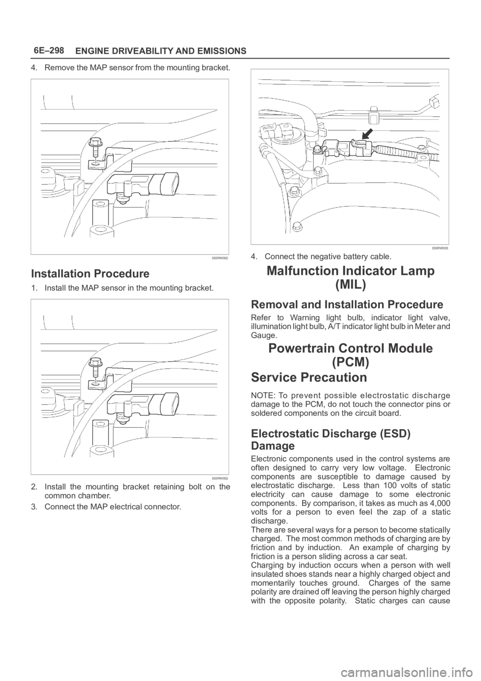
4. Remove the MAP sensor from the mounting bracket.
055RW002
Installation Procedure
1. Install the MAP sensor in the mounting bracket.
055RW002
2. Install the mounting bracket retaining bolt on the
common chamber.
3. Connect the MAP electrical connector.
055RW005
4. Connect the negative battery cable.
Malfunction Indicator Lamp
(MIL)
Removal and Installation Procedure
Refer to Warning light bulb, indicator light valve,
illumination light bulb, A/T indicator light bulb in Meter and
Gauge.
Powertrain Control Module
(PCM)
Service Precaution
NOTE: To prevent possible electrostatic discharge
damage to the PCM, do not touch the connector pins or
soldered components on the circuit board.
Electrostatic Discharge (ESD)
Damage
Electronic components used in the control systems are
often designed to carry very low voltage. Electronic
components are susceptible to damage caused by
electrostatic discharge. Less than 100 volts of static
electricity can cause damage to some electronic
components. By comparison, it takes as much as 4,000
volts for a person to even feel the zap of a static
discharge.
There are several ways for a person to become statically
charged. The most common methods of charging are by
friction and by induction. An example of charging by
friction is a person sliding across a car seat.
Charging by induction occurs when a person with well
insulated shoes stands near a highly charged object and
momentarily touches ground. Charges of the same
polarity are drained off leaving the person highly charged
with the opposite polarity. Static charges can cause
Page 1472 of 6000
6F–1 ENGINE EXHAUST
ENGINE
ENGINE EXHAUST
CONTENTS
Service Precaution 6F–1. . . . . . . . . . . . . . . . . . . . . .
General Description 6F–2. . . . . . . . . . . . . . . . . . . . .
Front Exhaust Pipe 6F–4. . . . . . . . . . . . . . . . . . . . . .
Front Exhaust Pipe and Associated Parts 6F–4.
Removal 6F–4. . . . . . . . . . . . . . . . . . . . . . . . . . . . .
Installation 6F–4. . . . . . . . . . . . . . . . . . . . . . . . . . . .
Three Way Catalytic Converter 6F–5. . . . . . . . . . . .
Removal 6F–5. . . . . . . . . . . . . . . . . . . . . . . . . . . . .
Installation 6F–5. . . . . . . . . . . . . . . . . . . . . . . . . . . . Exhaust Silencer 6F–6. . . . . . . . . . . . . . . . . . . . . . . .
Exhaust Silencer and Associated Parts 6F–6. . .
Removal 6F–6. . . . . . . . . . . . . . . . . . . . . . . . . . . . .
Installation 6F–6. . . . . . . . . . . . . . . . . . . . . . . . . . . .
Rear Exhaust pipe 6F–7. . . . . . . . . . . . . . . . . . . . . . .
Rear Exhaust pipe and Associated Parts 6F–7.
Removal 6F–7. . . . . . . . . . . . . . . . . . . . . . . . . . . . .
Installation 6F–7. . . . . . . . . . . . . . . . . . . . . . . . . . . .
Main Data and Specifications 6F–8. . . . . . . . . . . . .
Service Precaution
WARNING: IF SO EQUIPPED WITH A
SUPPLEMENTAL RESTRAINT SYSTEM (SRS),
REFER TO THE SRS COMPONENT AND WIRING
LOCATION VIEW IN ORDER TO DETERMINE
WHETHER YOU ARE PERFORMING SERVICE ON OR
NEAR THE SRS COMPONENTS OR THE SRS
WIRING. WHEN YOU ARE PERFORMING SERVICE
ON OR NEAR THE SRS COMPONENTS OR THE SRS
WIRING, REFER TO THE SRS SERVICE
INFORMATION. FAILURE TO FOLLOW WARNINGS
COULD RESULT IN POSSIBLE AIR BAG
DEPLOYMENT, PERSONAL INJURY, OR
OTHERWISE UNNEEDED SRS SYSTEM REPAIRS.
CAUTION: Always use the correct fastener in the
proper location. When you replace a fastener, use
ONLY the exact part number for that application.
ISUZU will call out those fasteners that require a
replacement after removal. ISUZU will also call out
the fasteners that require thread lockers or thread
sealant. UNLESS OTHERWISE SPECIFIED, do not
use supplemental coatings (Paints, greases, or other
corrosion inhibitors) on threaded fasteners or
fastener joint interfaces. Generally, such coatings
adversely affect the fastener torque and the joint
clamping force, and may damage the fastener. When
you install fasteners, use the correct tightening
sequence and specifications. Following these
instructions can help you avoid damage to parts and
systems.
Page 1480 of 6000
6G–1 ENGINE LUBRICATION
ENGINE
ENGINE LUBRICATION
CONTENTS
Service Precaution 6G–1. . . . . . . . . . . . . . . . . . . . . .
General Description 6G–2. . . . . . . . . . . . . . . . . . . . .
Oil Pump 6G–3. . . . . . . . . . . . . . . . . . . . . . . . . . . . . . .
Oil Pump and Associated Parts 6G–3. . . . . . . . . .
Oil Pump and Associated Parts 6G–3. . . . . . . . . .
Inspection and Repair 6G–4. . . . . . . . . . . . . . . . . .
Reassembly 6G–5. . . . . . . . . . . . . . . . . . . . . . . . . .
Oil Pan and Crankcase 6G–7. . . . . . . . . . . . . . . . . .
Removal 6G–7. . . . . . . . . . . . . . . . . . . . . . . . . . . . .
Installation 6G–7. . . . . . . . . . . . . . . . . . . . . . . . . . . .
Oil Pump 6G–10. . . . . . . . . . . . . . . . . . . . . . . . . . . . . . . Removal 6G–10. . . . . . . . . . . . . . . . . . . . . . . . . . . . .
Installation 6G–10. . . . . . . . . . . . . . . . . . . . . . . . . . . .
Oil Pump Oil Seal 6G–12. . . . . . . . . . . . . . . . . . . . . . .
Removal 6G–12. . . . . . . . . . . . . . . . . . . . . . . . . . . . .
Installation 6G–12. . . . . . . . . . . . . . . . . . . . . . . . . . . .
Oil Filter 6G–13. . . . . . . . . . . . . . . . . . . . . . . . . . . . . . . .
Removal 6G–13. . . . . . . . . . . . . . . . . . . . . . . . . . . . .
Installation 6G–13. . . . . . . . . . . . . . . . . . . . . . . . . . . .
Main Data and Specification 6G–14. . . . . . . . . . . . . .
Special Tool 6G–15. . . . . . . . . . . . . . . . . . . . . . . . . . . .
Service Precaution
WARNING: IF SO EQUIPPED WITH A
SUPPLEMENTAL RESTRAINT SYSTEM (SRS),
REFER TO THE SRS COMPONENT AND WIRING
LOCATION VIEW IN ORDER TO DETERMINE
WHETHER YOU ARE PERFORMING SERVICE ON OR
NEAR THE SRS COMPONENTS OR THE SRS
WIRING. WHEN YOU ARE PERFORMING SERVICE
ON OR NEAR THE SRS COMPONENTS OR THE SRS
WIRING, REFER TO THE SRS SERVICE
INFORMATION. FAILURE TO FOLLOW WARNINGS
COULD RESULT IN POSSIBLE AIR BAG
DEPLOYMENT, PERSONAL INJURY, OR
OTHERWISE UNNEEDED SRS SYSTEM REPAIRS.
CAUTION: Always use the correct fastener in the
proper location. When you replace a fastener, use
ONLY the exact part number for that application.
ISUZU will call out those fasteners that require a
replacement after removal. ISUZU will also call out
the fasteners that require thread lockers or thread
sealant. UNLESS OTHERWISE SPECIFIED, do not
use supplemental coatings (Paints, greases, or other
corrosion inhibitors) on threaded fasteners or
fastener joint interfaces. Generally, such coatings
adversely affect the fastener torque and the joint
clamping force, and may damage the fastener. When
you install fasteners, use the correct tightening
sequence and specifications. Following these
instructions can help you avoid damage to parts and
systems.
Page 1495 of 6000
6H–1 ENGINE SPEED CONTROL SYSTEM
ENGINE
ENGINE SPEED CONTROL SYSTEM
CONTENTS
Service Precaution 6H–1. . . . . . . . . . . . . . . . . . . . . .
Accelerator Pedal Control Cable 6H–2. . . . . . . . . .
Removal 6H–2. . . . . . . . . . . . . . . . . . . . . . . . . . . . .
Inspection 6H–2. . . . . . . . . . . . . . . . . . . . . . . . . . . .
Installation 6H–2. . . . . . . . . . . . . . . . . . . . . . . . . . . .
Adjustment 6H–2. . . . . . . . . . . . . . . . . . . . . . . . . . . Accelerator Pedal 6H–3. . . . . . . . . . . . . . . . . . . . . . .
Accelerator Pedal and Associated Parts 6H–3. .
Removal 6H–3. . . . . . . . . . . . . . . . . . . . . . . . . . . . .
Installation 6H–3. . . . . . . . . . . . . . . . . . . . . . . . . . . .
Adjustment 6H–3. . . . . . . . . . . . . . . . . . . . . . . . . . .
Service Precaution
WARNING: IF SO EQUIPPED WITH A
SUPPLEMENTAL RESTRAINT SYSTEM (SRS),
REFER TO THE SRS COMPONENT AND WIRING
LOCATION VIEW IN ORDER TO DETERMINE
WHETHER YOU ARE PERFORMING SERVICE ON OR
NEAR THE SRS COMPONENTS OR THE SRS
WIRING. WHEN YOU ARE PERFORMING SERVICE
ON OR NEAR THE SRS COMPONENTS OR THE SRS
WIRING, REFER TO THE SRS SERVICE
INFORMATION. FAILURE TO FOLLOW WARNINGS
COULD RESULT IN POSSIBLE AIR BAG
DEPLOYMENT, PERSONAL INJURY, OR
OTHERWISE UNNEEDED SRS SYSTEM REPAIRS.
CAUTION: Always use the correct fastener in the
proper location. When you replace a fastener, use
ONLY the exact part number for that application.
ISUZU will call out those fasteners that require a
replacement after removal. ISUZU will also call out
the fasteners that require thread lockers or thread
sealant. UNLESS OTHERWISE SPECIFIED, do not
use supplemental coatings (Paints, greases, or other
corrosion inhibitors) on threaded fasteners or
fastener joint interfaces. Generally, such coatings
adversely affect the fastener torque and the joint
clamping force, and may damage the fastener. When
you install fasteners, use the correct tightening
sequence and specifications. Following these
instructions can help you avoid damage to parts and
systems.
Page 1499 of 6000
INDUCTION6J–1
ENGINE
INDUCTION
CONTENTS
Service Precaution 6J–1. . . . . . . . . . . . . . . . . . . . . .
Air Cleaner Element 6J–2. . . . . . . . . . . . . . . . . . . . .
Removal 6J–2. . . . . . . . . . . . . . . . . . . . . . . . . . . . .
Inspection 6J–2. . . . . . . . . . . . . . . . . . . . . . . . . . . .
Installation 6J–2. . . . . . . . . . . . . . . . . . . . . . . . . . . .
Service Precaution
WARNING: IF SO EQUIPPED WITH A
SUPPLEMENTAL RESTRAINT SYSTEM
(SRS),REFER TO THE SRS COMPONENT AND
WIRING LOCATION VIEW IN ORDER TO DETERMINE
WHETHER YOU ARE PERFORMING SERVICE ON OR
NEAR THE SRS COMPONENTS OR THE SRS
WIRING. WHEN YOU ARE PERFORMING SERVICE
ON OR NEAR THE SRS COMPONENTS OR THE SRS
WIRING, REFER TO THE SRS SERVICE
INFORMATION. FAILURE TO FOLLOW WARNINGS
COULD RESULT IN POSSIBLE AIR BAG
DEPLOYMENT, PERSONAL INJURY, OR
OTHERWISE UNNEEDED SRS SYSTEM REPAIRS.
CAUTION: Always use the correct fastener in the
proper location. When you replace a fastener, use
ONLY the exact part number for that application.
ISUZU will call out those fasteners that require a
replacement after removal. ISUZU will also call out
the fasteners that require thread lockers or thread
sealant. UNLESS OTHERWISE SPECIFIED, do not
use supplemental coatings (Paints, greases, or other
corrosion inhibitors) on threaded fasteners or
fastener joint interfaces. Generally, such coatings
adversely affect the fastener torque and the joint
clamping force, and may damage the fastener. When
you install fasteners, use the correct tightening
sequence and specifications. Following these
instructions can help you avoid damage to parts and
systems.