1998 OPEL FRONTERA warning
[x] Cancel search: warningPage 1838 of 6000

ENGINE COOLING 6B – 5
ENGINE COOLANT CHANGE
PROCEDURE
1. To change engine coolant, make sure that the
engine is cool.
WARNING:
When the coolant is heated to a high temperature,
be sure not to loosen or remove the radiator cap.
Otherwise you might get scalded by hot vapor or
boiling water. To open the radiator cap, put a piece
of thick cloth on the cap and loosen the cap slowly
to reduce the pressure once the coolant has
become cooler.
2. Open radiator cap and drain the cooling system by
loosening the drain valve on the radiator and on the
cylinder body.
NOTE: For best results it is suggested that the engine
cooling system be flushed at least once a year. It is
advisable to flush the interior of the cooling system
including the radiator before using anti-freeze
(ethylene-glycol based).
Replace damaged rubber hoses as the engine anti-
freeze coolant is liable to leak out even minor cracks.
Isuzu recommends using Isuzu genuine anti-freeze
(ethylene-glycol based) or equivalent, for the cooling
system and not add any inhibitors or additives.
CAUTION:
A failure to correctly fill the engine cooling system
in changing or topping off coolant may sometimes
cause the coolant to overflow from the filler neck
even before the engine and radiator are completely
full.
If the engine runs under this condition, shortage of
coolant may possibly result in engine overheating.
To avoid such trouble, the following precautions
should be taken in filling the system.
3. To refill engine coolant, pour coolant up to filler neck
using a filling hose which is smaller in outside
diameter than the filler neck. Otherwise air between
the filler neck and the filling hose will block entry,
preventing the system from completely filling up.
4. Keep a filling rate of 9 liter/min. or less. Filling over
this maximum rate may force air inside the engine
and radiator.
And also, the coolant overflow will increase, making
it difficult to determine whether or not the system is
completely full.
5. After filling the system full, pull out the filling hose
and check to see if air trapped in the system is
dislodged and the coolant level goes down. Should
the coolant level go down, repeat topping-off until
there is no more drop in the coolant level.
6. Directly after filling the radiator, fill the reservoir to
the maximum level.
7. Install and tighten radiator cap and start the engine.
After idling for 2 to 3 minutes, stop the engine and
reopen radiator cap. If the water level is lower,
replenish.WARNING:
When the coolant is heated to a high temperature,
be sure not to loosen or remove the radiator cap.
Otherwise you might get scalded by hot vapor or
boiling water. To open the radiator cap, put a piece
of thick cloth on the cap and loosen the cap slowly
to reduce the pressure once the coolant has
become cooler.
8. After tightening radiator cap, warm up the engine at
about 2,000 rpm.
Set heater adjustment to the highest temperature
position, and let the coolant circulate also into
heater water system.
9. Check to see the thermostat has opened by the
needle position of a water thermometer, conduct a
5-minute idle again and stop the engine.
10. When the engine has been cooled, check filler neck
for water level and replenish if required. Should
extreme shortage of coolant be found, check the
coolant system and reservoir tank hose for leakage.
11. Fill the coolant into the reservoir tank up to “MAX”
line.
Page 1870 of 6000

ENGINE ELECTRICAL 6D – 3
ON-VEHICLE SERVICE
BATTERY CHARGING
Observe the following safety precautions when
charging the battery:
1. Never attempt to charge the battery when the fluid
level is below the lower level line on the side of the
battery. In this case, the battery must be replaced.
2. Pay close attention to the battery during the
charging procedure.
Battery charging should be discontinued or the rate
of charge reduced if the battery feels hot to the
touch.
Battery charging should be discontinued or the rate
of charge reduced if the battery begins to gas or
spew electrolyte from the vent holes.
3. In order to more easily view the hydrometer blue
dot or ring, it may be necessary to jiggle or tilt the
battery.
4. Battery temperature can have a great effect on
battery charging capacity.
5. The sealed battery used on this vehicle may be
either quick-charged or slow-charged in the same
manner as other batteries.
Whichever method you decide to use, be sure that
you completely charge the battery. Never partially
charge the battery.
JUMP STARTING
JUMP STARTING WITH AN AUXILIARY
(BOOSTER) BATTERY
CAUTION: Never push or tow the vehicle in an
attempt to start it. Serious damage to the emission
system as well as other vehicle parts will result.
Treat both the discharged battery and the booster
battery with great care when using jumper cables.
Carefully follow the jump starting procedure, being
careful at all times to avoid sparking.
WARNING: Failure to carefully follow the jump
starting procedure could result in the following:
1. Serious personal injury, particularly to your
eyes.
2. Property damage from a battery explosion,
battery acid, or an electrical fire.
3. Damage to the electronic components of one or
both vehicles.
Never expose the battery to an open flame or electrical
spark. Gas generated by the battery may catch fire or
explode. Remove any rings, watches, or other jewelry
before working around the battery. Protect your eyes by
wearing an approved set of goggles.
Never allow battery fluid to come in contact with your
eyes or skin.
Never allow battery fluid to come in contact with fabrics
or painted surfaces.
Battery fluid is a highly corrosive acid.Should battery fluid come in contact with your eyes,
skin, fabric, or a painted surface, immediately and
thoroughly rinse the affected area with clean tap water.
Never allow metal tools or jumper cables to come in
contact with the positive battery terminal, or any other
metal surface of the vehicle. This will protect against a
short circuit.
Always keep batteries out of the reach of young
children.
JUMP STARTING PROCEDURE
1. Set the vehicle parking brake.
If the vehicle is equipped with an automatic
transmission, place the selector lever in the “PARK”
position.
If the vehicle is equipped with a manual
transmission place the shift lever in the “NEUTRAL”
position.
Turn “OFF” the ignition.
Turn “OFF” all lights and any other accessory
requiring electrical power.
2. Look at the built-in hydrometer.
If the indication area of the built-in hydrometer is
completely clear, do not try to jump start.
3. Attach the end of one jumper cable to the positive
terminal of the booster battery.
Attach the other end of the same cable to the
positive terminal of the discharged battery.
Do not allow the vehicles to touch each other.
This will cause a ground connection, effectively
neutralizing the charging procedure.
Be sure that the booster battery has a 12 volt rating.
4. Attach one end of the remaining cable to the
negative terminal of the booster battery.
Attach the other end of the same cable to a solid
engine ground (such as the A/C compressor
bracket or the generator mounting bracket) of the
vehicle with the discharged battery.
This ground connection must be at least 450 mm
(18 in) from the battery of the vehicle whose battery
is being charged.
WARNING: Never attach the end of the jumper
cable directly to the negative terminal of the dead
battery.
5. Start the engine of the vehicle with the good battery.
Make sure that all unnecessary electrical
accessories have been turned “OFF”.
6. Start the engine of the vehicle with the dead battery.
7. To remove the jumper cables, follow the above
directions in the reverse order.
Be sure to first disconnect the negative cable from
the vehicle with the discharged battery.
Page 1883 of 6000

6D – 16 ENGINE ELECTRICAL
DIAGNOSIS
GENERAL ON-VEHICLE INSPECTION
The operating condition of the charging system is
indicated by the charge warning lamp. The warning
lamp comes on when the starter swtich is turned to
“ON” position. The charging system operates normallyif the lamp goes off when the engine starts. If the
warning lamp shows abnormality or if undercharged or
overcharged battery condition is suspected, perform
diagnosis by checking the charging system as follows:
Condenser
GeneratorStator Coil
IC RegulatorStarter
SW
Rotor Coil
Battery
P F
EBS LRelay B
S
L
QOS
065R200028
1. Check visually the belt and wiring connector.
2. With the engine in stop status, turn the starter
switch to “ON” position and observe the warning
lamp.
1) If lamp does not come on:
Disconnect wiring connector from generator,
and ground terminal “L” on connector side.
2) If lamp comes on:
Repair or replace the generator.
Page 1896 of 6000
6E–3 4JX1–TC ENGINE DRIVEABILITY AND EMISSIONS
Action Taken When the DTC Sets 6E–90. . . . . . .
Conditions for Clearing the MIL/DTC 6E–90. . . . .
Diagnostic Aids 6E–90. . . . . . . . . . . . . . . . . . . . . . . .
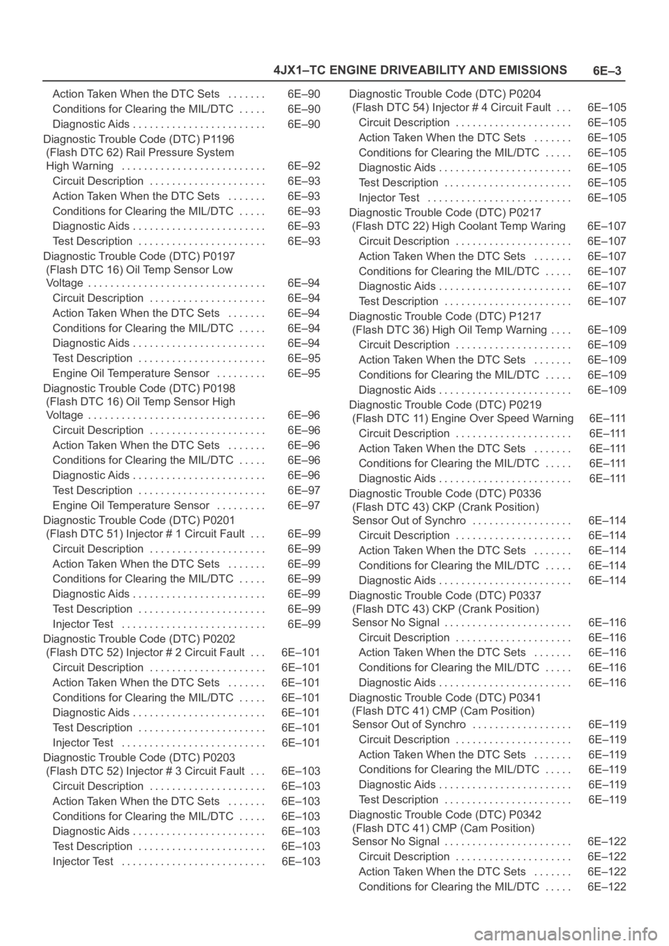
Diagnostic Trouble Code (DTC) P1196
(Flash DTC 62) Rail Pressure System
High Warning 6E–92. . . . . . . . . . . . . . . . . . . . . . . . . .
Circuit Description 6E–93. . . . . . . . . . . . . . . . . . . . .
Action Taken When the DTC Sets 6E–93. . . . . . .
Conditions for Clearing the MIL/DTC 6E–93. . . . .
Diagnostic Aids 6E–93. . . . . . . . . . . . . . . . . . . . . . . .
Test Description 6E–93. . . . . . . . . . . . . . . . . . . . . . .
Diagnostic Trouble Code (DTC) P0197
(Flash DTC 16) Oil Temp Sensor Low
Voltage 6E–94. . . . . . . . . . . . . . . . . . . . . . . . . . . . . . . .
Circuit Description 6E–94. . . . . . . . . . . . . . . . . . . . .
Action Taken When the DTC Sets 6E–94. . . . . . .
Conditions for Clearing the MIL/DTC 6E–94. . . . .
Diagnostic Aids 6E–94. . . . . . . . . . . . . . . . . . . . . . . .
Test Description 6E–95. . . . . . . . . . . . . . . . . . . . . . .
Engine Oil Temperature Sensor 6E–95. . . . . . . . .
Diagnostic Trouble Code (DTC) P0198
(Flash DTC 16) Oil Temp Sensor High
Voltage 6E–96. . . . . . . . . . . . . . . . . . . . . . . . . . . . . . . .
Circuit Description 6E–96. . . . . . . . . . . . . . . . . . . . .
Action Taken When the DTC Sets 6E–96. . . . . . .
Conditions for Clearing the MIL/DTC 6E–96. . . . .
Diagnostic Aids 6E–96. . . . . . . . . . . . . . . . . . . . . . . .
Test Description 6E–97. . . . . . . . . . . . . . . . . . . . . . .
Engine Oil Temperature Sensor 6E–97. . . . . . . . .
Diagnostic Trouble Code (DTC) P0201
(Flash DTC 51) Injector # 1 Circuit Fault 6E–99. . .
Circuit Description 6E–99. . . . . . . . . . . . . . . . . . . . .
Action Taken When the DTC Sets 6E–99. . . . . . .
Conditions for Clearing the MIL/DTC 6E–99. . . . .
Diagnostic Aids 6E–99. . . . . . . . . . . . . . . . . . . . . . . .
Test Description 6E–99. . . . . . . . . . . . . . . . . . . . . . .
Injector Test 6E–99. . . . . . . . . . . . . . . . . . . . . . . . . .
Diagnostic Trouble Code (DTC) P0202
(Flash DTC 52) Injector # 2 Circuit Fault 6E–101. . .
Circuit Description 6E–101. . . . . . . . . . . . . . . . . . . . .
Action Taken When the DTC Sets 6E–101. . . . . . .
Conditions for Clearing the MIL/DTC 6E–101. . . . .
Diagnostic Aids 6E–101. . . . . . . . . . . . . . . . . . . . . . . .
Test Description 6E–101. . . . . . . . . . . . . . . . . . . . . . .
Injector Test 6E–101. . . . . . . . . . . . . . . . . . . . . . . . . .
Diagnostic Trouble Code (DTC) P0203
(Flash DTC 52) Injector # 3 Circuit Fault 6E–103. . .
Circuit Description 6E–103. . . . . . . . . . . . . . . . . . . . .
Action Taken When the DTC Sets 6E–103. . . . . . .
Conditions for Clearing the MIL/DTC 6E–103. . . . .
Diagnostic Aids 6E–103. . . . . . . . . . . . . . . . . . . . . . . .
Test Description 6E–103. . . . . . . . . . . . . . . . . . . . . . .
Injector Test 6E–103. . . . . . . . . . . . . . . . . . . . . . . . . . Diagnostic Trouble Code (DTC) P0204
(Flash DTC 54) Injector # 4 Circuit Fault 6E–105
. . .
Circuit Description 6E–105. . . . . . . . . . . . . . . . . . . . .
Action Taken When the DTC Sets 6E–105. . . . . . .
Conditions for Clearing the MIL/DTC 6E–105. . . . .
Diagnostic Aids 6E–105. . . . . . . . . . . . . . . . . . . . . . . .
Test Description 6E–105. . . . . . . . . . . . . . . . . . . . . . .
Injector Test 6E–105. . . . . . . . . . . . . . . . . . . . . . . . . .
Diagnostic Trouble Code (DTC) P0217
(Flash DTC 22) High Coolant Temp Waring 6E–107
Circuit Description 6E–107. . . . . . . . . . . . . . . . . . . . .
Action Taken When the DTC Sets 6E–107. . . . . . .
Conditions for Clearing the MIL/DTC 6E–107. . . . .
Diagnostic Aids 6E–107. . . . . . . . . . . . . . . . . . . . . . . .
Test Description 6E–107. . . . . . . . . . . . . . . . . . . . . . .
Diagnostic Trouble Code (DTC) P1217
(Flash DTC 36) High Oil Temp Warning 6E–109. . . .
Circuit Description 6E–109. . . . . . . . . . . . . . . . . . . . .
Action Taken When the DTC Sets 6E–109. . . . . . .
Conditions for Clearing the MIL/DTC 6E–109. . . . .
Diagnostic Aids 6E–109. . . . . . . . . . . . . . . . . . . . . . . .
Diagnostic Trouble Code (DTC) P0219
(Flash DTC 11) Engine Over Speed Warning 6E–111
Circuit Description 6E–111. . . . . . . . . . . . . . . . . . . . .
Action Taken When the DTC Sets 6E–111. . . . . . .
Conditions for Clearing the MIL/DTC 6E–111. . . . .
Diagnostic Aids 6E–111. . . . . . . . . . . . . . . . . . . . . . . .
Diagnostic Trouble Code (DTC) P0336
(Flash DTC 43) CKP (Crank Position)
Sensor Out of Synchro 6E–114. . . . . . . . . . . . . . . . . .
Circuit Description 6E–114. . . . . . . . . . . . . . . . . . . . .
Action Taken When the DTC Sets 6E–114. . . . . . .
Conditions for Clearing the MIL/DTC 6E–114. . . . .
Diagnostic Aids 6E–114. . . . . . . . . . . . . . . . . . . . . . . .
Diagnostic Trouble Code (DTC) P0337
(Flash DTC 43) CKP (Crank Position)
Sensor No Signal 6E–116. . . . . . . . . . . . . . . . . . . . . . .
Circuit Description 6E–116. . . . . . . . . . . . . . . . . . . . .
Action Taken When the DTC Sets 6E–116. . . . . . .
Conditions for Clearing the MIL/DTC 6E–116. . . . .
Diagnostic Aids 6E–116. . . . . . . . . . . . . . . . . . . . . . . .
Diagnostic Trouble Code (DTC) P0341
(Flash DTC 41) CMP (Cam Position)
Sensor Out of Synchro 6E–119. . . . . . . . . . . . . . . . . .
Circuit Description 6E–119. . . . . . . . . . . . . . . . . . . . .
Action Taken When the DTC Sets 6E–119. . . . . . .
Conditions for Clearing the MIL/DTC 6E–119. . . . .
Diagnostic Aids 6E–119. . . . . . . . . . . . . . . . . . . . . . . .
Test Description 6E–119. . . . . . . . . . . . . . . . . . . . . . .
Diagnostic Trouble Code (DTC) P0342
(Flash DTC 41) CMP (Cam Position)
Sensor No Signal 6E–122. . . . . . . . . . . . . . . . . . . . . . .
Circuit Description 6E–122. . . . . . . . . . . . . . . . . . . . .
Action Taken When the DTC Sets 6E–122. . . . . . .
Conditions for Clearing the MIL/DTC 6E–122. . . . .
Page 1947 of 6000
6E–54
4JX1–TC ENGINE DRIVEABILITY AND EMISSIONS
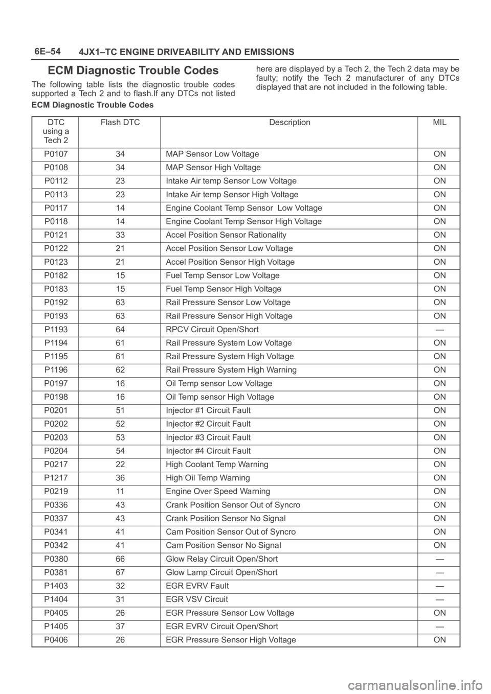
ECM Diagnostic Trouble Codes
The following table lists the diagnostic trouble codes
supported a Tech 2 and to flash.If any DTCs not listedhere are displayed by a Tech 2, the Tech 2 data may be
faulty; notify the Tech 2 manufacturer of any DTCs
displayed that are not included in the following table.
ECM Diagnostic Trouble Codes
DTC
using a
Te c h 2
Flash DTCDescriptionMIL
P010734MAP Sensor Low VoltageON
P010834MAP Sensor High VoltageON
P011223Intake Air temp Sensor Low VoltageON
P011323Intake Air temp Sensor High VoltageON
P011714Engine Coolant Temp Sensor Low VoltageON
P011814Engine Coolant Temp Sensor High VoltageON
P012133Accel Position Sensor RationalityON
P012221Accel Position Sensor Low VoltageON
P012321Accel Position Sensor High VoltageON
P018215Fuel Temp Sensor Low VoltageON
P018315Fuel Temp Sensor High VoltageON
P019263Rail Pressure Sensor Low VoltageON
P019363Rail Pressure Sensor High VoltageON
P119364RPCV Circuit Open/Short—
P119461Rail Pressure System Low VoltageON
P119561Rail Pressure System High VoltageON
P119662Rail Pressure System High WarningON
P019716Oil Temp sensor Low VoltageON
P019816Oil Temp sensor High VoltageON
P020151Injector #1 Circuit FaultON
P020252Injector #2 Circuit FaultON
P020353Injector #3 Circuit FaultON
P020454Injector #4 Circuit FaultON
P021722High Coolant Temp WarningON
P121736High Oil Temp WarningON
P021911Engine Over Speed WarningON
P033643Crank Position Sensor Out of SyncroON
P033743Crank Position Sensor No SignalON
P034141Cam Position Sensor Out of SyncroON
P034241Cam Position Sensor No SignalON
P038066Glow Relay Circuit Open/Short—
P038167Glow Lamp Circuit Open/Short—
P140332EGR EVRV Fault—
P140431EGR VSV Circuit—
P040526EGR Pressure Sensor Low VoltageON
P140537EGR EVRV Circuit Open/Short—
P040626EGR Pressure Sensor High VoltageON
Page 1985 of 6000
6E–92
4JX1–TC ENGINE DRIVEABILITY AND EMISSIONS
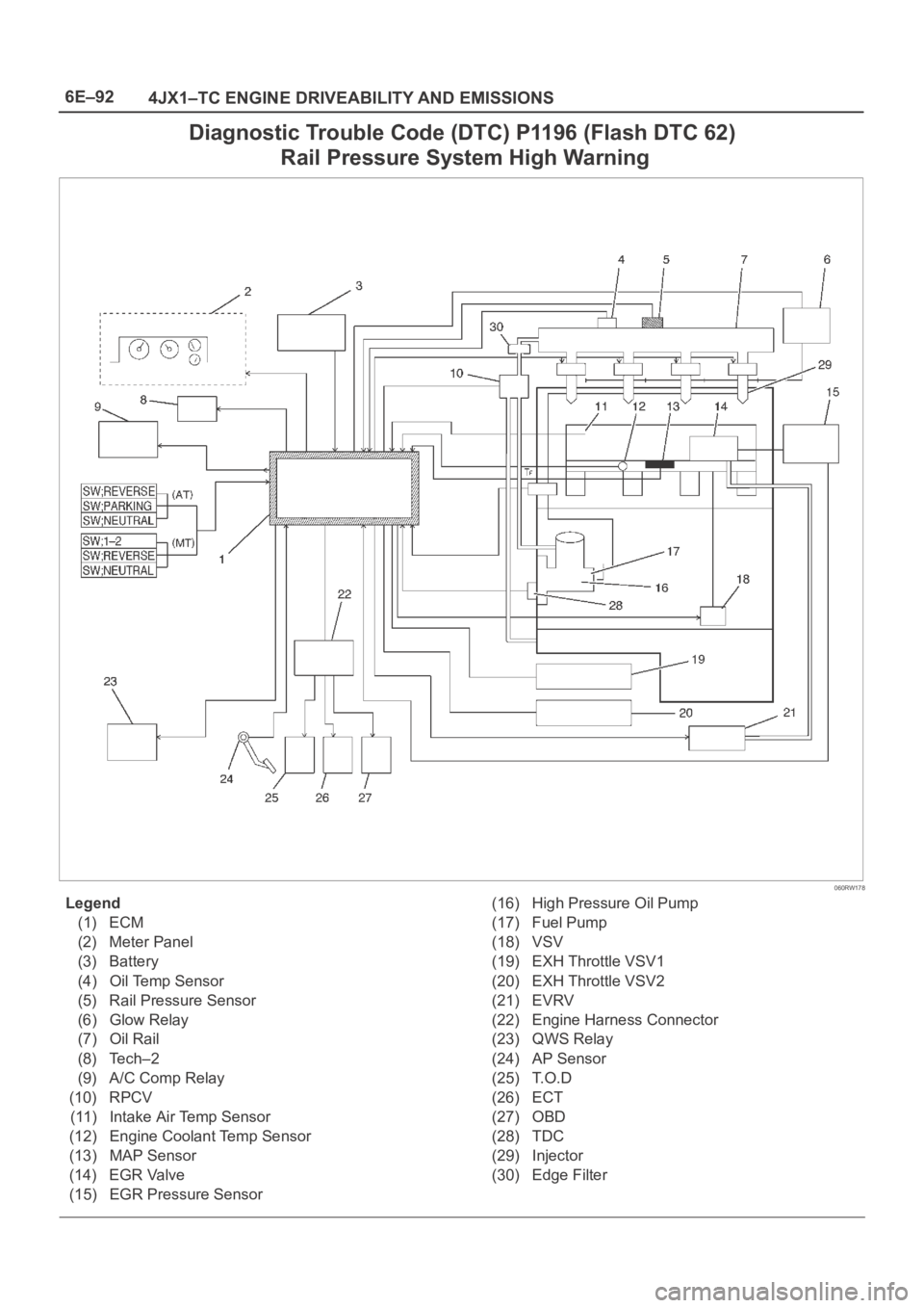
Diagnostic Trouble Code (DTC) P1196 (Flash DTC 62)
Rail Pressure System High Warning
060RW178
Legend
(1) ECM
(2) Meter Panel
(3) Battery
(4) Oil Temp Sensor
(5) Rail Pressure Sensor
(6) Glow Relay
(7) Oil Rail
(8) Tech–2
(9) A/C Comp Relay
(10) RPCV
(11) Intake Air Temp Sensor
(12) Engine Coolant Temp Sensor
(13) MAP Sensor
(14) EGR Valve
(15) EGR Pressure Sensor(16) High Pressure Oil Pump
(17) Fuel Pump
(18) VSV
(19) EXH Throttle VSV1
(20) EXH Throttle VSV2
(21) EVRV
(22) Engine Harness Connector
(23) QWS Relay
(24) AP Sensor
(25) T.O.D
(26) ECT
(27) OBD
(28) TDC
(29) Injector
(30) Edge Filter
Page 1986 of 6000
6E–93 4JX1–TC ENGINE DRIVEABILITY AND EMISSIONS
Circuit Description
The rail pressure control valve (RPCV) is built in the high
pressure oil circuit.
RPCV is an important device which is used to control oil
pressure in the HEUI system.
The circuit receives current through Engine 15A fuse from
the battery, current flowing in the order of RPCV.
Action Taken When the DTC Sets
The ECM will store conditions which were present
when the DTC was set as Freeze Frame and in the
Failure Records data.
Conditions for Clearing the MIL/DTC
DTC P1196 can be cleared by using the Tech 2 “Clear
Info” function or by disconnecting the ECM battery
feed.
Diagnostic Aids
Check for the following conditions:
Poor connection at ECM – Inspect harness connectors
for backed-out terminals, improper mating, broken
locks, improperly formed or damaged terminals, and
poor terminal-to-wire connection.
Damaged harness – Inspect the wiring harness for
damage. If the harness appears to be OK, observe the
Rail Pressure Control display on the Tech 2 while
moving connectors and wiring harnesses related to the
Rail Pressure Control. A change in the Rail Pressure
Control display will indicate the location of the fault.
If DTC P1196 cannot be duplicated, the information
included in the Failure Records data can be useful in
determining vehicle mileage since the DTC was last set.
If it is determined that the DTC occurs intermittently.
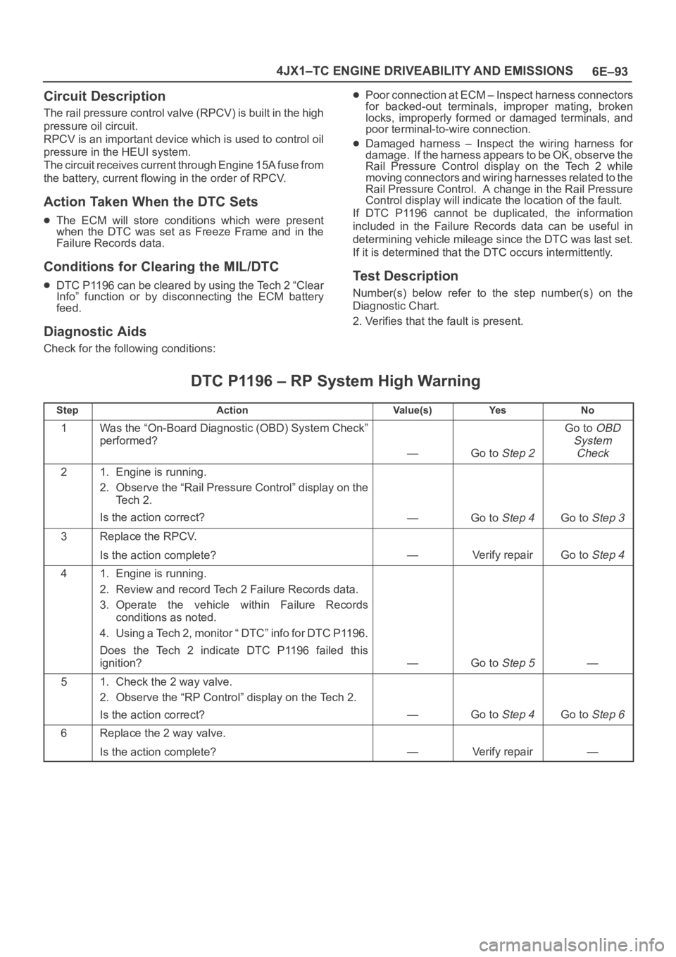
Test Description
Number(s) below refer to the step number(s) on the
Diagnostic Chart.
2. Verifies that the fault is present.
DTC P1196 – RP System High Warning
StepActionVa l u e ( s )Ye sNo
1Was the “On-Board Diagnostic (OBD) System Check”
performed?
—Go to Step 2
Go to OBD
System
Check
21. Engine is running.
2. Observe the “Rail Pressure Control” display on the
Te c h 2 .
Is the action correct?
—Go to Step 4Go to Step 3
3Replace the RPCV.
Is the action complete?
—Verify repairGo to Step 4
41. Engine is running.
2. Review and record Tech 2 Failure Records data.
3. Operate the vehicle within Failure Records
conditions as noted.
4. Using a Tech 2, monitor “ DTC” info for DTC P1196.
Does the Tech 2 indicate DTC P1196 failed this
ignition?
—Go to Step 5—
51. Check the 2 way valve.
2. Observe the “RP Control” display on the Tech 2.
Is the action correct?
—Go to Step 4Go to Step 6
6Replace the 2 way valve.
Is the action complete?
—Verify repair—
Page 2002 of 6000
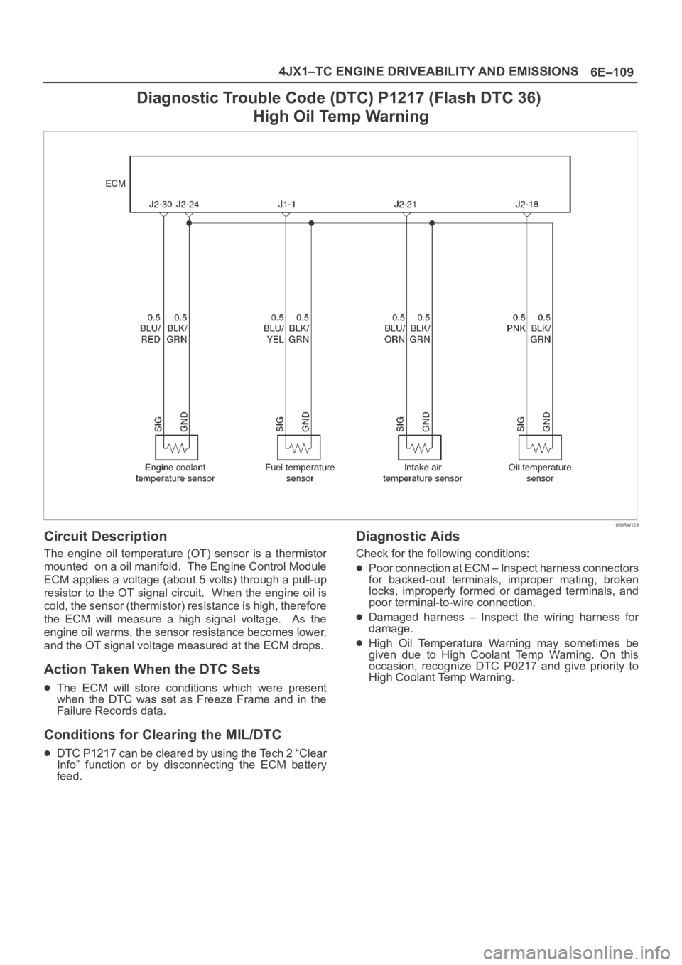
6E–109 4JX1–TC ENGINE DRIVEABILITY AND EMISSIONS
Diagnostic Trouble Code (DTC) P1217 (Flash DTC 36)
High Oil Temp Warning
060RW129
Circuit Description
The engine oil temperature (OT) sensor is a thermistor
mounted on a oil manifold. The Engine Control Module
ECM applies a voltage (about 5 volts) through a pull-up
resistor to the OT signal circuit. When the engine oil is
cold, the sensor (thermistor) resistance is high, therefore
the ECM will measure a high signal voltage. As the
engine oil warms, the sensor resistance becomes lower,
and the OT signal voltage measured at the ECM drops.
Action Taken When the DTC Sets
The ECM will store conditions which were present
when the DTC was set as Freeze Frame and in the
Failure Records data.
Conditions for Clearing the MIL/DTC
DTC P1217 can be cleared by using the Tech 2 “Clear
Info” function or by disconnecting the ECM battery
feed.
Diagnostic Aids
Check for the following conditions:
Poor connection at ECM – Inspect harness connectors
for backed-out terminals, improper mating, broken
locks, improperly formed or damaged terminals, and
poor terminal-to-wire connection.
Damaged harness – Inspect the wiring harness for
damage.
High Oil Temperature Warning may sometimes be
given due to High Coolant Temp Warning. On this
occasion, recognize DTC P0217 and give priority to
High Coolant Temp Warning.