1998 OPEL FRONTERA motor
[x] Cancel search: motorPage 1872 of 6000
ENGINE ELECTRICAL 6D – 5
STARTING SYTEM
GENERAL DESCRIPTION
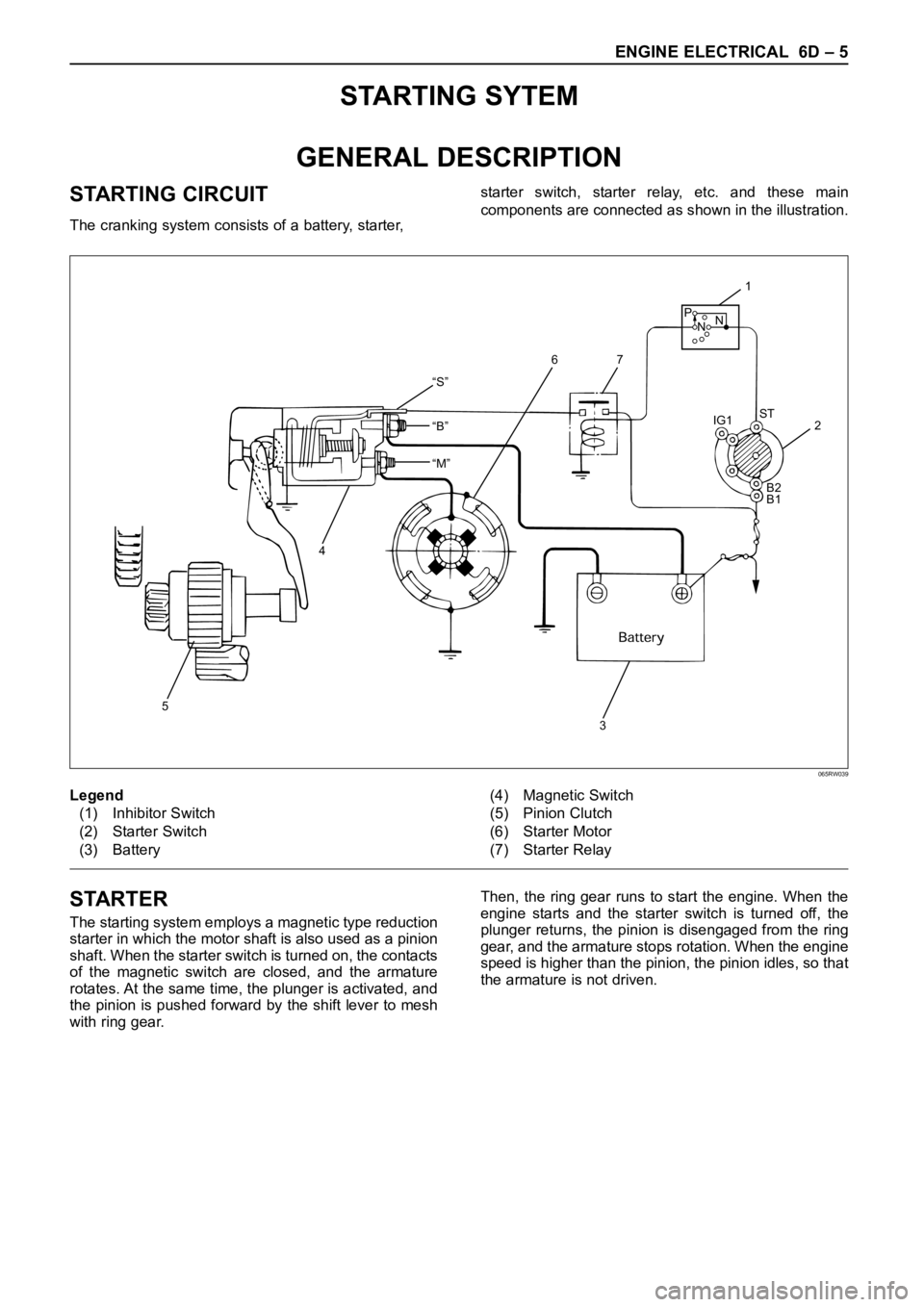
STARTING CIRCUIT
The cranking system consists of a battery, starter, starter switch, starter relay, etc. and these main
components are connected as shown in the illustration.
“S”
“B”
“M”
5
4
32 IG1ST
B2
B1
1
76
P
NN
Legend
(1) Inhibitor Switch
(2) Starter Switch
(3) Battery(4) Magnetic Switch
(5) Pinion Clutch
(6) Starter Motor
(7) Starter Relay
065RW039
STARTER
The starting system employs a magnetic type reduction
starter in which the motor shaft is also used as a pinion
shaft. When the starter switch is turned on, the contacts
of the magnetic switch are closed, and the armature
rotates. At the same time, the plunger is activated, and
the pinion is pushed forward by the shift lever to mesh
with ring gear.Then, the ring gear runs to start the engine. When the
engine starts and the starter switch is turned off, the
plunger returns, the pinion is disengaged from the ring
gear, and the armature stops rotation. When the engine
speed is higher than the pinion, the pinion idles, so that
the armature is not driven.
Page 1874 of 6000
ENGINE ELECTRICAL 6D – 7
ON-VEHICLE SERVICE
STARTER
REMOVAL
1 Battery ground cable
2 Remove the slave cylinder and bind with wire it to
the frame.
3 Disconnect the connector from terminals “B” and
“S”.
4. Remove mounting bolts
5. Remove starter assembly
INSTALLATION
1. Install starter assembly, tighten the fixing bolt and
nut to the specified torque.
Torque: 94 Nꞏm (9.6 kgꞏm/69 lb ft)
2. Reconnect the starter terminals.
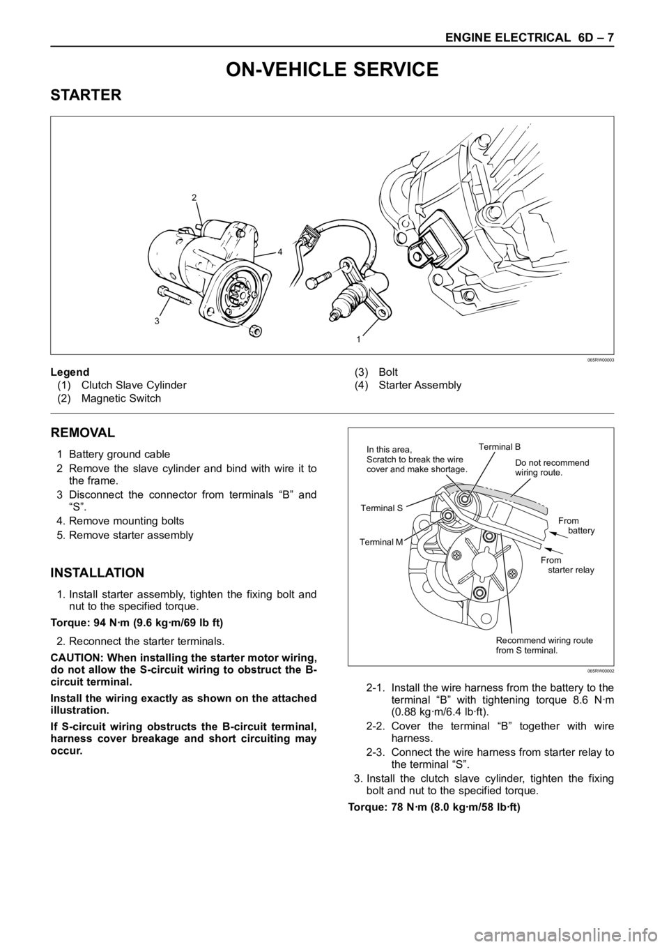
CAUTION: When installing the starter motor wiring,
do not allow the S-circuit wiring to obstruct the B-
circuit terminal.
Install the wiring exactly as shown on the attached
illustration.
If S-circuit wiring obstructs the B-circuit terminal,
harness cover breakage and short circuiting may
occur.2-1. Install the wire harness from the battery to the
terminal “B” with tightening torque 8.6 Nꞏm
(0.88 kgꞏm/6.4 lbꞏft).
2-2. Cover the terminal “B” together with wire
harness.
2-3. Connect the wire harness from starter relay to
the terminal “S”.
3. Install the clutch slave cylinder, tighten the fixing
bolt and nut to the specified torque.
Torque: 78 Nꞏm (8.0 kgꞏm/58 lbꞏft)
1
32
4
Legend
(1) Clutch Slave Cylinder
(2) Magnetic Switch(3) Bolt
(4) Starter Assembly
065RW00003
Do not recommend
wiring route.
Recommend wiring route
from S terminal.From
battery
From
starter relay Terminal B
Terminal MTerminal SIn this area,
Scratch to break the wire
cover and make shortage.
065RW00002
Page 1875 of 6000
6D – 8 ENGINE ELECTRICAL
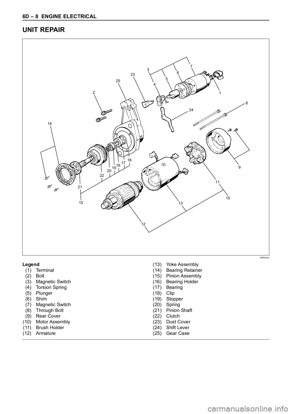
UNIT REPAIR
8
241 3
23
25
2
14
15 21222019181716
109
11
13
127
6
5
4
Legend
(1) Terminal
(2) Bolt
(3) Magnetic Switch
(4) Torsion Spring
(5) Plunger
(6) Shim
(7) Magnetic Switch
(8) Through Bolt
(9) Rear Cover
(10) Motor Assembly
(11) Brush Holder
(12) Armature(13) Yoke Assembly
(14) Bearing Retainer
(15) Pinion Assembly
(16) Bearing Holder
(17) Bearing
(18) Clip
(19) Stopper
(20) Spring
(21) Pinion Shaft
(22) Clutch
(23) Dust Cover
(24) Shift Lever
(25) Gear Case
065RW040
Page 1876 of 6000
ENGINE ELECTRICAL 6D – 9
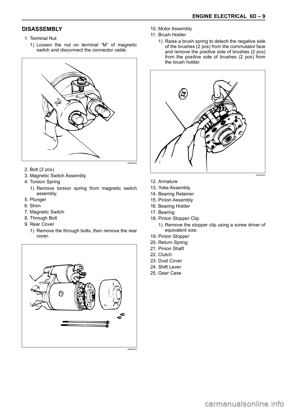
DISASSEMBLY
1. Terminal Nut
1) Loosen the nut on terminal “M” of magnetic
switch and disconnect the connector cable.
2. Bolt (2 pcs)
3. Magnetic Switch Assembly
4. Torsion Spring
1) Remove torsion spring from magnetic switch
assembly.
5. Plunger
6. Shim
7. Magnetic Switch
8. Through Bolt
9. Rear Cover
1) Remove the through bolts, then remove the rear
cover.10. Motor Assembly
11. Brush Holder
1) Raise a brush spring to detach the negative side
of the brushes (2 pcs) from the commutator face
and remove the positive side of brushes (2 pcs)
from the positive side of brushes (2 pcs) from
the brush holder.
12. Armature
13. Yoke Assembly
14. Bearing Retainer
15. Pinion Assembly
16. Bearing Holder
17. Bearing
18. Pinion Stopper Clip
1) Remove the stopper clip using a screw driver of
equivalent size.
19. Pinion Stopper
20. Return Spring
21. Pinion Shaft
22. Clutch
23. Dust Cover
24. Shift Lever
25. Gear Case
065RW044
065RW043
065RW042
Page 1897 of 6000
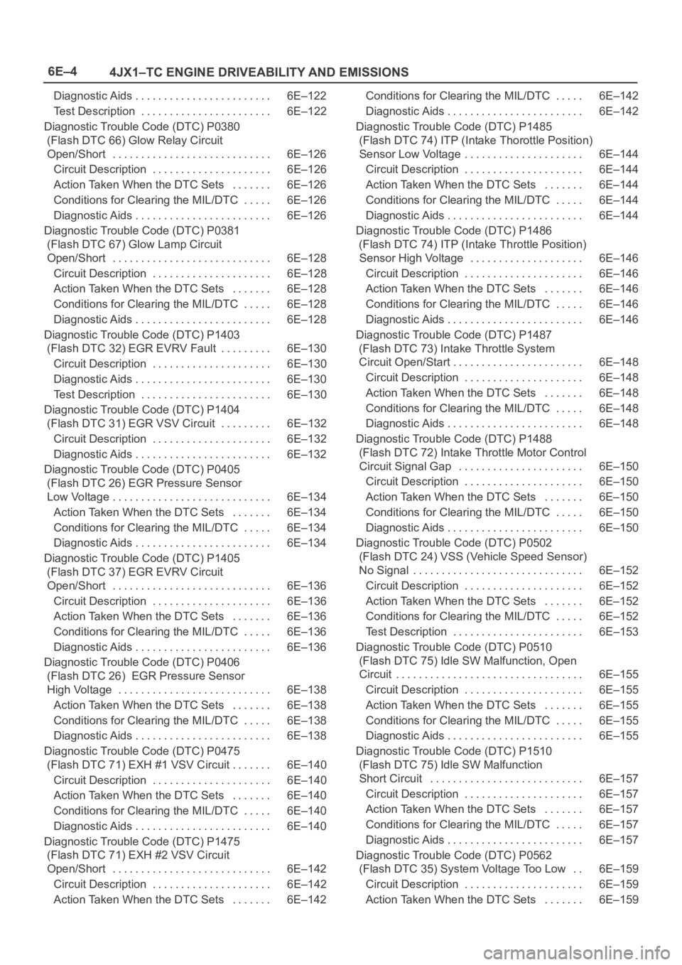
6E–4
4JX1–TC ENGINE DRIVEABILITY AND EMISSIONS
Diagnostic Aids 6E–122. . . . . . . . . . . . . . . . . . . . . . . .
Test Description 6E–122. . . . . . . . . . . . . . . . . . . . . . .
Diagnostic Trouble Code (DTC) P0380
(Flash DTC 66) Glow Relay Circuit
Open/Short 6E–126. . . . . . . . . . . . . . . . . . . . . . . . . . . .
Circuit Description 6E–126. . . . . . . . . . . . . . . . . . . . .
Action Taken When the DTC Sets 6E–126. . . . . . .
Conditions for Clearing the MIL/DTC 6E–126. . . . .
Diagnostic Aids 6E–126. . . . . . . . . . . . . . . . . . . . . . . .
Diagnostic Trouble Code (DTC) P0381
(Flash DTC 67) Glow Lamp Circuit
Open/Short 6E–128. . . . . . . . . . . . . . . . . . . . . . . . . . . .
Circuit Description 6E–128. . . . . . . . . . . . . . . . . . . . .
Action Taken When the DTC Sets 6E–128. . . . . . .
Conditions for Clearing the MIL/DTC 6E–128. . . . .
Diagnostic Aids 6E–128. . . . . . . . . . . . . . . . . . . . . . . .
Diagnostic Trouble Code (DTC) P1403
(Flash DTC 32) EGR EVRV Fault 6E–130. . . . . . . . .
Circuit Description 6E–130. . . . . . . . . . . . . . . . . . . . .
Diagnostic Aids 6E–130. . . . . . . . . . . . . . . . . . . . . . . .
Test Description 6E–130. . . . . . . . . . . . . . . . . . . . . . .
Diagnostic Trouble Code (DTC) P1404
(Flash DTC 31) EGR VSV Circuit 6E–132. . . . . . . . .
Circuit Description 6E–132. . . . . . . . . . . . . . . . . . . . .
Diagnostic Aids 6E–132. . . . . . . . . . . . . . . . . . . . . . . .
Diagnostic Trouble Code (DTC) P0405
(Flash DTC 26) EGR Pressure Sensor
Low Voltage 6E–134. . . . . . . . . . . . . . . . . . . . . . . . . . . .
Action Taken When the DTC Sets 6E–134. . . . . . .
Conditions for Clearing the MIL/DTC 6E–134. . . . .
Diagnostic Aids 6E–134. . . . . . . . . . . . . . . . . . . . . . . .
Diagnostic Trouble Code (DTC) P1405
(Flash DTC 37) EGR EVRV Circuit
Open/Short 6E–136. . . . . . . . . . . . . . . . . . . . . . . . . . . .
Circuit Description 6E–136. . . . . . . . . . . . . . . . . . . . .
Action Taken When the DTC Sets 6E–136. . . . . . .
Conditions for Clearing the MIL/DTC 6E–136. . . . .
Diagnostic Aids 6E–136. . . . . . . . . . . . . . . . . . . . . . . .
Diagnostic Trouble Code (DTC) P0406
(Flash DTC 26) EGR Pressure Sensor
High Voltage 6E–138. . . . . . . . . . . . . . . . . . . . . . . . . . .
Action Taken When the DTC Sets 6E–138. . . . . . .
Conditions for Clearing the MIL/DTC 6E–138. . . . .
Diagnostic Aids 6E–138. . . . . . . . . . . . . . . . . . . . . . . .
Diagnostic Trouble Code (DTC) P0475
(Flash DTC 71) EXH #1 VSV Circuit 6E–140. . . . . . .
Circuit Description 6E–140. . . . . . . . . . . . . . . . . . . . .
Action Taken When the DTC Sets 6E–140. . . . . . .
Conditions for Clearing the MIL/DTC 6E–140. . . . .
Diagnostic Aids 6E–140. . . . . . . . . . . . . . . . . . . . . . . .
Diagnostic Trouble Code (DTC) P1475
(Flash DTC 71) EXH #2 VSV Circuit
Open/Short 6E–142. . . . . . . . . . . . . . . . . . . . . . . . . . . .
Circuit Description 6E–142. . . . . . . . . . . . . . . . . . . . .
Action Taken When the DTC Sets 6E–142. . . . . . . Conditions for Clearing the MIL/DTC 6E–142. . . . .
Diagnostic Aids 6E–142. . . . . . . . . . . . . . . . . . . . . . . .
Diagnostic Trouble Code (DTC) P1485
(Flash DTC 74) ITP (Intake Thorottle Position)
Sensor Low Voltage 6E–144. . . . . . . . . . . . . . . . . . . . .
Circuit Description 6E–144. . . . . . . . . . . . . . . . . . . . .
Action Taken When the DTC Sets 6E–144. . . . . . .
Conditions for Clearing the MIL/DTC 6E–144. . . . .
Diagnostic Aids 6E–144. . . . . . . . . . . . . . . . . . . . . . . .
Diagnostic Trouble Code (DTC) P1486
(Flash DTC 74) ITP (Intake Throttle Position)
Sensor High Voltage 6E–146. . . . . . . . . . . . . . . . . . . .
Circuit Description 6E–146. . . . . . . . . . . . . . . . . . . . .
Action Taken When the DTC Sets 6E–146. . . . . . .
Conditions for Clearing the MIL/DTC 6E–146. . . . .
Diagnostic Aids 6E–146. . . . . . . . . . . . . . . . . . . . . . . .
Diagnostic Trouble Code (DTC) P1487
(Flash DTC 73) Intake Throttle System
Circuit Open/Start 6E–148. . . . . . . . . . . . . . . . . . . . . . .
Circuit Description 6E–148. . . . . . . . . . . . . . . . . . . . .
Action Taken When the DTC Sets 6E–148. . . . . . .
Conditions for Clearing the MIL/DTC 6E–148. . . . .
Diagnostic Aids 6E–148. . . . . . . . . . . . . . . . . . . . . . . .
Diagnostic Trouble Code (DTC) P1488
(Flash DTC 72) Intake Throttle Motor Control
Circuit Signal Gap 6E–150. . . . . . . . . . . . . . . . . . . . . .
Circuit Description 6E–150. . . . . . . . . . . . . . . . . . . . .
Action Taken When the DTC Sets 6E–150. . . . . . .
Conditions for Clearing the MIL/DTC 6E–150. . . . .
Diagnostic Aids 6E–150. . . . . . . . . . . . . . . . . . . . . . . .
Diagnostic Trouble Code (DTC) P0502
(Flash DTC 24) VSS (Vehicle Speed Sensor)
No Signal 6E–152. . . . . . . . . . . . . . . . . . . . . . . . . . . . . .
Circuit Description 6E–152. . . . . . . . . . . . . . . . . . . . .
Action Taken When the DTC Sets 6E–152. . . . . . .
Conditions for Clearing the MIL/DTC 6E–152. . . . .
Test Description 6E–153. . . . . . . . . . . . . . . . . . . . . . .
Diagnostic Trouble Code (DTC) P0510
(Flash DTC 75) Idle SW Malfunction, Open
Circuit 6E–155. . . . . . . . . . . . . . . . . . . . . . . . . . . . . . . . .
Circuit Description 6E–155. . . . . . . . . . . . . . . . . . . . .
Action Taken When the DTC Sets 6E–155. . . . . . .
Conditions for Clearing the MIL/DTC 6E–155. . . . .
Diagnostic Aids 6E–155. . . . . . . . . . . . . . . . . . . . . . . .
Diagnostic Trouble Code (DTC) P1510
(Flash DTC 75) Idle SW Malfunction
Short Circuit 6E–157. . . . . . . . . . . . . . . . . . . . . . . . . . .
Circuit Description 6E–157. . . . . . . . . . . . . . . . . . . . .
Action Taken When the DTC Sets 6E–157. . . . . . .
Conditions for Clearing the MIL/DTC 6E–157. . . . .
Diagnostic Aids 6E–157. . . . . . . . . . . . . . . . . . . . . . . .
Diagnostic Trouble Code (DTC) P0562
(Flash DTC 35) System Voltage Too Low 6E–159. .
Circuit Description 6E–159. . . . . . . . . . . . . . . . . . . . .
Action Taken When the DTC Sets 6E–159. . . . . . .
Page 1912 of 6000
6E–19 4JX1–TC ENGINE DRIVEABILITY AND EMISSIONS
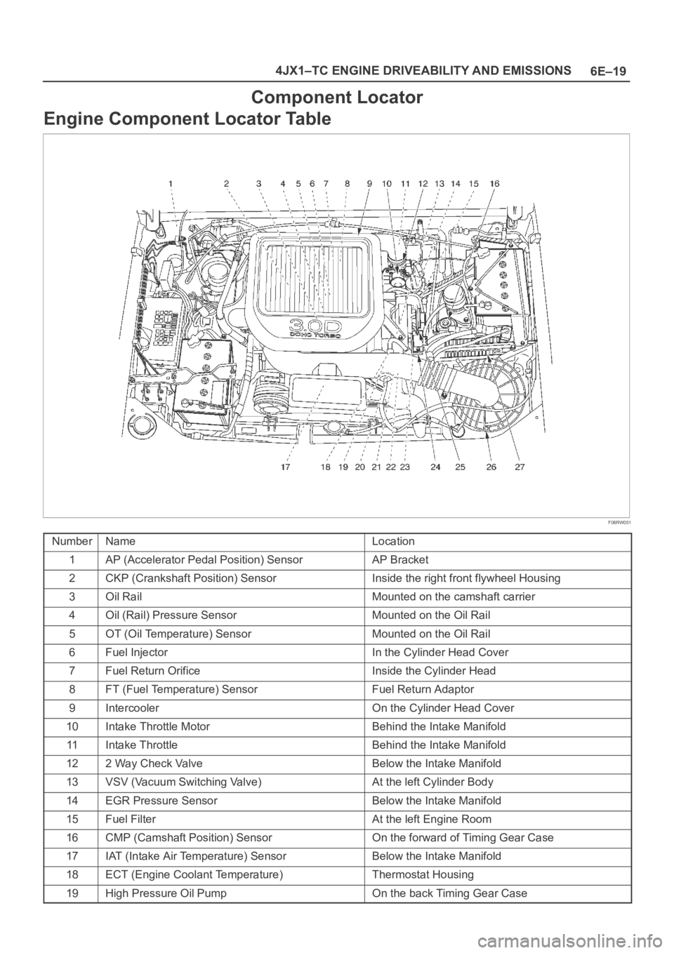
Component Locator
Engine Component Locator Table
F06RW051
NumberNameLocation
1AP (Accelerator Pedal Position) SensorAP Bracket
2CKP (Crankshaft Position) SensorInside the right front flywheel Housing
3Oil RailMounted on the camshaft carrier
4Oil (Rail) Pressure SensorMounted on the Oil Rail
5OT (Oil Temperature) SensorMounted on the Oil Rail
6Fuel InjectorIn the Cylinder Head Cover
7Fuel Return OrificeInside the Cylinder Head
8FT (Fuel Temperature) SensorFuel Return Adaptor
9IntercoolerOn the Cylinder Head Cover
10Intake Throttle MotorBehind the Intake Manifold
11Intake ThrottleBehind the Intake Manifold
122 Way Check ValveBelow the Intake Manifold
13VSV (Vacuum Switching Valve)At the left Cylinder Body
14EGR Pressure SensorBelow the Intake Manifold
15Fuel FilterAt the left Engine Room
16CMP (Camshaft Position) SensorOn the forward of Timing Gear Case
17IAT (Intake Air Temperature) SensorBelow the Intake Manifold
18ECT (Engine Coolant Temperature)Thermostat Housing
19High Pressure Oil PumpOn the back Timing Gear Case
Page 1924 of 6000
6E–31 4JX1–TC ENGINE DRIVEABILITY AND EMISSIONS
060RW120
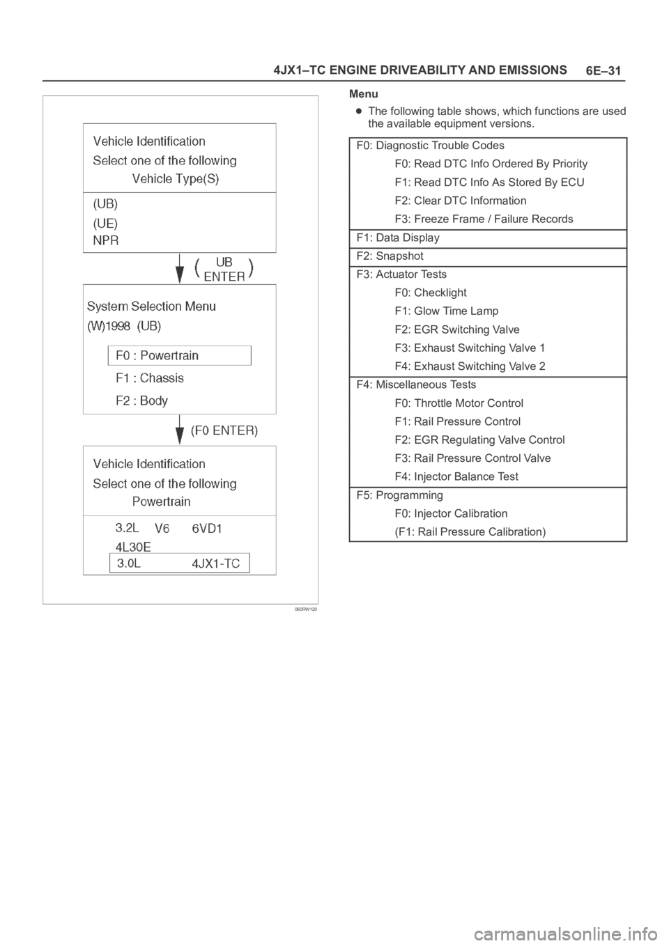
Menu
The following table shows, which functions are used
the available equipment versions.
F0: Diagnostic Trouble Codes
F0: Read DTC Info Ordered By Priority
F1: Read DTC Info As Stored By ECU
F2: Clear DTC Information
F3: Freeze Frame / Failure Records
F1: Data Display
F2: Snapshot
F3: Actuator Tests
F0: Checklight
F1: Glow Time Lamp
F2: EGR Switching Valve
F3: Exhaust Switching Valve 1
F4: Exhaust Switching Valve 2
F4: Miscellaneous Tests
F0: Throttle Motor Control
F1: Rail Pressure Control
F2: EGR Regulating Valve Control
F3: Rail Pressure Control Valve
F4: Injector Balance Test
F5: Programming
F0: Injector Calibration
(F1: Rail Pressure Calibration)
Page 1933 of 6000
6E–40
4JX1–TC ENGINE DRIVEABILITY AND EMISSIONS
MAP Sensor
CMP Sensor
CKP Sensor
EGR Pressure Sensor
EGR VSV
RPCV
IAT Sensor
Intake Throttle Motor
Fuel Temperature Sensor
Oil Temperature Sensor
Rail Pressure Sensor
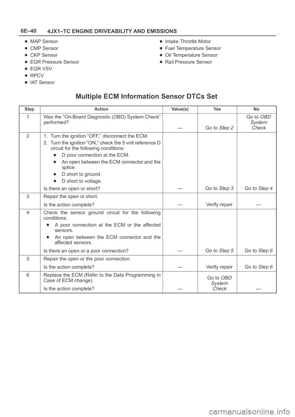
Multiple ECM Information Sensor DTCs Set
StepActionVa l u e ( s )Ye sNo
1Was the “On-Board Diagnostic (OBD) System Check”
performed?
—Go to Step 2
Go to OBD
System
Check
21. Turn the ignition “OFF,” disconnect the ECM.
2. Turn the ignition “ON,” check the 5 volt reference D
circuit for the following conditions:
D poor connection at the ECM.
An open between the ECM connector and the
splice.
D short to ground.
D short to voltage.
Is there an open or short?
—Go to Step 3Go to Step 4
3Repair the open or short.
Is the action complete?
—Verify repair—
4Check the sensor ground circuit for the following
conditions:
A poor connection at the ECM or the affected
sensors.
An open between the ECM connector and the
affected sensors.
Is there an open or a poor connection?
—Go to Step 5Go to Step 6
5Repair the open or the poor connection.
Is the action complete?
—Verify repairGo to Step 6
6Replace the ECM (Refer to the Data Programming in
Case of ECM change).
Is the action complete?
—
Go to OBD
System
Check
—