1998 OPEL FRONTERA motor
[x] Cancel search: motorPage 2194 of 6000
7A–40
AUTOMATIC TRANSMISSION (4L30–E)
Valve Body Assembly (Adapter Case)
Removal
1. Raise the vehicle and support it on jack stands.
2. Disconnect battery ground cable.
3. Drain fluid.
4. Remove transfer and exhaust protectors.
5. Remove exhaust pipe and disconnect oxygen sensor
connector.
6. Remove twelve 10 mm adapter case oil pan fixing
screws, adapter case oil pan, and gasket.
NOTE: Oil pan still contains transmission fluid. Place a
large drain container under the oil pan.
Drain the fluid carefully.
7. Disconnect wiring harness from force motor solenoid
and converter clutch solenoid. Pull only on
connectors, not on wiring harness.
8. Remove seven 13 mm screws from adapter case
valve body assembly, then remove transfer plate, two
gaskets, and adapter case valve body.
Installation
1. Inspect electrical 5 pin connector and seal of adapter
case. Replace if necessary.2. Install gasket, transfer plate, and gasket.
3. Install adapter case valve body and seven 13 mm
screws. Tighten the screws to the specified torque.
To r q u e : 2 0 N
m (2.0 kgꞏm/15 lb ft)
4. Connect wiring harness assembly to converter clutch
solenoid and force motor.
5. Install oil pan gasket, oil pan, and twelve 10 mm
screws. Tighten the screws to the specified torque.
To r q u e : 11 N
m (1.1 kgꞏm/96 lb in)
6. Install exhaust pipe and connect oxygen sensor
connector. Tighten the bolts to the specified torque.
Exhaust pipe flange bolt torque:
43 N
m(4.4kgꞏm/32lbft)
7. Install transfer and exhaust protectors. Tighten the
bolts to the specified torque.
To r q u e : 3 7 N
m(3.8kgꞏm/27lbft)
8. Fill transmission through the overfill screw hole of oil
pan, using ATF DEXRON
–III. Refer to Changing
Transmission Fluid in this section.
9. Connect battery ground cable.
Powertrain Control Module (PCM)
Removal
1. Disconnect battery ground cable.
2. Remove front console.
3. Disconnect PCM wiring harness connectors from
PCM.
4. Remove three PCM retaining screws.
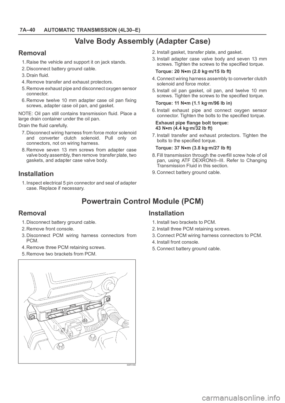
5. Remove two brackets from PCM.
826RV006
Installation
1. Install two brackets to PCM.
2. Install three PCM retaining screws.
3. Connect PCM wiring harness connectors to PCM.
4. Install front console.
5. Connect battery ground cable.
Page 2195 of 6000
7A–41 AUTOMATIC TRANSMISSION (4L30–E)
Speed Sensor (Extension Housing)
Removal
1. Disconnect battery ground cable.
2. Remove front console.
3. Remove selector lever assembly.
4. Disconnect speed sensor harness connector from
speed sensor.
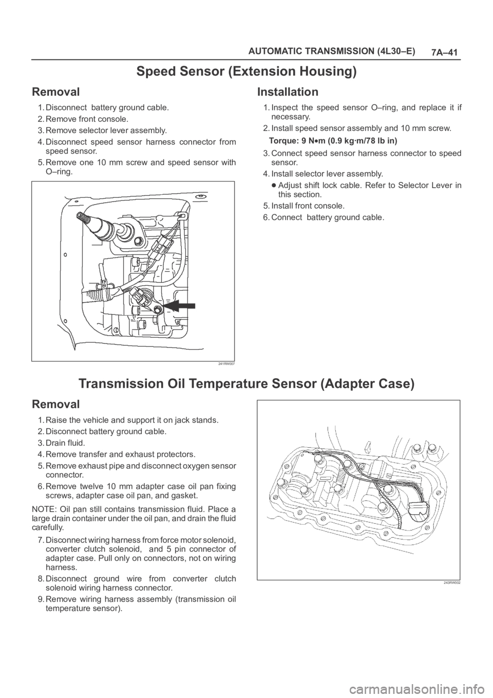
5. Remove one 10 mm screw and speed sensor with
O–ring.
241RW007
Installation
1. Inspect the speed sensor O–ring, and replace it if
necessary.
2. Install speed sensor assembly and 10 mm screw.
To r q u e : 9 N
m (0.9 kgꞏm/78 lb in)
3. Connect speed sensor harness connector to speed
sensor.
4. Install selector lever assembly.
Adjust shift lock cable. Refer to Selector Lever in
this section.
5. Install front console.
6. Connect battery ground cable.
Transmission Oil Temperature Sensor (Adapter Case)
Removal
1. Raise the vehicle and support it on jack stands.
2. Disconnect battery ground cable.
3. Drain fluid.
4. Remove transfer and exhaust protectors.
5. Remove exhaust pipe and disconnect oxygen sensor
connector.
6. Remove twelve 10 mm adapter case oil pan fixing
screws, adapter case oil pan, and gasket.
NOTE: Oil pan still contains transmission fluid. Place a
large drain container under the oil pan, and drain the fluid
carefully.
7. Disconnect wiring harness from force motor solenoid,
converter clutch solenoid, and 5 pin connector of
adapter case. Pull only on connectors, not on wiring
harness.
8. Disconnect ground wire from converter clutch
solenoid wiring harness connector.
9. Remove wiring harness assembly (transmission oil
temperature sensor).
243RW002
Page 2196 of 6000
7A–42
AUTOMATIC TRANSMISSION (4L30–E)
Installation
1. Connect ground wire to converter clutch solenoid
wiring harness connector of the wiring harness
assembly.
2. Install wiring harness assembly to converter clutch
solenoid, force motor, and 5 pin connector of adapter
case.
3. Install oil pan gasket, oil pan, and twelve 10 mm fixing
screws. Tighten the screws to the specified torque.
Torque: 11 N
m (1.1 kgꞏm/96 lb in)4. Install exhaust pipe and connect oxygen sensor
connector. Tighten the bolts to the specified torque.
Exhaust pipe flange bolt torque:
43 N
m(4.4kgꞏm/32lbft)
5. Install transfer and exhaust protectors. Tighten the
bolts to the specified torque.
To r q u e : 3 7 N
m (3.8 kgꞏm/27 lb ft)
6. Fill transmission through the overfill screw hole of oil
pan, using ATF DEXRON
–III.
Refer to Changing Transmission Fluid in this section.
7. Connect battery ground cable.
Front Oil Seal (Converter Housing)
Removal
1. Remove transmission assembly with transfer case
from the vehicle. Refer to Transmission (with Transfer
Case) in this section.
2. Remove torque converter from converter housing.
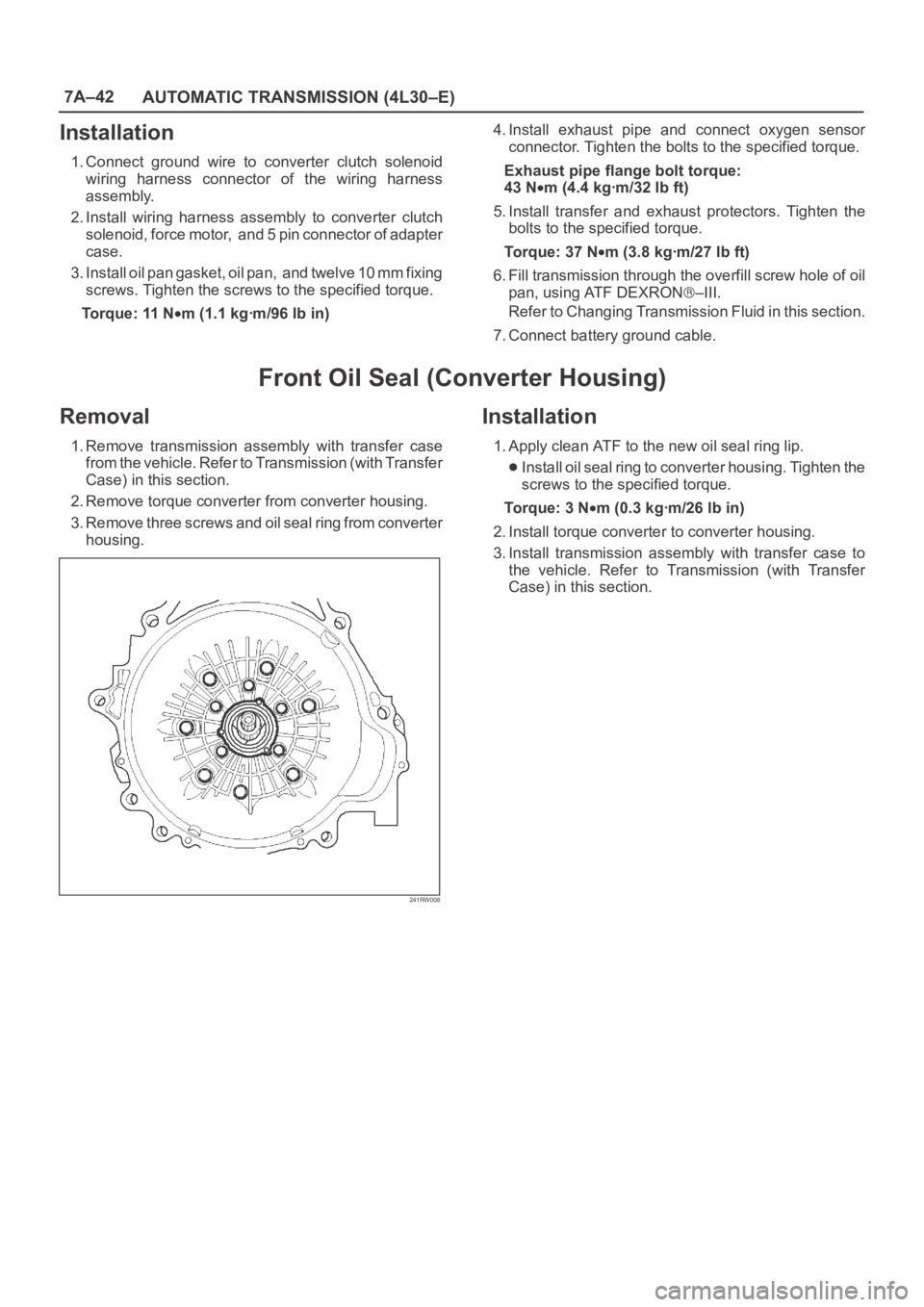
3. Remove three screws and oil seal ring from converter
housing.
241RW008
Installation
1. Apply clean ATF to the new oil seal ring lip.
Install oil seal ring to converter housing. Tighten the
screws to the specified torque.
To r q u e : 3 N
m (0.3 kgꞏm/26 lb in)
2. Install torque converter to converter housing.
3. Install transmission assembly with transfer case to
the vehicle. Refer to Transmission (with Transfer
Case) in this section.
Page 2210 of 6000
7A–56
AUTOMATIC TRANSMISSION (4L30–E)
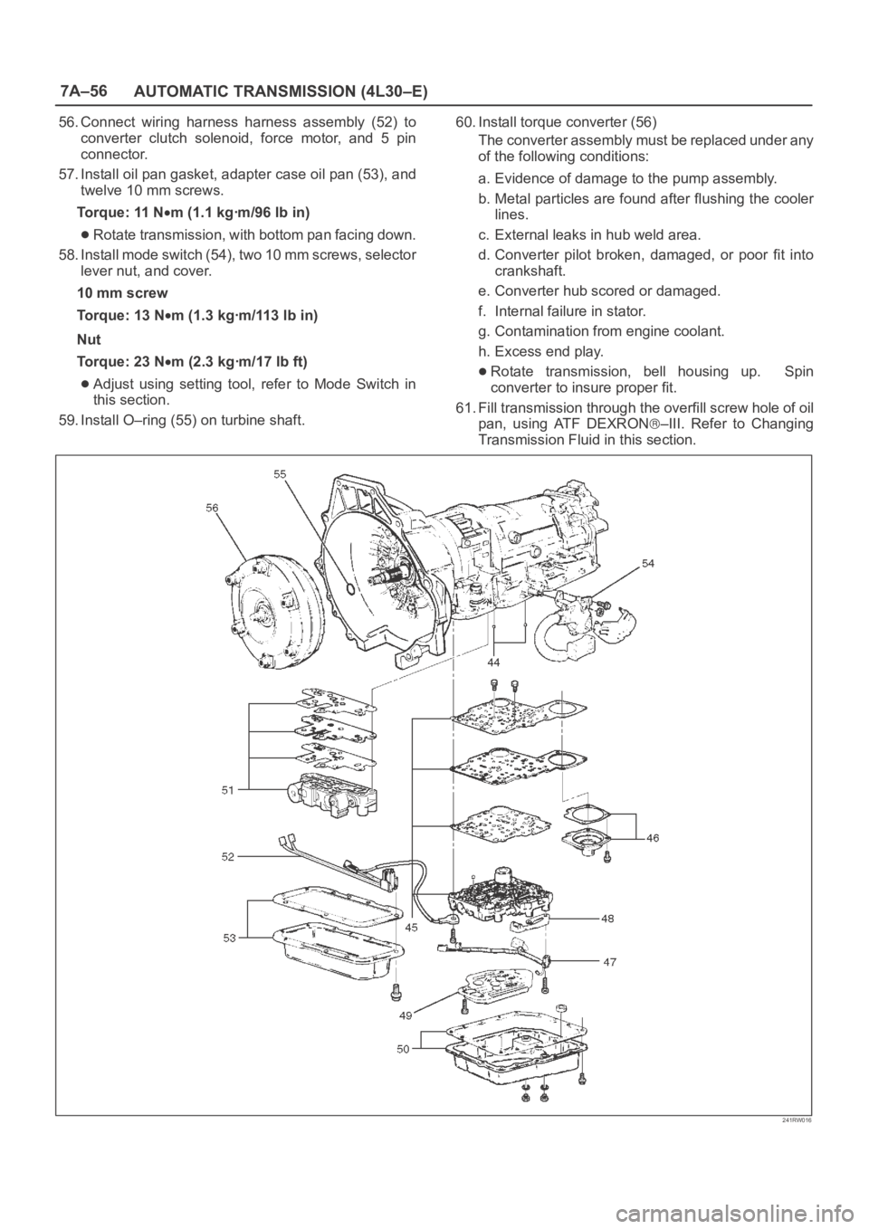
56. Connect wiring harness harness assembly (52) to
converter clutch solenoid, force motor, and 5 pin
connector.
57. Install oil pan gasket, adapter case oil pan (53), and
twelve 10 mm screws.
Torque: 11 N
m (1.1 kgꞏm/96 lb in)
Rotate transmission, with bottom pan facing down.
58. Install mode switch (54), two 10 mm screws, selector
lever nut, and cover.
10 mm screw
Torque: 13 N
m (1.3 kgꞏm/113 lb in)
Nut
Torque: 23 N
m (2.3 kgꞏm/17 lb ft)
Adjust using setting tool, refer to Mode Switch in
this section.
59. Install O–ring (55) on turbine shaft.60. Install torque converter (56)
The converter assembly must be replaced under any
of the following conditions:
a. Evidence of damage to the pump assembly.
b. Metal particles are found after flushing the cooler
lines.
c. External leaks in hub weld area.
d. Converter pilot broken, damaged, or poor fit into
crankshaft.
e. Converter hub scored or damaged.
f. Internal failure in stator.
g. Contamination from engine coolant.
h. Excess end play.Rotate transmission, bell housing up. Spin
converter to insure proper fit.
61. Fill transmission through the overfill screw hole of oil
pan, using ATF DEXRON
–III. Refer to Changing
Transmission Fluid in this section.
241RW016
Page 2215 of 6000
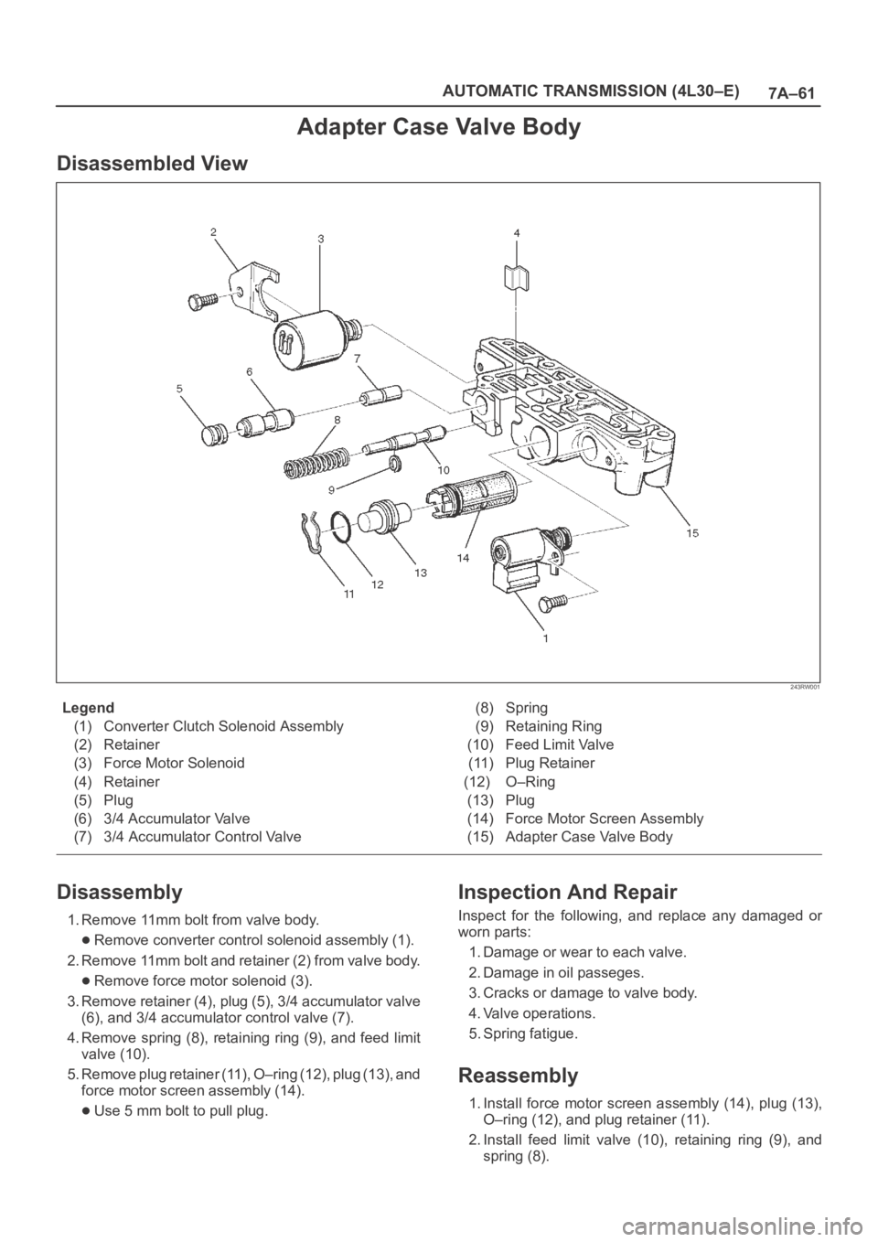
7A–61 AUTOMATIC TRANSMISSION (4L30–E)
Adapter Case Valve Body
Disassembled View
243RW001
Legend
(1) Converter Clutch Solenoid Assembly
(2) Retainer
(3) Force Motor Solenoid
(4) Retainer
(5) Plug
(6) 3/4 Accumulator Valve
(7) 3/4 Accumulator Control Valve(8) Spring
(9) Retaining Ring
(10) Feed Limit Valve
(11) Plug Retainer
(12) O–Ring
(13) Plug
(14) Force Motor Screen Assembly
(15) Adapter Case Valve Body
Disassembly
1. Remove 11mm bolt from valve body.
Remove converter control solenoid assembly (1).
2. Remove 11mm bolt and retainer (2) from valve body.
Remove force motor solenoid (3).
3. Remove retainer (4), plug (5), 3/4 accumulator valve
(6), and 3/4 accumulator control valve (7).
4. Remove spring (8), retaining ring (9), and feed limit
valve (10).
5. Remove plug retainer (11), O–ring (12), plug (13), and
force motor screen assembly (14).
Use 5 mm bolt to pull plug.
Inspection And Repair
Inspect for the following, and replace any damaged or
worn parts:
1. Damage or wear to each valve.
2. Damage in oil passeges.
3. Cracks or damage to valve body.
4. Valve operations.
5. Spring fatigue.
Reassembly
1. Install force motor screen assembly (14), plug (13),
O–ring (12), and plug retainer (11).
2. Install feed limit valve (10), retaining ring (9), and
spring (8).
Page 2216 of 6000
7A–62
AUTOMATIC TRANSMISSION (4L30–E)
3. Install 3/4 accumulator control valve (7), 3/4
accumulator valve (6), plug (5), and retainer (4).
4. Install force motor solenoid (3).
Place solenoid terminals pointing towards mating
face.
Install retainer (2) and bolt.
Torque: 10 N
m (1.0 kgꞏm/87 lb in)
5. Install converter clutch solenoid assembly with two
O–rings (1) to valve body.
Install bolt.
Torque: 10 N
m (1.0 kgꞏm/87 lb in)
Page 2242 of 6000
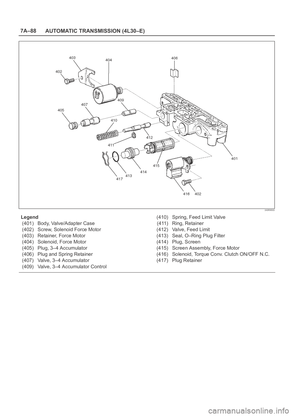
7A–88
AUTOMATIC TRANSMISSION (4L30–E)
243RW003
Legend
(401) Body, Valve/Adapter Case
(402) Screw, Solenoid Force Motor
(403) Retainer, Force Motor
(404) Solenoid, Force Motor
(405) Plug, 3–4 Accumulator
(406) Plug and Spring Retainer
(407) Valve, 3–4 Accumulator
(409) Valve, 3–4 Accumulator Control(410) Spring, Feed Limit Valve
(411) Ring, Retainer
(412) Valve, Feed Limit
(413) Seal, O–Ring Plug Filter
(414) Plug, Screen
(415) Screen Assembly, Force Motor
(416) Solenoid, Torque Conv. Clutch ON/OFF N.C.
(417) Plug Retainer
Page 2246 of 6000
TRANSMISSION CONTROL SYSTEM (4L30–E)7A1–1
TRANSMISSION
TRANSMISSION CONTROL SYSTEM (4L30–E)
CONTENTS
Service Precaution 7A1–2. . . . . . . . . . . . . . . . . . . . . .
General Description 7A1–2. . . . . . . . . . . . . . . . . . . . .
Shift Control 7A1–6. . . . . . . . . . . . . . . . . . . . . . . . . .
Band Apply Control 7A1–6. . . . . . . . . . . . . . . . . . . .
Torque Converter Clutch Control 7A1–6. . . . . . . . .
Line Pressure Control 7A1–6. . . . . . . . . . . . . . . . . .
On–Board Diagnostic System 7A1–6. . . . . . . . . . .
Fail Safe Mechanism 7A1–6. . . . . . . . . . . . . . . . . . .
Torque Management Control 7A1–6. . . . . . . . . . . .
ATF Warning Control 7A1–6. . . . . . . . . . . . . . . . . . .
ABS Control (If equipped) 7A1–6. . . . . . . . . . . . . .
Winter Drive Mode 7A1–9. . . . . . . . . . . . . . . . . . . . .
Backup Mode 7A1–9. . . . . . . . . . . . . . . . . . . . . . . . .
Functions of Input / Output Components 7A1–10. .
Diagnosis 7A1–11. . . . . . . . . . . . . . . . . . . . . . . . . . . . . .
Check Trans Indicator 7A1–11. . . . . . . . . . . . . . . . . .
Diagnostic Check 7A1–11. . . . . . . . . . . . . . . . . . . . . .
“Check Trans” Check 7A1–12. . . . . . . . . . . . . . . . . .
Tech2 OBD II Connection 7A1–13. . . . . . . . . . . . . . .
OBD II Diagnostic Management System 7A1–18. .
16 – Terminal Data Link Connector (DLC) 7A1–19.
Malfunction Indicator Lamp (MIL) 7A1–20. . . . . . . .
Types Of Diagnostic Trouble Codes
(DTCs) 7A1–20. . . . . . . . . . . . . . . . . . . . . . . . . . . . . .
Clear DTC 7A1–20. . . . . . . . . . . . . . . . . . . . . . . . . . . .
DTC Check 7A1–21. . . . . . . . . . . . . . . . . . . . . . . . . . .
PCM Precaution 7A1–21. . . . . . . . . . . . . . . . . . . . . . .
Information On PCM 7A1–21. . . . . . . . . . . . . . . . . . .
Intermittent Conditions 7A1–21. . . . . . . . . . . . . . . . .
Transmission And PCM Identification 7A1–22. . . . .
Diagnostic Trouble Code (DTC)
Identification 7A1–24. . . . . . . . . . . . . . . . . . . . . . . . .
DTC P0218 Transmission Fluid Over
Temperature 7A1–25. . . . . . . . . . . . . . . . . . . . . . . . . . . Conditions For Setting The DTC 7A1–25. . . . . . . . .
Action Taken When The DTC Sets 7A1–25. . . . . . .
Conditions For Clearing The DTC 7A1–25. . . . . . . .
Diagnostic Aids 7A1–25. . . . . . . . . . . . . . . . . . . . . . . .
Test Description 7A1–25. . . . . . . . . . . . . . . . . . . . . . .
DTC P0560 System Voltage Malfunction 7A1–27. . .
DTC P0705 Transmission Range Switch
(Mode Switch) Illegal Position 7A1–30. . . . . . . . . . . .
DTC P0706 Transmission Range Switch
(Mode Switch) Performance 7A1–33. . . . . . . . . . . . . .
DTC P0712 Transmission Fluid Temperature
(TFT) Sensor Circuit Low Input 7A1–36. . . . . . . . . . .
DTC P0713 Transmission Fluid Temperature
(TFT) Sensor Circuit High Input 7A1–39. . . . . . . . . . .
DTC P0719 TCC Brake Switch Circuit High
(Stuck On) 7A1–42. . . . . . . . . . . . . . . . . . . . . . . . . . . . .
DTC P0722 Transmission Output Speed
Sensor (OSS) Low Input 7A1–45. . . . . . . . . . . . . . . . .
DTC P0723 Transmission Output Speed
Sensor (OSS) Intermittent 7A1–48. . . . . . . . . . . . . . .
DTC P0730 Transmission Incorrect
Gear Ratio 7A1–51. . . . . . . . . . . . . . . . . . . . . . . . . . . . .
DTC P0748 Pressure Control Solenoid
(PCS) (Force Motor) Circuit Electrical 7A1–54. . . . .
DTC P0753 Shift Solenoid A Electrical 7A1–56. . . . .
DTC P0758 Shift Solenoid B Electrical 7A1–59. . . . .
DTC P1790 ROM Transmission Side Bad
Check Sum 7A1–63. . . . . . . . . . . . . . . . . . . . . . . . . . . .
DTC P1792 EEPROM Transmission Side
Bad Check Sum 7A1–64. . . . . . . . . . . . . . . . . . . . . . . .
DTC P1835 Kickdown Switch Always On 7A1–65. . .
DTC P1850 Brake Band Apply Solenoid
Malfunction 7A1–67. . . . . . . . . . . . . . . . . . . . . . . . . . . .
DTC P1860 TCC Solenoid Electrical 7A1–71. . . . . . .