1998 OPEL FRONTERA motor
[x] Cancel search: motorPage 2084 of 6000
6E–191 4JX1–TC ENGINE DRIVEABILITY AND EMISSIONS
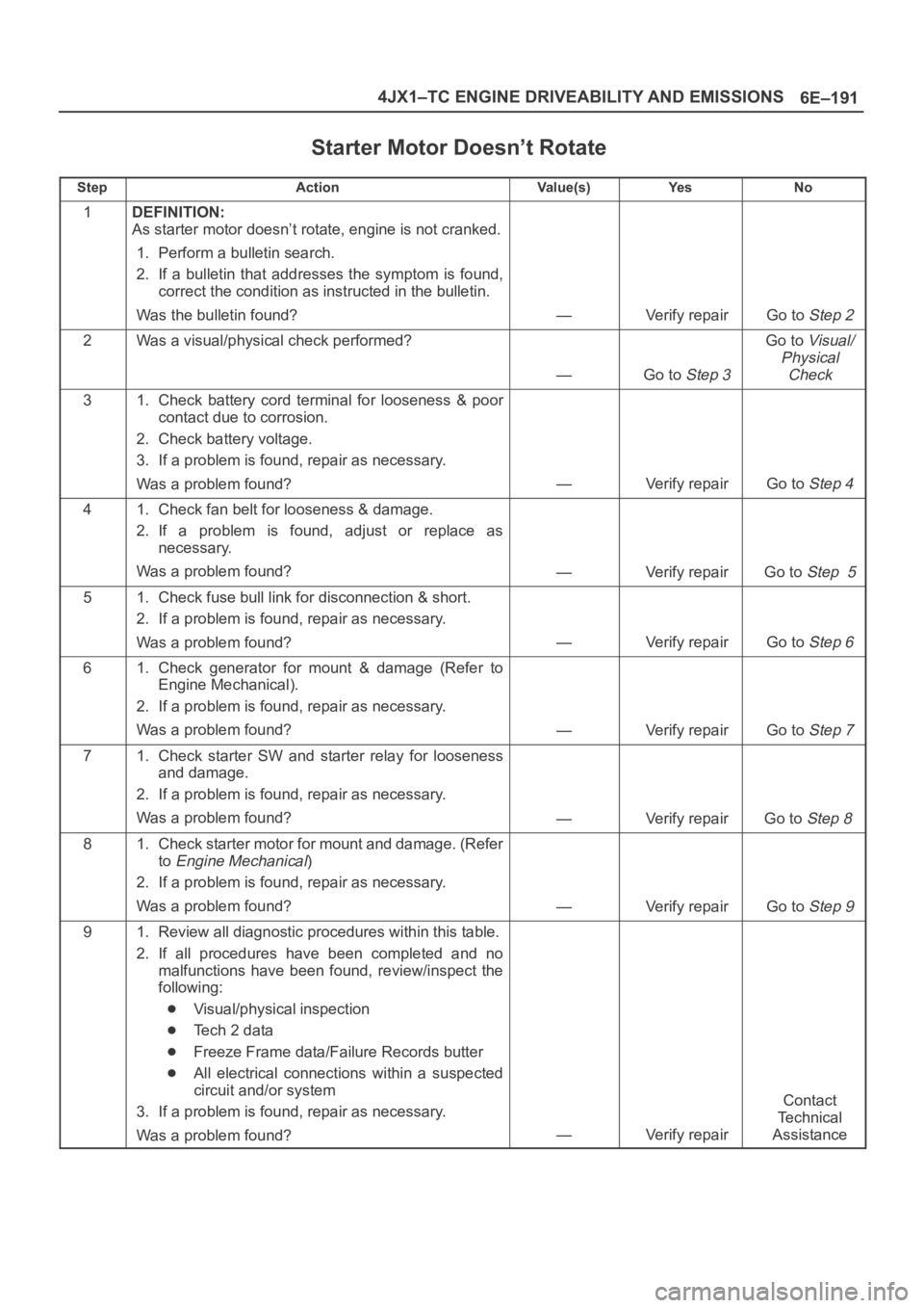
Starter Motor Doesn’t Rotate
StepActionVa l u e ( s )Ye sNo
1DEFINITION:
As starter motor doesn’t rotate, engine is not cranked.
1. Perform a bulletin search.
2. If a bulletin that addresses the symptom is found,
correct the condition as instructed in the bulletin.
Was the bulletin found?
—Verify repairGo to Step 2
2Was a visual/physical check performed?
—Go to Step 3
Go to Visual/
Physical
Check
31. Check battery cord terminal for looseness & poor
contact due to corrosion.
2. Check battery voltage.
3. If a problem is found, repair as necessary.
Was a problem found?
—Verify repairGo to Step 4
41. Check fan belt for looseness & damage.
2. If a problem is found, adjust or replace as
necessary.
Was a problem found?
—Verify repairGo to Step 5
51. Check fuse bull link for disconnection & short.
2. If a problem is found, repair as necessary.
Was a problem found?
—Verify repairGo to Step 6
61. Check generator for mount & damage (Refer to
Engine Mechanical).
2. If a problem is found, repair as necessary.
Was a problem found?
—Verify repairGo to Step 7
71. Check starter SW and starter relay for looseness
and damage.
2. If a problem is found, repair as necessary.
Was a problem found?
—Verify repairGo to Step 8
81. Check starter motor for mount and damage. (Refer
to
Engine Mechanical)
2. If a problem is found, repair as necessary.
Was a problem found?
—Verify repairGo to Step 9
91. Review all diagnostic procedures within this table.
2. If all procedures have been completed and no
malfunctions have been found, review/inspect the
following:
Visual/physical inspection
Te c h 2 d a t a
Freeze Frame data/Failure Records butter
All electrical connections within a suspected
circuit and/or system
3. If a problem is found, repair as necessary.
Was a problem found?
—Verify repair
Contact
Te c h n i c a l
Assistance
Page 2102 of 6000
6E–209 4JX1–TC ENGINE DRIVEABILITY AND EMISSIONS
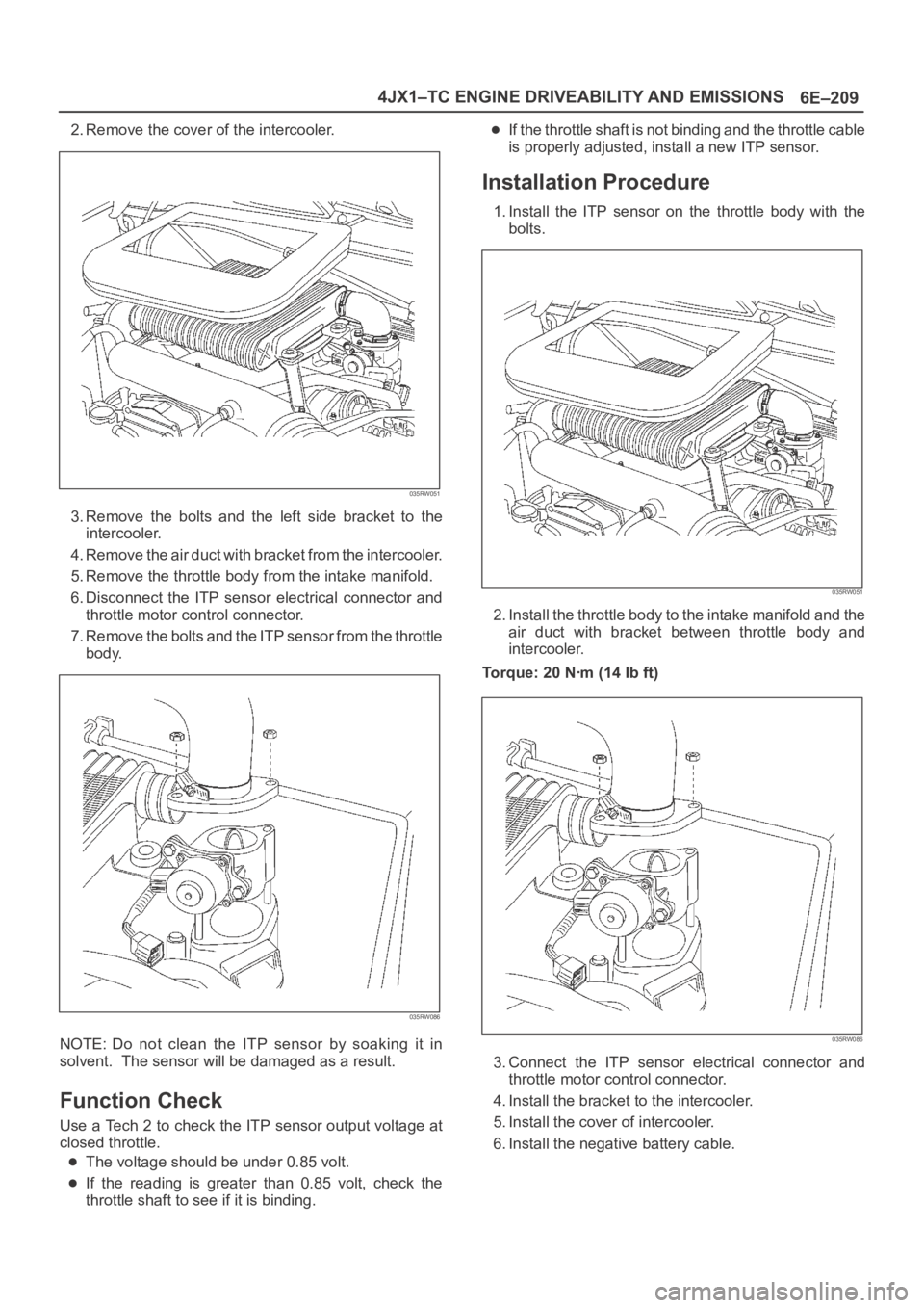
2. Remove the cover of the intercooler.
035RW051
3. Remove the bolts and the left side bracket to the
intercooler.
4 . R e m o v e t h e a i r d u c t w i t h b r a c k e t f r o m t h e i n t e r c o o l e r.
5. Remove the throttle body from the intake manifold.
6. Disconnect the ITP sensor electrical connector and
throttle motor control connector.
7. Remove the bolts and the ITP sensor from the throttle
body.
035RW086
NOTE: Do not clean the ITP sensor by soaking it in
solvent. The sensor will be damaged as a result.
Function Check
Use a Tech 2 to check the ITP sensor output voltage at
closed throttle.
The voltage should be under 0.85 volt.
If the reading is greater than 0.85 volt, check the
throttle shaft to see if it is binding.
If the throttle shaft is not binding and the throttle cable
is properly adjusted, install a new ITP sensor.
Installation Procedure
1. Install the ITP sensor on the throttle body with the
bolts.
035RW051
2. Install the throttle body to the intake manifold and the
air duct with bracket between throttle body and
intercooler.
Torque: 20 Nꞏm (14 Ib ft)
035RW086
3. Connect the ITP sensor electrical connector and
throttle motor control connector.
4. Install the bracket to the intercooler.
5. Install the cover of intercooler.
6. Install the negative battery cable.
Page 2110 of 6000
6E–217 4JX1–TC ENGINE DRIVEABILITY AND EMISSIONS
Throttle Body (TB)
Removal Procedure
1. Disconnect the negative battery cable.
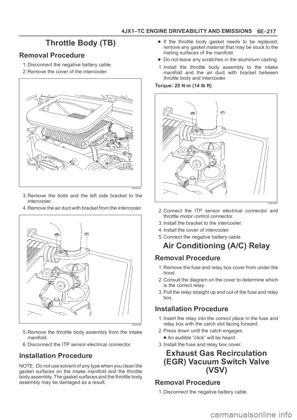
2. Remove the cover of the intercooler.
035RW051
3. Remove the bolts and the left side bracket to the
intercooler.
4 . R e m o v e t h e a i r d u c t w i t h b r a c k e t f r o m t h e i n t e r c o o l e r.
035RW086
5. Remove the throttle body assembly from the intake
manifold.
6. Disconnect the ITP sensor electrical connector.
Installation Procedure
NOTE: Do not use solvent of any type when you clean the
gasket surfaces on the intake manifold and the throttle
body assembly. The gasket surfaces and the throttle body
assembly may be damaged as a result.
If the throttle body gasket needs to be replaced,
remove any gasket material that may be stuck to the
mating surfaces of the manifold.
Do not leave any scratches in the aluminum casting.
1. Install the throttle body assembly to the intake
manifold and the air duct with bracket between
throttle body and intercooler.
Torque: 20 Nꞏm (14 Ib ft)
035RW086
2. Connect the ITP sensor electrical connector and
throttle motor control connector.
3. Install the bracket to the intercooler.
4. Install the cover of intercooler.
5. Connect the negative battery cable.
Air Conditioning (A/C) Relay
Removal Procedure
1. Remove the fuse and relay box cover from under the
hood.
2. Consult the diagram on the cover to determine which
is the correct relay.
3. Pull the relay straight up and out of the fuse and relay
box.
Installation Procedure
1. Insert the relay into the correct place in the fuse and
relay box with the catch slot facing forward.
2. Press down until the catch engages.
An audible “click” will be heard.
3. Install the fuse and relay box cover.
Exhaust Gas Recirculation
(EGR) Vacuum Switch Valve
(VSV)
Removal Procedure
1. Disconnect the negative battery cable.
Page 2151 of 6000

6J – 10 INDUCTION
REMOVAL
1. Remove intercooler assembly.
Refer to “Intercooler” in this manual.
2. Remove harness connector from motor and ITP
sensor.
3. Loosen the two fixing nuts and remove the throttle
valve assembly.
Legend
(1) Motor
(2) Intake Throttle Valve
(3) ITP sensor
INSPECTION AND REPAIR
1. Check for catching somwhere on the throttle valve.
2. If some problem is discovered during inspection on
the throttle valve, the throttle valve must replace.
INSTALLATION
1. Put gasket on the intake manifold and install throttle
valve.
2. Tighten nuts to the specified torque.
Torque: 20 Nꞏm (2.0 kgꞏm / 14.5 lb ft)
3. Reconnect harness connector to motor and
ITPsensor.
4. Install intercooler assembly.
1 2 3
025RW032
I N TA K E T H R O T T L E VA LV E
Page 2174 of 6000
7A–20
AUTOMATIC TRANSMISSION (4L30–E)
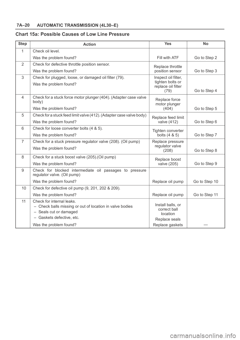
Chart 15a: Possible Causes of Low Line Pressure
StepActionYe sNo
1Check oil level.
Was the problem found?
Fill with ATFGo to Step 2
2Check for defective throttle position sensor.
Was the problem found?Replace throttle
position sensor
Go to Step 3
3Check for plugged, loose, or damaged oil filter (79).
Was the problem found?Inspect oil filter,
tighten bolts or
replace oil filter
(79)
Go to Step 4
4Check for a stuck force motor plunger (404). (Adapter case valve
body)
Was the problem found?Replace force
motor plunger
(404)
Go to Step 5
5Check for a stuck feed limit valve (412). (Adapter case valve body)
Was the problem found?Replace feed limit
valve (412)
Go to Step 6
6Check for loose converter bolts (4 & 5).
Was the problem found?Tighten converter
bolts (4 & 5)
Go to Step 7
7Check for a stuck pressure regulator valve (208). (Oil pump)
Was the problem found?Replace pressure
regulator valve
(208)
Go to Step 8
8Check for a stuck boost valve (205).(Oil pump)
Was the problem found?Replace boost
valve (205)
Go to Step 9
9Check for blocked intermediate oil passages to pressure
regulator valve. (Oil pump)
Was the problem found?
Replace oil pumpGo to Step 10
10Check for defective oil pump (9, 201, 202 & 209).
Was the problem found?
Replace oil pumpGo to Step 11
11Check for internal leaks.
– Check balls missing or out of location in valve bodies
– Seals cut or damaged
– Gaskets defective, etc.
Was the problem found?Install balls, or
correct ball
location
Replace seals
Replace gaskets
—
Page 2175 of 6000
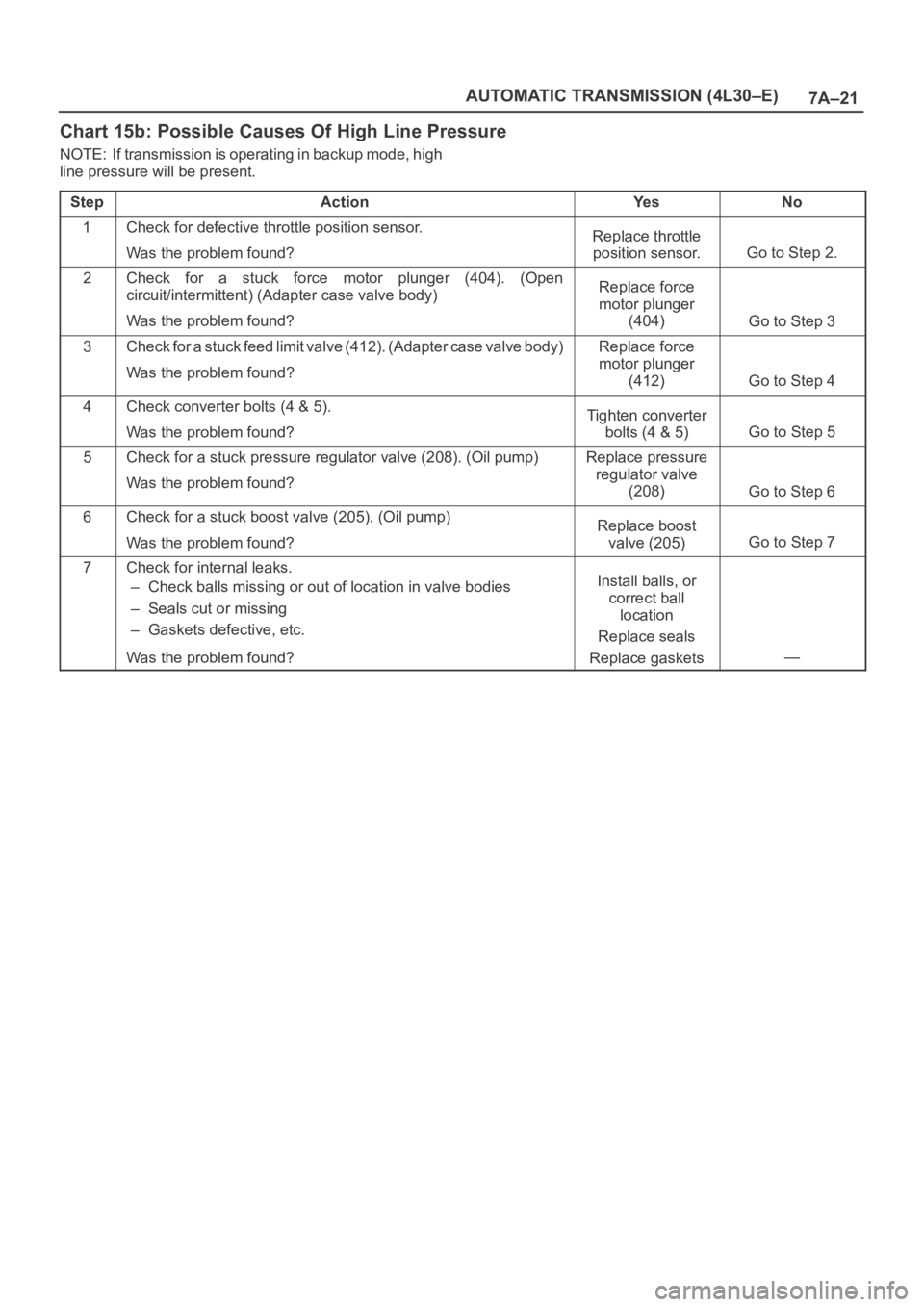
7A–21 AUTOMATIC TRANSMISSION (4L30–E)
Chart 15b: Possible Causes Of High Line Pressure
NOTE: If transmission is operating in backup mode, high
line pressure will be present.
Step
ActionYe sNo
1Check for defective throttle position sensor.
Was the problem found?Replace throttle
position sensor.
Go to Step 2.
2Check for a stuck force motor plunger (404). (Open
circuit/intermittent) (Adapter case valve body)
Was the problem found?Replace force
motor plunger
(404)
Go to Step 3
3Check for a stuck feed limit valve (412). (Adapter case valve body)
Was the problem found?Replace force
motor plunger
(412)
Go to Step 4
4Check converter bolts (4 & 5).
Was the problem found?Tighten converter
bolts (4 & 5)
Go to Step 5
5Check for a stuck pressure regulator valve (208). (Oil pump)
Was the problem found?Replace pressure
regulator valve
(208)
Go to Step 6
6Check for a stuck boost valve (205). (Oil pump)
Was the problem found?Replace boost
valve (205)
Go to Step 7
7Check for internal leaks.
– Check balls missing or out of location in valve bodies
– Seals cut or missing
– Gaskets defective, etc.
Was the problem found?Install balls, or
correct ball
location
Replace seals
Replace gaskets
—
Page 2178 of 6000
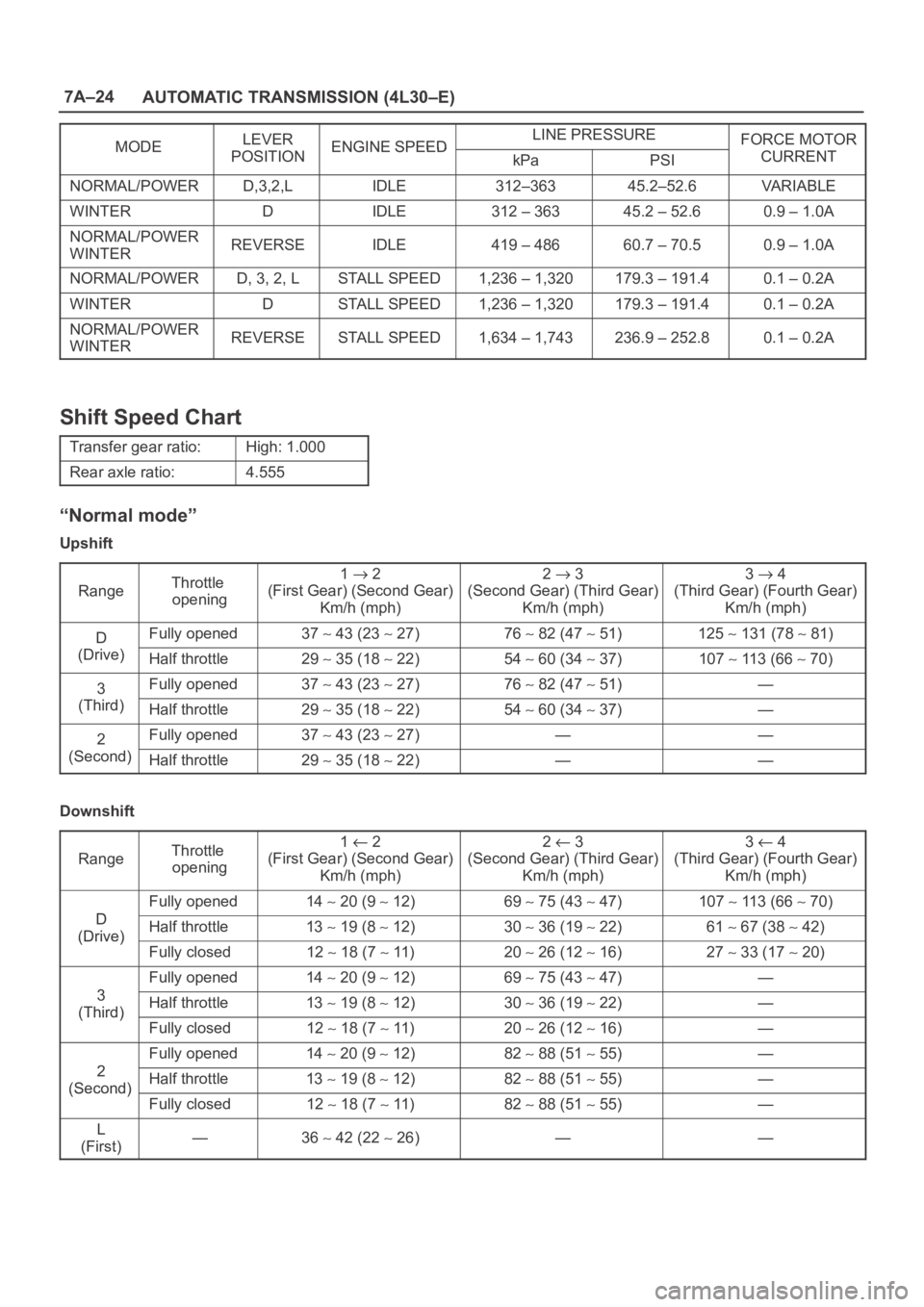
7A–24
AUTOMATIC TRANSMISSION (4L30–E)
MODELEVERENGINE SPEEDLINE PRESSUREFORCE MOTORMODEPOSITIONENGINE SPEEDkPaPSICURRENT
NORMAL/POWERD,3,2,LIDLE312–36345.2–52.6VA R I A B L E
WINTERDIDLE312 – 36345.2 – 52.60.9 – 1.0A
NORMAL/POWER
WINTERREVERSEIDLE419 – 48660.7 – 70.50.9 – 1.0A
NORMAL/POWERD, 3, 2, LSTALL SPEED1,236 – 1,320179.3 – 191.40.1 – 0.2A
WINTERDSTALL SPEED1,236 – 1,320179.3 – 191.40.1 – 0.2A
NORMAL/POWER
WINTERREVERSESTALL SPEED1,634 – 1,743236.9 – 252.80.1 – 0.2A
Shift Speed Chart
Transfer gear ratio:High: 1.000
Rear axle ratio:4.555
“Normal mode”
Upshift
Range
Throttle
opening1 2
(First Gear) (Second Gear)
Km/h (mph)2 3
(Second Gear) (Third Gear)
Km/h (mph)3 4
(Third Gear) (Fourth Gear)
Km/h (mph)
DFully opened37 43 (23 27)76 82 (47 51)125 131 (78 81)
(Drive)Half throttle29 35 (18 22)54 60 (34 37)107 113 (66 70)
3Fully opened37 43 (23 27)76 82 (47 51)—
(Third)Half throttle29 35 (18 22)54 60 (34 37)—
2Fully opened37 43 (23 27)——
(Second)Half throttle29 35 (18 22)——
Downshift
Range
Throttle
opening1 2
(First Gear) (Second Gear)
Km/h (mph)2 3
(Second Gear) (Third Gear)
Km/h (mph)3 4
(Third Gear) (Fourth Gear)
Km/h (mph)
D
Fully opened14 20 (9 12)69 75 (43 47)107 113 (66 70)
D
(Drive)Half throttle13 19 (8 12)30 36 (19 22)61 67 (38 42)(Drive)
Fully closed12 18 (7 11)20 26 (12 16)27 33 (17 20)
3
Fully opened14 20 (9 12)69 75 (43 47)—
3
(Third)Half throttle13 19 (8 12)30 36 (19 22)—(Third)
Fully closed12 18 (7 11)20 26 (12 16)—
2
Fully opened14 20 (9 12)82 88 (51 55)—
2
(Second)Half throttle13 19 (8 12)82 88 (51 55)—(Second)
Fully closed12 18 (7 11)82 88 (51 55)—
L
(First)—36 42 (22 26)——
Page 2191 of 6000
7A–37 AUTOMATIC TRANSMISSION (4L30–E)
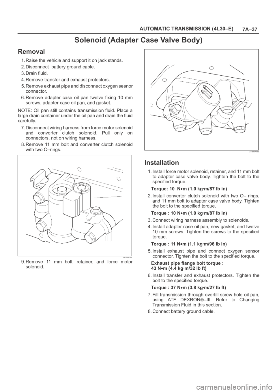
Solenoid (Adapter Case Valve Body)
Removal
1. Raise the vehicle and support it on jack stands.
2. Disconnect battery ground cable.
3. Drain fluid.
4. Remove transfer and exhaust protectors.
5. Remove exhaust pipe and disconnect oxygen sesnor
connector.
6. Remove adapter case oil pan twelve fixing 10 mm
screws, adapter case oil pan, and gasket.
NOTE: Oil pan still contains transmission fluid. Place a
large drain container under the oil pan and drain the fluid
carefully.
7. Disconnect wiring harness from force motor solenoid
and converter clutch solenoid. Pull only on
connectors, not on wiring harness.
8. Remove 11 mm bolt and converter clutch solenoid
with two O–rings.
210RW011
9. Remove 11 mm bolt, retainer, and force motor
solenoid.
210RW009
Installation
1. Install force motor solenoid, retainer, and 11 mm bolt
to adapter case valve body. Tighten the bolt to the
specified torque.
To r q u e : 1 0 N
m (1.0 kgꞏm/87 lb in)
2. Install converter clutch solenoid with two O– rings,
and 11 mm bolt to adapter case valve body. Tighten
the bolt to the specified torque.
Torque : 10 N
m (1.0 kgꞏm/87 lb in)
3. Connect wiring harness assembly to solenoids.
4. Install adapter case oil pan, new gasket, and twelve
10 mm screws. Tighten the screws to the specified
torque.
Torque : 11 N
m (1.1 kgꞏm/96 lb in)
5. Install exhaust pipe and connect oxygen sensor
connector. Tighten the bolt to the specified torque.
Exhaust pipe flange bolt torque :
43 N
m(4.4kgꞏm/32lbft)
6. Install transfer and exhaust protectors. Tighten the
bolt to the specified torque.
Torque : 37 N
m(3.8kgꞏm/27lbft)
7. Fill transmission through overfill screw hole oil pan,
using ATF DEXRON
–III. Refer to Changing
Transmission Fluid in this section.
8. Connect battery ground cable.