1998 OPEL FRONTERA lock
[x] Cancel search: lockPage 2524 of 6000
CLUTCH7C–15
Installation
To install, follow the removal steps in the reverse order,
noting the following points:
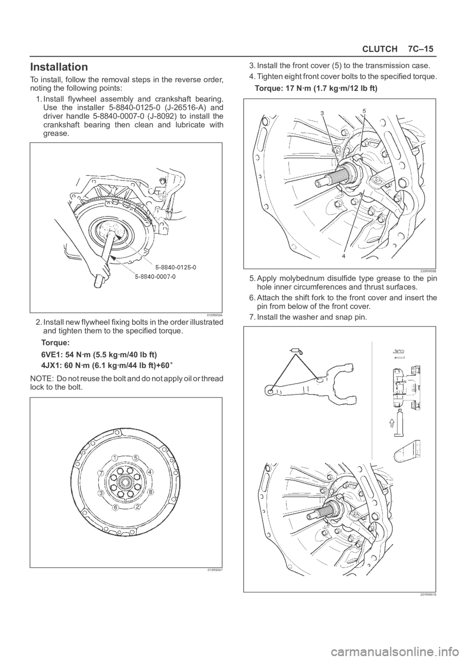
1. Install flywheel assembly and crankshaft bearing.
Use the installer 5-8840-0125-0 (J-26516-A) and
driver handle 5-8840-0007-0 (J-8092) to install the
crankshaft bearing then clean and lubricate with
grease.
015RW054
2. Install new flywheel fixing bolts in the order illustrated
and tighten them to the specified torque.
Torque:
6VE1: 54 Nꞏm (5.5 kgꞏm/40 lb ft)
4JX1: 60 Nꞏm (6.1 kgꞏm/44 lb ft)+60
NOTE: Do not reuse the bolt and do not apply oil or thread
lock to the bolt.
015RS047
3. Install the front cover (5) to the transmission case.
4. Tighten eight front cover bolts to the specified torque.
Torque: 17 Nꞏm (1.7 kgꞏm/12 lb ft)
220RW088
5. Apply molybednum disulfide type grease to the pin
hole inner circumferences and thrust surfaces.
6. Attach the shift fork to the front cover and insert the
pin from below of the front cover.
7. Install the washer and snap pin.
201RW019
Page 2528 of 6000
CLUTCH7C–19
Installation
1. Install damper cylinder assembly (except V6 LHD).
2. Install master cylinder assembly.
3. Install slave cylinder assembly and heat protector.
4. Install oil line pipe.
5. Install pedal assembly.
6. Install pin and jaw joint pin.
Adjustment
Clutch Pedal Adjustment
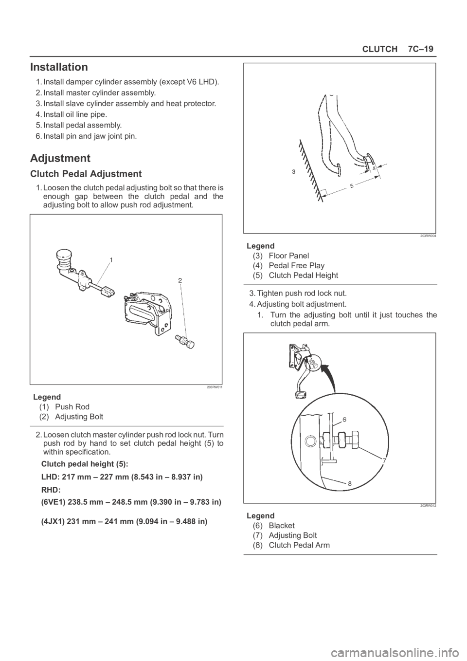
1. Loosen the clutch pedal adjusting bolt so that there is
enough gap between the clutch pedal and the
adjusting bolt to allow push rod adjustment.
203RW011
Legend
(1) Push Rod
(2) Adjusting Bolt
2. Loosen clutch master cylinder push rod lock nut. Turn
push rod by hand to set clutch pedal height (5) to
within specification.
Clutch pedal height (5):
LHD: 217 mm – 227 mm (8.543 in – 8.937 in)
RHD:
(6VE1) 238.5 mm – 248.5 mm (9.390 in – 9.783 in)
(4JX1) 231 mm – 241 mm (9.094 in – 9.488 in)
203RW004
Legend
(3) Floor Panel
(4) Pedal Free Play
(5) Clutch Pedal Height
3. Tighten push rod lock nut.
4. Adjusting bolt adjustment.
1. Turn the adjusting bolt until it just touches the
clutch pedal arm.
203RW012
Legend
(6) Blacket
(7) Adjusting Bolt
(8) Clutch Pedal Arm
Page 2529 of 6000
7C–20CLUTCH
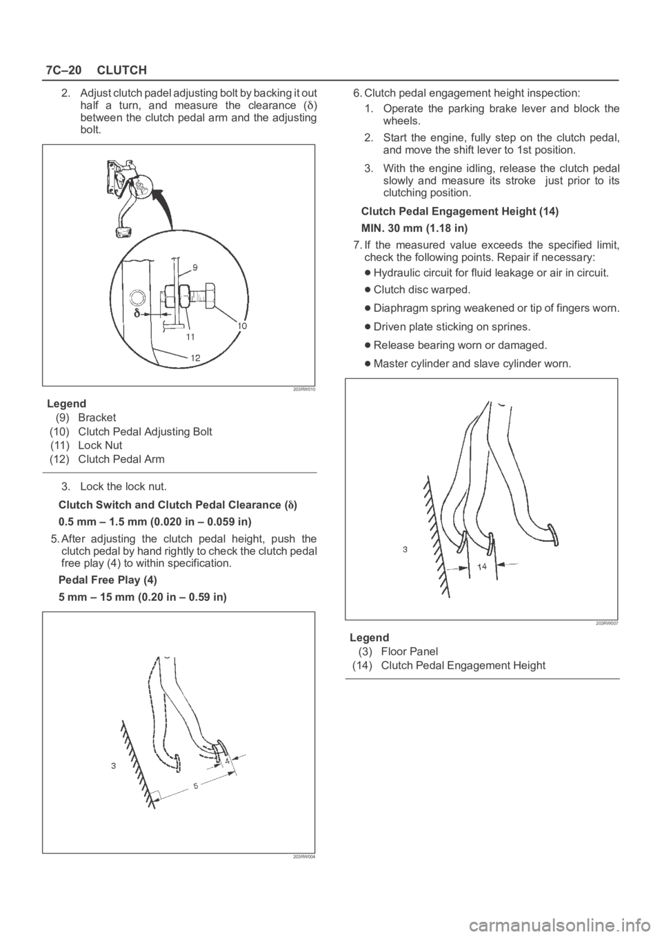
2. Adjust clutch padel adjusting bolt by backing it out
half a turn, and measure the clearance (
)
between the clutch pedal arm and the adjusting
bolt.
203RW010
Legend
(9) Bracket
(10) Clutch Pedal Adjusting Bolt
(11) Lock Nut
(12) Clutch Pedal Arm
3. Lock the lock nut.
Clutch Switch and Clutch Pedal Clearance (
)
0.5 mm – 1.5 mm (0.020 in – 0.059 in)
5. After adjusting the clutch pedal height, push the
clutch pedal by hand rightly to check the clutch pedal
free play (4) to within specification.
Pedal Free Play (4)
5 mm – 15 mm (0.20 in – 0.59 in)
203RW004
6. Clutch pedal engagement height inspection:
1. Operate the parking brake lever and block the
wheels.
2. Start the engine, fully step on the clutch pedal,
and move the shift lever to 1st position.
3. With the engine idling, release the clutch pedal
slowly and measure its stroke just prior to its
clutching position.
Clutch Pedal Engagement Height (14)
MIN. 30 mm (1.18 in)
7. If the measured value exceeds the specified limit,
check the following points. Repair if necessary:
Hydraulic circuit for fluid leakage or air in circuit.
Clutch disc warped.
Diaphragm spring weakened or tip of fingers worn.
Driven plate sticking on sprines.
Release bearing worn or damaged.
Master cylinder and slave cylinder worn.
203RW007
Legend
(3) Floor Panel
(14) Clutch Pedal Engagement Height
Page 2540 of 6000
LIGHTING SYSTEM8A–1
BODY AND ACCESSORIES
CONTENTS
Lighting System 8A. . . . . . . . . . . . . . . . . . . . . . . . .
Wiper/Washer System 8B. . . . . . . . . . . . . . . . . . .
Entertainment 8C. . . . . . . . . . . . . . . . . . . . . . . . . . .
Wiring System 8D. . . . . . . . . . . . . . . . . . . . . . . . . .
Meter and Gauge 8E. . . . . . . . . . . . . . . . . . . . . . . Body Structure 8F. . . . . . . . . . . . . . . . . . . . . . . . . .
Seats 8G. . . . . . . . . . . . . . . . . . . . . . . . . . . . . . . . . .
Security and Locks 8H. . . . . . . . . . . . . . . . . . . . . .
Sun Roof/Convertible Top 8I. . . . . . . . . . . . . . . .
Exterior/Interior Trim 8J. . . . . . . . . . . . . . . . . . . . .
LIGHTING SYSTEM
CONTENTS
Service Precaution 8A–2. . . . . . . . . . . . . . . . . . . . . .
Headlight Bulb 8A–3. . . . . . . . . . . . . . . . . . . . . . . . . .
Removal 8A–3. . . . . . . . . . . . . . . . . . . . . . . . . . . . .
Installation 8A–3. . . . . . . . . . . . . . . . . . . . . . . . . . . .
Headlight 8A–4. . . . . . . . . . . . . . . . . . . . . . . . . . . . . . .
Headlight and Associated Parts 8A–4. . . . . . . . .
Removal 8A–4. . . . . . . . . . . . . . . . . . . . . . . . . . . . .
Installation 8A–4. . . . . . . . . . . . . . . . . . . . . . . . . . . .
Headlight Adjustment 8A–4. . . . . . . . . . . . . . . . . .
Fog Light Bulb 8A–5. . . . . . . . . . . . . . . . . . . . . . . . . .
Removal 8A–5. . . . . . . . . . . . . . . . . . . . . . . . . . . . .
Installation 8A–5. . . . . . . . . . . . . . . . . . . . . . . . . . . .
Fog Light Assembly 8A–6. . . . . . . . . . . . . . . . . . . . .
Removal 8A–6. . . . . . . . . . . . . . . . . . . . . . . . . . . . .
Installation 8A–6. . . . . . . . . . . . . . . . . . . . . . . . . . . .
Fog Light Adjustment 8A–6. . . . . . . . . . . . . . . . . .
Clarence Light Bulb 8A–6. . . . . . . . . . . . . . . . . . . . . .
Removal 8A–6. . . . . . . . . . . . . . . . . . . . . . . . . . . . .
Installation 8A–6. . . . . . . . . . . . . . . . . . . . . . . . . . . .
Rear Fog Light Bulb (RHD) 8A–7. . . . . . . . . . . . . . .
Removal 8A–7. . . . . . . . . . . . . . . . . . . . . . . . . . . . .
Installation 8A–7. . . . . . . . . . . . . . . . . . . . . . . . . . . .
Taillight Bulb (Body) 8A–7. . . . . . . . . . . . . . . . . . . . .
Removal 8A–7. . . . . . . . . . . . . . . . . . . . . . . . . . . . .
Installation 8A–7. . . . . . . . . . . . . . . . . . . . . . . . . . . .
Taillight Bulb (Bumper) 8A–8. . . . . . . . . . . . . . . . . . .
Removal 8A–8. . . . . . . . . . . . . . . . . . . . . . . . . . . . .
Installation 8A–8. . . . . . . . . . . . . . . . . . . . . . . . . . . .
License Plate Light Bulb (Body) 8A–8. . . . . . . . . . .
Removal 8A–8. . . . . . . . . . . . . . . . . . . . . . . . . . . . .
Installation 8A–8. . . . . . . . . . . . . . . . . . . . . . . . . . . .
License Plate Light Bulb (Bumper) 8A–9. . . . . . . . .
Removal 8A–9. . . . . . . . . . . . . . . . . . . . . . . . . . . . .
Installation 8A–9. . . . . . . . . . . . . . . . . . . . . . . . . . . .
Stoplight Bulb 8A–9. . . . . . . . . . . . . . . . . . . . . . . . . . .
Removal and Installation 8A–9. . . . . . . . . . . . . . . High Mount Stoplight 8A–10. . . . . . . . . . . . . . . . . . . .
Removal 8A–10. . . . . . . . . . . . . . . . . . . . . . . . . . . . .
Installation 8A–10. . . . . . . . . . . . . . . . . . . . . . . . . . . .
Front Turn Signal Light Bulb 8A–10. . . . . . . . . . . . . .
Removal 8A–10. . . . . . . . . . . . . . . . . . . . . . . . . . . . .
Installation 8A–10. . . . . . . . . . . . . . . . . . . . . . . . . . . .
Side Turn Signal Light Bulb 8A–11. . . . . . . . . . . . . . .
Removal 8A–11. . . . . . . . . . . . . . . . . . . . . . . . . . . . .
Installation 8A–11. . . . . . . . . . . . . . . . . . . . . . . . . . . .
Rear Turn Signal Light Bulb 8A–11. . . . . . . . . . . . . .
Removal 8A–11. . . . . . . . . . . . . . . . . . . . . . . . . . . . .
Installation 8A–11. . . . . . . . . . . . . . . . . . . . . . . . . . .
Backup Light Bulb 8A–12. . . . . . . . . . . . . . . . . . . . . . .
Removal 8A–12. . . . . . . . . . . . . . . . . . . . . . . . . . . . .
Installation 8A–12
. . . . . . . . . . . . . . . . . . . . . . . . . . .
Dome Light Bulb 8A–12. . . . . . . . . . . . . . . . . . . . . . . .
Removal 8A–12. . . . . . . . . . . . . . . . . . . . . . . . . . . . .
Installation 8A–12. . . . . . . . . . . . . . . . . . . . . . . . . . . .
Luggage Room Light Bulb 8A–13. . . . . . . . . . . . . . . .
Removal 8A–13. . . . . . . . . . . . . . . . . . . . . . . . . . . . .
Installation 8A–13. . . . . . . . . . . . . . . . . . . . . . . . . . . .
Courtesy Light Bulb 8A–13. . . . . . . . . . . . . . . . . . . . . .
Removal 8A–13. . . . . . . . . . . . . . . . . . . . . . . . . . . . .
Installation 8A–13. . . . . . . . . . . . . . . . . . . . . . . . . . . .
Map Light Switch/Bulb 8A–14. . . . . . . . . . . . . . . . . . .
Removal 8A–14. . . . . . . . . . . . . . . . . . . . . . . . . . . . .
Installation 8A–14. . . . . . . . . . . . . . . . . . . . . . . . . . . .
Cigarette Lighter Illumination Bulb 8A–14. . . . . . . . .
Removal 8A–14. . . . . . . . . . . . . . . . . . . . . . . . . . . . .
Installation 8A–14. . . . . . . . . . . . . . . . . . . . . . . . . . .
Ashtray Illumination Bulb 8A–15. . . . . . . . . . . . . . . . .
Removal 8A–15. . . . . . . . . . . . . . . . . . . . . . . . . . . . .
Installation 8A–15. . . . . . . . . . . . . . . . . . . . . . . . . . . .
Glove Box Illumination Bulb 8A–15. . . . . . . . . . . . . . .
Removal 8A–15. . . . . . . . . . . . . . . . . . . . . . . . . . . . .
Installation 8A–15. . . . . . . . . . . . . . . . . . . . . . . . . . . .
Page 2541 of 6000
8A–2LIGHTING SYSTEM
Vanity Mirror Illumination Bulb 8A–16. . . . . . . . . . . . .
Removal 8A–16. . . . . . . . . . . . . . . . . . . . . . . . . . . . .
Installation 8A–16. . . . . . . . . . . . . . . . . . . . . . . . . . .
Starter Switch 8A–17. . . . . . . . . . . . . . . . . . . . . . . . . . .
Removal 8A–17. . . . . . . . . . . . . . . . . . . . . . . . . . . . .
Installation 8A–17. . . . . . . . . . . . . . . . . . . . . . . . . . . .
Lighting Switch (Combination Switch) 8A–18. . . . . .
Removal 8A–18. . . . . . . . . . . . . . . . . . . . . . . . . . . . .
Installation 8A–18. . . . . . . . . . . . . . . . . . . . . . . . . . . .
Fog Light Switch 8A–19. . . . . . . . . . . . . . . . . . . . . . . .
Removal 8A–19. . . . . . . . . . . . . . . . . . . . . . . . . . . . .
Installation 8A–19. . . . . . . . . . . . . . . . . . . . . . . . . . . .
Stoplight Switch (W/O Cruise Control) 8A–20. . . . . .
Removal 8A–20. . . . . . . . . . . . . . . . . . . . . . . . . . . . .
Installation 8A–20. . . . . . . . . . . . . . . . . . . . . . . . . . . .
Brake Switch (W/Cruise Control) 8A–21. . . . . . . . . .
Removal 8A–21. . . . . . . . . . . . . . . . . . . . . . . . . . . . .
Installation 8A–21. . . . . . . . . . . . . . . . . . . . . . . . . . . .
Turn Signal Switch (Combination Switch) 8A–21. . .
Removal and Installation 8A–21. . . . . . . . . . . . . . .
Hazard Warning Switch 8A–22. . . . . . . . . . . . . . . . . .
Removal 8A–22. . . . . . . . . . . . . . . . . . . . . . . . . . . . . Installation 8A–22. . . . . . . . . . . . . . . . . . . . . . . . . . . .
Tailgate Switch 8A–23. . . . . . . . . . . . . . . . . . . . . . . . . .
Removal 8A–23. . . . . . . . . . . . . . . . . . . . . . . . . . . . .
Installation 8A–23. . . . . . . . . . . . . . . . . . . . . . . . . . . .
Door Switch 8A–23. . . . . . . . . . . . . . . . . . . . . . . . . . . .
Removal 8A–23. . . . . . . . . . . . . . . . . . . . . . . . . . . . .
Installation 8A–23. . . . . . . . . . . . . . . . . . . . . . . . . . . .
Rear Defogger Switch 8A–24. . . . . . . . . . . . . . . . . . .
Removal 8A–24. . . . . . . . . . . . . . . . . . . . . . . . . . . . .
Installation 8A–24. . . . . . . . . . . . . . . . . . . . . . . . . . .
Seat Heater Switch 8A–25. . . . . . . . . . . . . . . . . . . . . .
Removal 8A–25. . . . . . . . . . . . . . . . . . . . . . . . . . . . .
Installation 8A–25. . . . . . . . . . . . . . . . . . . . . . . . . . . .
Key Remind Switch (Starter Switch) 8A–25. . . . . . .
Removal and Installation 8A–25. . . . . . . . . . . . . . .
Illumination Controller 8A–26. . . . . . . . . . . . . . . . . . . .
Removal 8A–26. . . . . . . . . . . . . . . . . . . . . . . . . . . . .
Installation 8A–26. . . . . . . . . . . . . . . . . . . . . . . . . . .
Power/Winter Switch 8A–27. . . . . . . . . . . . . . . . . . . . .
Removal 8A–27. . . . . . . . . . . . . . . . . . . . . . . . . . . . .
Installation 8A–27. . . . . . . . . . . . . . . . . . . . . . . . . . .
Main Data and Specifications 8A–28. . . . . . . . . . . . .
Service Precaution
WARNING: IF SO EQUIPPED WITH A
SUPPLEMENTAL RESTRAINT SYSTEM (SRS),
REFER TO THE SRS COMPONENT AND WIRING
LOCATION VIEW IN ORDER TO DETERMINE
WHETHER YOU ARE PERFORMING SERVICE ON OR
NEAR THE SRS COMPONENTS OR THE SRS
WIRING. WHEN YOU ARE PERFORMING SERVICE
ON OR NEAR THE SRS COMPONENTS OR THE SRS
WIRING, REFER TO THE SRS SERVICE
INFORMATION. FAILURE TO FOLLOW WARNINGS
COULD RESULT IN POSSIBLE AIR BAG
DEPLOYMENT, PERSONAL INJURY, OR
OTHERWISE UNNEEDED SRS SYSTEM REPAIRS.
CAUTION: Always use the correct fastener in the
proper location. When you replace a fastener, use
ONLY the exact part number for that application.
ISUZU will call out those fasteners that require a
replacement after removal. ISUZU will also call out
the fasteners that require thread lockers or thread
sealant. UNLESS OTHERWISE SPECIFIED, do not
use supplemental coatings (Paints, greases, or other
corrosion inhibitors) on threaded fasteners or
fastener joint interfaces. Generally, such coatings
adversely affect the fastener torque and the joint
clamping force, and may damage the fastener. When
you install fasteners, use the correct tightening
sequence and specifications. Following these
instructions can help you avoid damage to parts and
systems.
Page 2542 of 6000
LIGHTING SYSTEM8A–3
Headlight Bulb
Removal
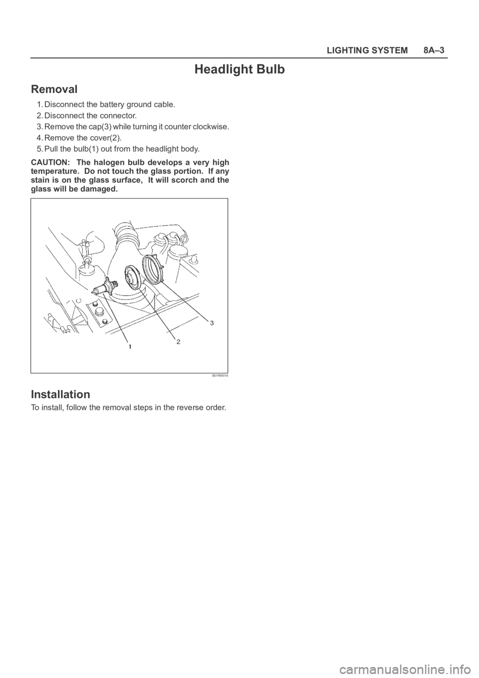
1. Disconnect the battery ground cable.
2. Disconnect the connector.
3. Remove the cap(3) while turning it counter clockwise.
4. Remove the cover(2).
5. Pull the bulb(1) out from the headlight body.
CAUTION: The halogen bulb develops a very high
temperature. Do not touch the glass portion. If any
stain is on the glass surface, It will scorch and the
glass will be damaged.
801RW014
Installation
To install, follow the removal steps in the reverse order.
Page 2545 of 6000
8A–6LIGHTING SYSTEM
Fog Light Assembly
Removal
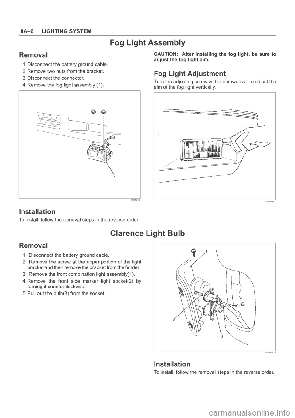
1. Disconnect the battery ground cable.
2. Remove two nuts from the bracket.
3. Disconnect the connector.
4. Remove the fog light assembly (1).
825RW104
Installation
To install, follow the removal steps in the reverse order.CAUTION: After installing the fog light, be sure to
adjust the fog light aim.
Fog Light Adjustment
Turn the adjusting screw with a screwdriver to adjust the
aim of the fog light vertically.
801RW007
Clarence Light Bulb
Removal
1. Disconnect the battery ground cable.
2. Remove the screw at the upper portion of the light
bracket and then remove the bracket from the fender.
3. Remove the front combination light assembly(1).
4. Remove the front side marker light socket(2) by
turning it counterclockwise.
5. Pull out the bulb(3) from the socket.
801RW015
Installation
To install, follow the removal steps in the reverse order.
Page 2546 of 6000
LIGHTING SYSTEM8A–7
Rear Fog Light Bulb (RHD)
Removal
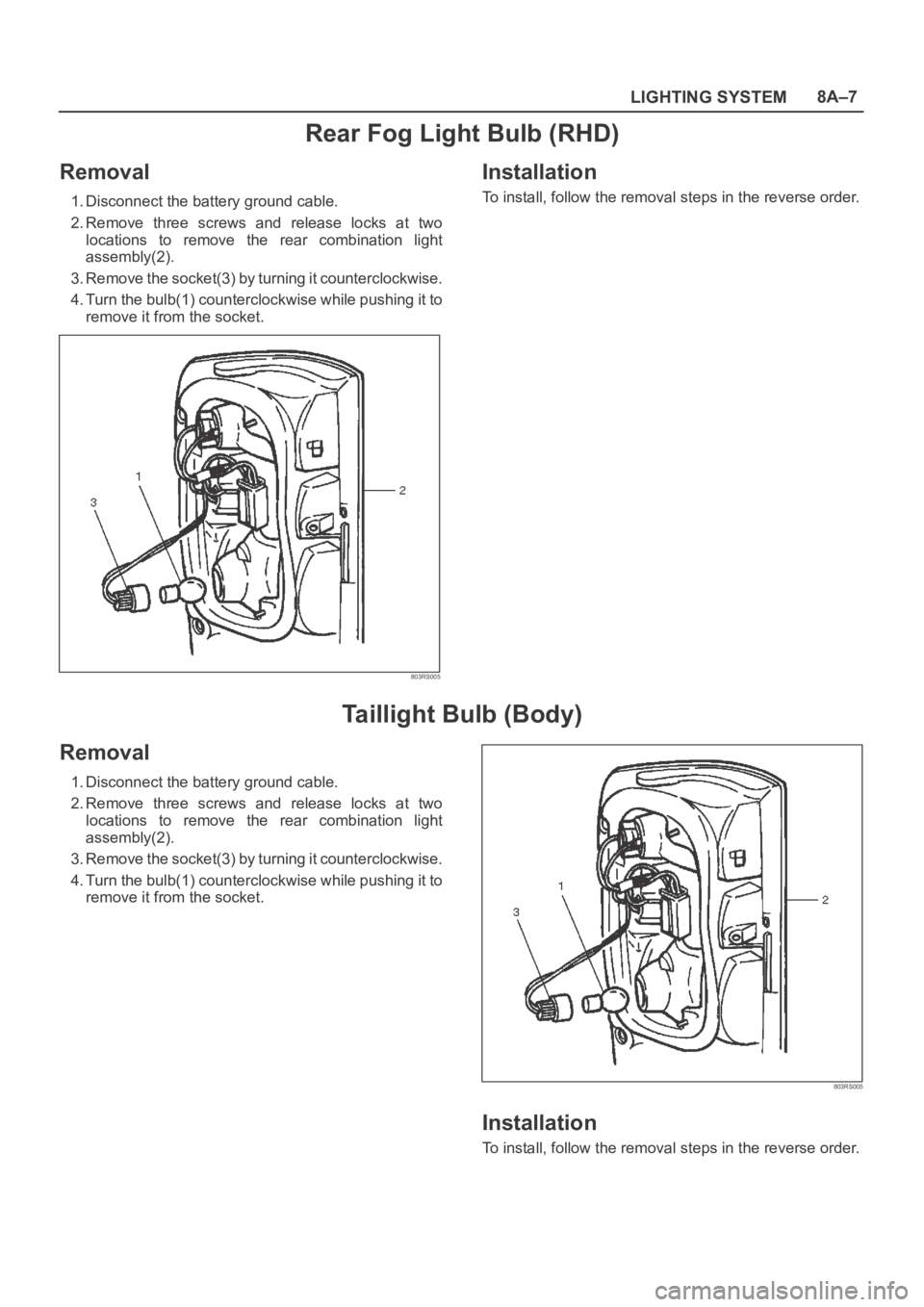
1. Disconnect the battery ground cable.
2. Remove three screws and release locks at two
locations to remove the rear combination light
assembly(2).
3. Remove the socket(3) by turning it counterclockwise.
4. Turn the bulb(1) counterclockwise while pushing it to
remove it from the socket.
803RS005
Installation
To install, follow the removal steps in the reverse order.
Taillight Bulb (Body)
Removal
1. Disconnect the battery ground cable.
2. Remove three screws and release locks at two
locations to remove the rear combination light
assembly(2).
3. Remove the socket(3) by turning it counterclockwise.
4. Turn the bulb(1) counterclockwise while pushing it to
remove it from the socket.
803RS005
Installation
To install, follow the removal steps in the reverse order.