Page 5969 of 6000
7A–188 AUTOMATIC TRANSMISSION (AW30-40LE)
248RY00014
248RY00019
248RY00020
247RY00012
7. Snap ring
Install the snap ring.
Check pack clearance of second brake
Using a thickness gauge, measure the clearance between
the snap ring and flange as shown in the figure.
If the values are nonstandard, check for an improper
installation.
8. Drum
While turning the sun gear input drum clockwise, install it
into the one-way clutch.
NOTE:
Confirm the thrust washers are installed correctly.
9. Front planetary gear and bearing
Install the front planetary gear to the sun gear.
NOTE:
Confirm the bearing and race is installed correctly.mm (in.)
Clearance0.62–1.98
(0.0244–0.0780)
Page 5970 of 6000
AUTOMATIC TRANSMISSION (AW30-40LE) 7A–189
247RY00013
248RY00017
247RY00014
248RY00010
With wooden blocks under the output shaft, stand the
transmission on the output shaft.
10. Snap ring
Using snap ring pliers, install the snap ring.
11. Race
Coat the bearing race with petroleum jelly and install it onto
the front planetary gear.
12. Second coast brake band
Insert the second coast brake band to the case. Bearing race diameter (Reference) mm (in.)
Bearing race Diameter
Inside 34.3 (1.350)
Outside 47.8 (1.882)
Page 5983 of 6000
7A–202 AUTOMATIC TRANSMISSION (AW30-40LE)
240RY00017
244RY00017
249RY00011
249RY00012
4. Valve body
Align the groove of the manual valve to the pin of the lever.
Install the twenty bolts.
Each bolt length (mm) is indicated in the figure.
5. Solenoid wiring
Coat a new O–ring with ATF, and install it to the solenoid
wiring.
Insert the solenoid wiring to the case and install the stopper
plate.
Connect the connectors to the solenoid S1(1), S2(2), lock-
up solenoid (3), and pressure control solenoid (4).Nꞏm (kgꞏm/lbꞏin)
Torque 10 (1.0/87)
Page 5987 of 6000

7A–206 AUTOMATIC TRANSMISSION (AW30-40LE)
249RW003
249RY00008
240RY00005
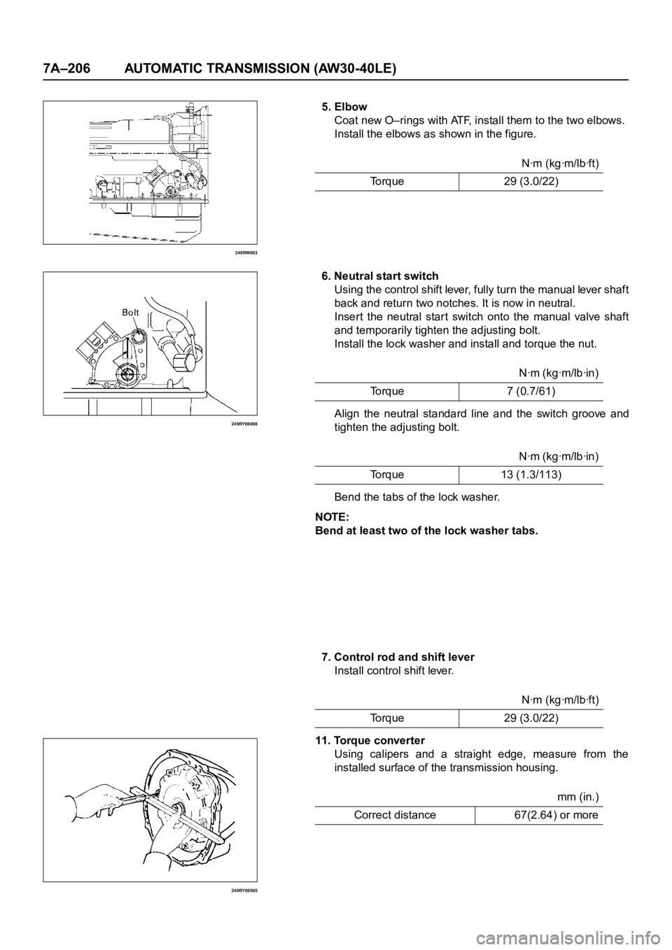
5. Elbow
Coat new O–rings with ATF, install them to the two elbows.
Install the elbows as shown in the figure.
6. Neutral start switch
Using the control shift lever, fully turn the manual lever shaft
back and return two notches. It is now in neutral.
Insert the neutral star t switch onto the manual valve shaft
and temporarily tighten the adjusting bolt.
Install the lock washer and install and torque the nut.
Align the neutral standard line and the switch groove and
tighten the adjusting bolt.
Bend the tabs of the lock washer.
NOTE:
Bend at least two of the lock washer tabs.
7. Control rod and shift lever
Install control shift lever.
11. Torque converter
Using calipers and a straight edge, measure from the
installed surface of the transmission housing.Nꞏm (kgꞏm/lbꞏft)
Torque 29 (3.0/22)
Nꞏm (kgꞏm/lbꞏin)
To r q u e 7 ( 0 . 7 / 6 1 )
Nꞏm (kgꞏm/lbꞏin)
Torque 13 (1.3/113)
Nꞏm (kgꞏm/lbꞏft)
Torque 29 (3.0/22)
mm (in.)
Correct distance 67(2.64) or more
Page 5995 of 6000

7A1–2
TRANSMISSION CONTROL SYSTEM (4L30–E)
Service Precaution
WARNING: IF SO EQUIPPED WITH A
SUPPLEMENTAL RESTRAINT SYSTEM (SRS),
REFER TO THE SRS COMPONENT AND WIRING
LOCATION VIEW IN ORDER TO DETERMINE
WHETHER YOU ARE PERFORMING SERVICE ON OR
NEAR THE SRS COMPONENTS OR THE SRS
WIRING. WHEN YOU ARE PERFORMING SERVICE
ON OR NEAR THE SRS COMPONENTS OR THE SRS
WIRING, REFER TO THE SRS SERVICE
INFORMATION. FAILURE TO FOLLOW WARNINGS
COULD RESULT IN POSSIBLE AIR BAG
DEPLOYMENT, PERSONAL INJURY, OR
OTHERWISE UNNEEDED SRS SYSTEM REPAIRS.
CAUTION: Always use the correct fastener in the
proper location. When you replace a fastener, use
ONLY the exact part number for that application.
ISUZU will call out those fasteners that require a
replacement after removal. ISUZU will also call out
the fasteners that require thread lockers or thread
sealant. UNLESS OTHERWISE SPECIFIED, do not
use supplemental coatings (Paints, greases, or other
corrosion inhibitors) on threaded fasteners or
fastener joint interfaces. Generally, such coatings
adversely affect the fastener torque and the joint
clamping force, and may damage the fastener. When
you install fasteners, use the correct tightening
sequence and specifications. Following these
instructions can help you avoid damage to parts and
systems.
General Description
The 4L30–E is a 4–speed fully automatic transmission. It
uses a microcomputer as a control unit to judge running
conditions including throttle opening rate and vehicle
speed, then it sets the shifting point in the optimum timing
so that best driving performance can be achieved.
In addition, the built–in shift mode select function can
select three shift modes according to the driver’s
preference:
Normal mode –Normal shift pattern.
Winter mode –Starts in 3rd gear to reduce slippage on
ice or snow.
Power mode has a delayed upshift for when more
powerful acceleration is required.
Also, the built–in fail safe function (“backup mode”)
assures driving performance even if the vehicle speed
sensor, throttle signal or any solenoid fails.
Further, the self–diagnostic function conducts diagnosis
in a short time when the control system fails, thus
improving serviceability.
The major features of 4L30–E are as follows:
A compact structure consisting of 2 sets of planetary
gears and flat torque converter.
Electronic control selects the optimum shift mode
according to the driving conditions.
Electronic control maintains the optimum hydraulic
pressure for clutch, band brake as well as
transmission so that shift feeling is improved.
Two sets of planetary gears reduce friction of power
train.
Also, a lockup mechanism in the torque converter
reduces fuel consumption.
Wide gear ratio and high torque rate of torque
converter provide excellent starting performance.