Page 5831 of 6000

7A–50 AUTOMATIC TRANSMISSION (AW30-40LE)
DTC P1121 (FLASHING CODE 23) ANALOG THROTTLE SIGNAL FAILURE (VREF, VGND)
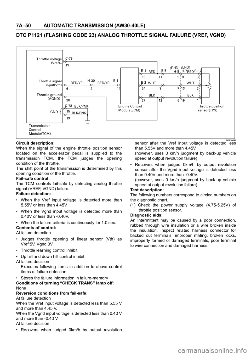
D07RY00023Circuit description:
When the signal of the engine throttle position sensor
located on the accelerator pedal is supplied to the
transmission TCM, the TCM judges the opening
condition of the throttle.
The shift point of the transmission is determined by this
opening condition of the throttle.
Fail-safe control:
The TCM controls fail-safe by detecting analog throttle
signal (VREF, VGND) failure.
Failure detection:
• When the Vref input voltage is detected more than
5.55V or less than 4.45V.
• When the Vgnd input voltage is detected more than
0.40V or less than -0.40V.
• When the failure criteria is continuously for 1.0 sec.
Contents of control:
At failure detection
• Judges throttle opening of linear sensor (Vth) as
Vref:5V, Vgnd:0V
• Throttle learning control inhibit
• Up hill and down hill control inhibit
At failure decision
Executes following items in addition to above control
items at failure detection.
• Stores the failure information in failure-memory
Conditions of turning “CHECK TRANS” lamp off:
None
Reversion conditions from fail-safe:
At failure detection
When the Vref input voltage is detected less than 5.55 V
and more than 4.45 V.
When the Vgnd input voltage is detected less than 0.40 V
and more than -0.40 V.
At failure decision
• Recovers when judged 0km/h by output revolutionsensor after the Vref input voltage is detected less
than 5.55V and more than 4.45V.
(however, uses 0 km/h judgment by back-up vehicle
speed at output revolution failure)
• Recovers when judged 0km/h by output revolution
sensor after the Vgnd input voltage is detected less
than 0.40V and more than -0.40V.
(however, uses 0 km/h judgment by back-up vehicle
speed at output revolution failure)
Test description:
The following numbers correspond to circled numbers on
the diagnostic char t.
(1) Check the power supply voltage (4.75-5.25V) of
throttle position sensor.
Diagnostic aids:
An intermittent may be caused by a poor connection,
rubbed through wire insulation or a wire broken inside
the insulation. Inspect related harness connector for
backed out terminals, improper mating, broken locks,
improperly formed or damaged terminals, poor terminal
to wire connection and damaged harness.
Page 5847 of 6000

7A–66 AUTOMATIC TRANSMISSION (AW30-40LE)
255RT004
F07RY00005
F07RY00006
ROAD TEST
NOTE:
Perform the test at normal operation fluid temperature (50
– 80
C or 122 – 176F).
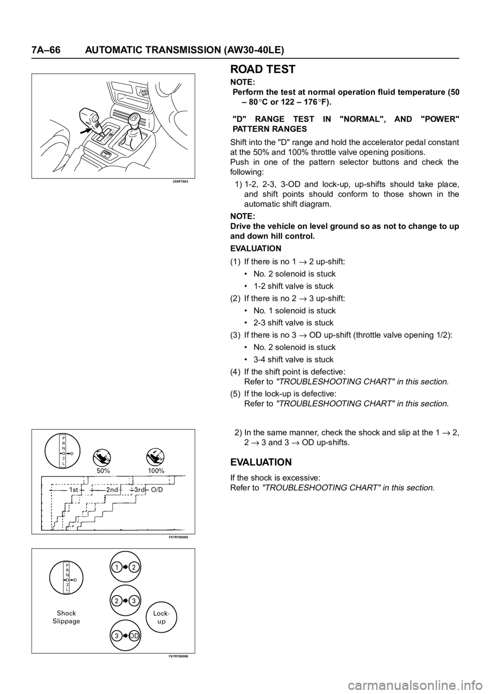
"D" RANGE TEST IN "NORMAL", AND "POWER"
PATTERN RANGES
Shift into the "D" range and hold the accelerator pedal constant
at the 50% and 100% throttle valve opening positions.
Push in one of the pattern selector buttons and check the
fol lowing:
1) 1-2, 2-3, 3-OD and lock-up, up-shifts should take place,
and shift points should conform to those shown in the
automatic shift diagram.
NOTE:
Drive the vehicle on level ground so as not to change to up
and down hill control.
EVALUATION
(1) If there is no 1
2 up-shift:
• No. 2 solenoid is stuck
• 1-2 shift valve is stuck
(2) If there is no 2
3 up-shift:
• No. 1 solenoid is stuck
• 2-3 shift valve is stuck
(3) If there is no 3
OD up-shift (throttle valve opening 1/2):
• No. 2 solenoid is stuck
• 3-4 shift valve is stuck
(4) If the shift point is defective:
Refer to
"TROUBLESHOOTING CHART" in this section.
(5) If the lock-up is defective:
Refer to
"TROUBLESHOOTING CHART" in this section.
2) In the same manner, check the shock and slip at the 1 2,
2
3 and 3 OD up-shifts.
EVALUATION
If the shock is excessive:
Refer to
"TROUBLESHOOTING CHART" in this section.
Page 5848 of 6000

AUTOMATIC TRANSMISSION (AW30-40LE) 7A–67
F07RY00007
F07RY00008
F07RY00009
F07RY00010
3) Run at "D" range lock-up or OD gear and check for
abnormal noise and vibration.
NOTE:
The check for the cause of abnormal noise and vibration
must be made with extreme care as it could also be due to
loss of balance in the propeller shaft, differential, the
torque converter, etc. or insufficient bending, rigidity, etc.
in the power train.
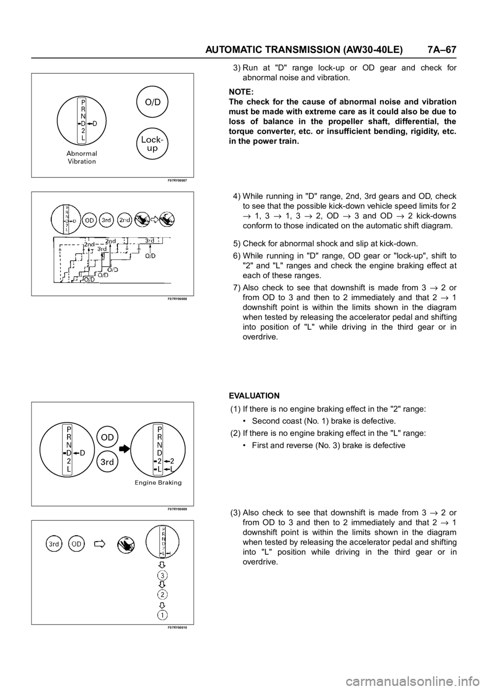
4) While running in "D" range, 2nd, 3rd gears and OD, check
to see that the possible kick-down vehicle speed limits for 2
1, 3 1, 3 2, OD 3 and OD 2 kick-downs
conform to those indicated on the automatic shift diagram.
5) Check for abnormal shock and slip at kick-down.
6) While running in "D" range, OD gear or "lock-up", shift to
"2" and "L" ranges and check the engine braking effect at
each of these ranges.
7) Also check to see that downshift is made from 3
2 or
from OD to 3 and then to 2 immediately and that 2
1
downshift point is within the limits shown in the diagram
when tested by releasing the accelerator pedal and shifting
into position of "L" while driving in the third gear or in
overdrive.
EVALUATION
(1) If there is no engine braking effect in the "2" range:
• Second coast (No. 1) brake is defective.
(2) If there is no engine braking effect in the "L" range:
• First and reverse (No. 3) brake is defective
(3) Also check to see that downshift is made from 3
2 or
from OD to 3 and then to 2 immediately and that 2
1
downshift point is within the limits shown in the diagram
when tested by releasing the accelerator pedal and shifting
into "L" position while driving in the third gear or in
overdrive.
Page 5849 of 6000

7A–68 AUTOMATIC TRANSMISSION (AW30-40LE)
F07RY00011
F07RY00012
F07RY00020
F07RY00014
F07RY00015
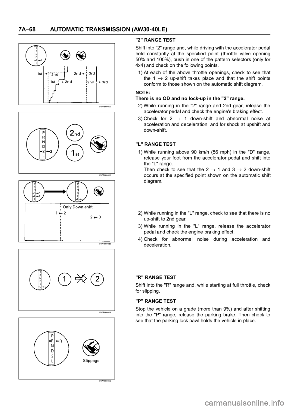
"2" RANGE TEST
Shift into "2" range and, while driving with the accelerator pedal
held constantly at the specified point (throttle valve opening
50% and 100%), push in one of the pattern selectors (only for
4x4) and check on the following points.
1) At each of the above throttle openings, check to see that
the 1
2 up-shift takes place and that the shift points
conform to those shown on the automatic shift diagram.
NOTE:
There is no OD and no lock-up in the "2" range.
2) While running in the "2" range and 2nd gear, release the
accelerator pedal and check the engine's braking effect.
3) Check for 2
1 down-shift and abnormal noise at
acceleration and deceleration, and for shock at upshift and
down-shift.
"L" RANGE TEST
1) While running above 90 km/h (56 mph) in the "D" range,
release your foot from the accelerator pedal and shift into
the "L" range.
Then check to see that the 2
1 and 3 2 down-shift
occurs at the specified point shown on the automatic shift
diagram.
2) While running in the "L" range, check to see that there is no
up-shift to 2nd gear.
3) While running in the "L" range, release the accelerator
pedal and check the engine braking effect.
4) Check for abnormal noise during acceleration and
deceleration.
"R" RANGE TEST
Shift into the "R" range and, while starting at full throttle, check
for slipping.
"P" RANGE TEST
Stop the vehicle on a grade (more than 9%) and after shifting
into the "P" range, release the parking brake. Then check to
see that the parking lock pawl holds the vehicle in place.
Page 5850 of 6000

AUTOMATIC TRANSMISSION (AW30-40LE) 7A–69
SHIFT POINT CHART AND LOCK-UP POINT CHART
SHIFT POINT CHART
(H2, H4)
(REAR AXLE RATIO: 4.300)
(RADIUS OF TIRE: 0.363m)
“NORMAL” mode
Up shift km/h
Down shift km/h
“POWER” mode
Up shiftkm/h
Down shift km/h Range Throttle Opening 1
2 2 3 3 4
DFully opened 39 - 45 78 - 84 128 - 134
Half throttle 22 - 28 48 - 54 89 - 95
2Fully opened 39 - 45 89 - 95 —
Half throttle 22 - 28 89 - 95 —
Range Throttle Opening 1
2 2 3 3 4
DFully opened 30 - 36 65 - 71 115 - 121
Half throttle 9 - 15 27 - 33 64 - 70
Fully closed 9 - 15 22 - 28 37 - 43
2Fully opened 30 - 36 85 - 91 —
Half throttle 9 - 15 85 - 91 —
Fully closed 9 - 15 85 - 91 —
LFully opened 43 - 49 85 - 91 —
Half throttle 43 - 49 85 - 91 —
Fully closed 43 - 49 85 - 91 —
Range Throttle Opening 1
22 3 3 4
DFully opened 39 - 45 78 - 84 128 - 134
Half throttle 29 - 35 58 - 64 89 - 95
2Fully opened 39 - 45 89 - 95 —
Half throttle 22 - 28 89 - 95 —
Range Throttle Opening 1
22 33 4
DFully opened 30 - 36 65 - 71 115 - 121
Half throttle 11 - 17 45 - 51 74 - 80
Fully closed 9 - 15 22 - 28 37 - 43
2Fully opened 30 - 36 85 - 91 —
Half throttle 9 - 15 85 - 91 —
Fully closed 9 - 15 85 - 91 —
LFully opened 43 - 49 85 - 91 —
Half throttle 43 - 49 85 - 91 —
Fully closed 43 - 49 85 - 91 —
Page 5851 of 6000
7A–70 AUTOMATIC TRANSMISSION (AW30-40LE)
LOCK-UP POINT CHART
(H2, H4)
(REAR AXLE RATIO: 4.300)
(RADIUS OF TIRE: 0.363m)
km/h
Range A/T ModeThrottle Opening : 20%
Lock-up ON Lock-up OFF
3rd 4th 3rd 4th
DNORMAL 47 - 53 62 - 68 45 - 51 55 - 61
POWER 47 - 53 66 - 72 45 - 51 55 - 61
Page 5854 of 6000
AUTOMATIC TRANSMISSION (AW30-40LE) 7A–73
Check circuitTe r m i n a l
Measuring condition Voltage (V)
+-
Winter lamp C79-12C78-15
or -19Winter lamp ON Less than 1
Winter lamp OFF 8
16
Solenoid S1 C78-4C78-15
or -19OFF (3rd or O/D) Less than 1
ON (1st or 2nd) 8
16
Solenoid S2 C78-3C78-15
or -19OFF (1st or O/D) Less than 1
ON (2nd or 3rd) 8
16
Lock up solenoid SL C78-12C78-15
or -19OFF (Lock up OFF) Less than 1
ON (Lock up ON) 8
16
Pressure control solenoid C78-11 C78-8At throttle pressure changing Less than
1
8-16
Oil temperature sensor C79-18 C79-27ATF temperature 20
C4.70
ATF temperature 80
C3.65
Tech 2 diagnosis terminal
(J1850)C78-6C78-15
or -19On diagnosis communication 0-1.5
6.25-8.0
Throttle position sensor
(ground)C79-19C78-15
or -19Key switch ON
-0.1
0.1
Page 5857 of 6000
7A–76 AUTOMATIC TRANSMISSION (AW30-40LE)
249RY00010
249RY00008
NEUTRAL START SWITCH INSPECTION
Inspection
With a circuit tester, make a continuity test on the neutral star t
switch with the moving piece set in each position.
Continuity
Removal
Preparation:
Disconnect negative (–) battery cable.
1. Remove rear sound cover.
2. Remove the rear side ATF cooler pipe from the
transmission elbow.
3. Disconnect neutral star t switch connector.
4. Unstake the lock washer, and then remove the shaft nut.
5. Remove the neutral start switch.
Installation
To install, follow the removal steps in the reverse order, noting
the following points;
Adjustment
1) Loosen the neutral star t switch bolt and set the shift
selector to the "N" range.
2) Align the groove and neutral basic line.
3) Hold in position and tighten the bolt.Te r m i n a l
Po s i ti on143526879
P
R
N
D
2
L
Torque Nꞏm (kgꞏcm/lbꞏin)
Nut 7 (70/61)
Bolt 13 (130/113)