Page 5737 of 6000
7A–48
AUTOMATIC TRANSMISSION (4L30–E)
15. Remove servo piston assembly (15), return spring
(16), and servo apply rod (17).
242RW006
16. Rotate transmission to horizontal position, pan side
down.
Remove one 10mm screw, and speed sensor (18)
with “O” ring.
17. Remove seven 8mm extension housing hexagon
socket head screws, extension housing assembly
(19), and gasket.
18. Remove retaining ring (20).
NOTE: Use extra long, needle- nose pliers.19. Remove speed wheel (21).
20. Remove wheel parking lock (with seal ring) (22).
241RS002
21. Rotate transmission to vertical position, converter
housing up.
Loosen the converter housing and oil pump
assembly fixing screws, but do not remove the five
13 mm inner screws if oil pump disassembly is
required.
Remove seven outer screws.
Remove converter housing and oil pump assembly
(23).
22. Remove gasket (24).
Page 5739 of 6000
7A–50
AUTOMATIC TRANSMISSION (4L30–E)
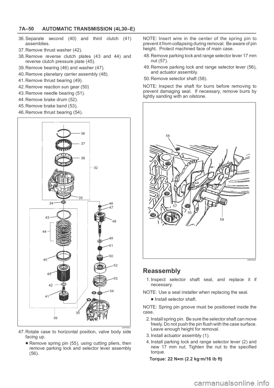
36. Separate second (40) and third clutch (41)
assemblies.
37. Remove thrust washer (42).
38. Remove reverse clutch plates (43 and 44) and
reverse clutch pressure plate (45).
39. Remove bearing (46) and washer (47).
40. Remove planetary carrier assembly (48).
41. Remove thrust bearing (49).
42. Remove reaction sun gear (50)
43. Remove needle bearing (51).
44. Remove brake drum (52).
45. Remove brake band (53).
46. Remove thrust bearing (54).
242RS003
47. Rotate case to horizontal position, valve body side
facing up.
Remove spring pin (55), using cutting pliers, then
remove parking lock and selector lever assembly
(56).NOTE: Insert wire in the center of the spring pin to
prevent it from collapsing during removal. Be aware of pin
height. Protect machined face of main case.
48. Remove parking lock and range selector lever 17 mm
nut (57).
49. Remove parking lock and range selector lever (56),
and actuator assembly.
50. Remove selector shaft (58).
NOTE: Inspect the shaft for burrs before removing to
prevent damaging seal. If necessary, remove burrs by
lightly sanding with an oilstone.
249RS004
Reassembly
1. Inspect selector shaft seal, and replace it if
necessary.
NOTE: Use a seal installer when replacing the seal.
Install selector shaft.
NOTE: Spring pin groove must be positioned inside the
case.
2. Install spring pin. Be sure the selector shaft can move
freely. Do not push the pin flush with the case surface.
Leave enough height for removal.
3. Install actuator assembly (1).
4. Install parking lock and range selector lever (2) and
new 17 mm nut. Tighten the nut to the specified
torque.
To r q u e : 2 2 N
m (2.2 kgꞏm/16 lb ft)
Page 5745 of 6000
7A–56
AUTOMATIC TRANSMISSION (4L30–E)
Ensure free rotation of pump using 5–8840–2273–0
(J–23082–01) oil pump rotation tool.
241RW010
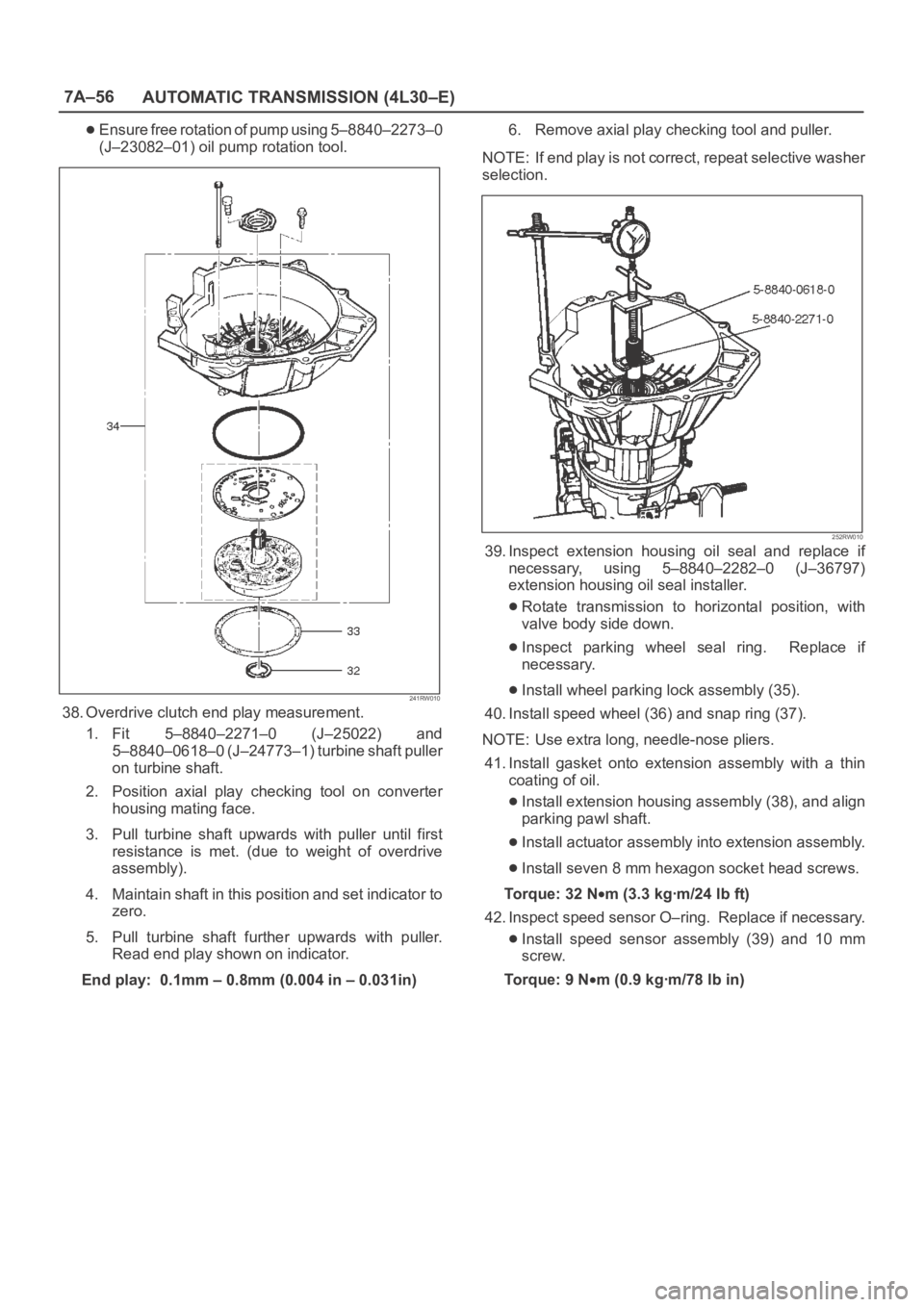
38. Overdrive clutch end play measurement.
1. Fit 5–8840–2271–0 (J–25022) and
5–8840–0618–0 (J–24773–1) turbine shaft puller
on turbine shaft.
2. Position axial play checking tool on converter
housing mating face.
3. Pull turbine shaft upwards with puller until first
resistance is met. (due to weight of overdrive
assembly).
4. Maintain shaft in this position and set indicator to
zero.
5. Pull turbine shaft further upwards with puller.
Read end play shown on indicator.
End play: 0.1mm – 0.8mm (0.004 in – 0.031in)6. Remove axial play checking tool and puller.
NOTE: If end play is not correct, repeat selective washer
selection.
252RW010
39. Inspect extension housing oil seal and replace if
necessary, using 5–8840–2282–0 (J–36797)
extension housing oil seal installer.
Rotate transmission to horizontal position, with
valve body side down.
Inspect parking wheel seal ring. Replace if
necessary.
Install wheel parking lock assembly (35).
40. Install speed wheel (36) and snap ring (37).
NOTE: Use extra long, needle-nose pliers.
41. Install gasket onto extension assembly with a thin
coating of oil.
Install extension housing assembly (38), and align
parking pawl shaft.
Install actuator assembly into extension assembly.
Install seven 8 mm hexagon socket head screws.
To r q u e : 3 2 N
m (3.3 kgꞏm/24 lb ft)
42. Inspect speed sensor O–ring. Replace if necessary.
Install speed sensor assembly (39) and 10 mm
screw.
To r q u e : 9 N
m (0.9 kgꞏm/78 lb in)
Page 5746 of 6000
7A–57 AUTOMATIC TRANSMISSION (4L30–E)
241RW009
241RW019
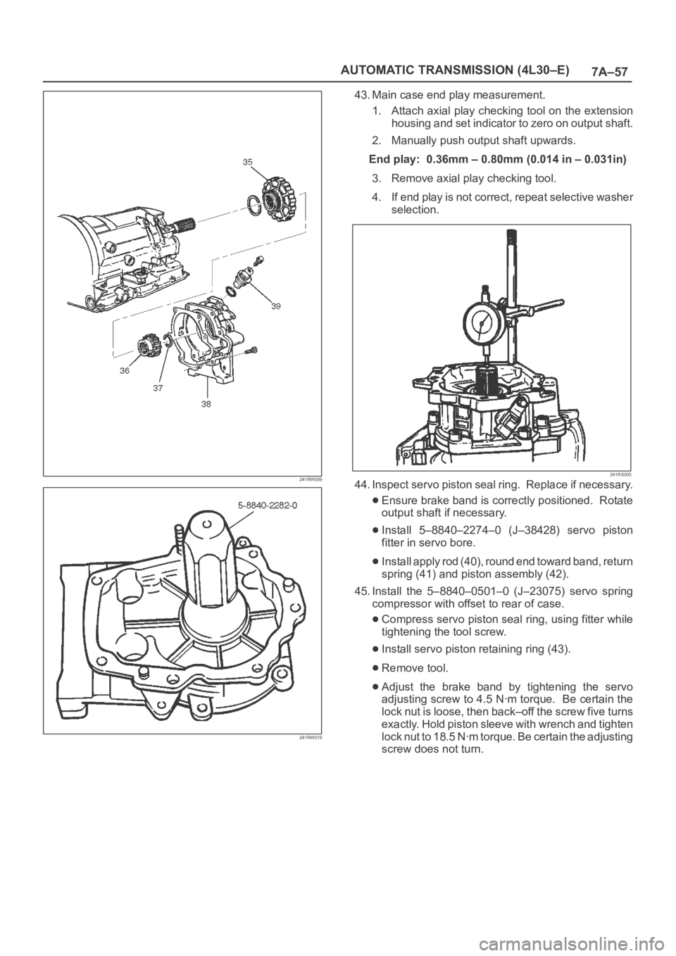
43. Main case end play measurement.
1. Attach axial play checking tool on the extension
housing and set indicator to zero on output shaft.
2. Manually push output shaft upwards.
End play: 0.36mm – 0.80mm (0.014 in – 0.031in)
3. Remove axial play checking tool.
4. If end play is not correct, repeat selective washer
selection.
241RS005
44. Inspect servo piston seal ring. Replace if necessary.
Ensure brake band is correctly positioned. Rotate
output shaft if necessary.
Install 5–8840–2274–0 (J–38428) servo piston
fitter in servo bore.
Install apply rod (40), round end toward band, return
spring (41) and piston assembly (42).
45. Install the 5–8840–0501–0 (J–23075) servo spring
compressor with offset to rear of case.
Compress servo piston seal ring, using fitter while
tightening the tool screw.
Install servo piston retaining ring (43).
Remove tool.
Adjust the brake band by tightening the servo
adjusting screw to 4.5 Nꞏm torque. Be certain the
lock nut is loose, then back–off the screw five turns
exactly. Hold piston sleeve with wrench and tighten
lock nut to 18.5 Nꞏm torque. Be certain the adjusting
screw does not turn.
Page 5758 of 6000
7A–69 AUTOMATIC TRANSMISSION (4L30–E)
Sprag Unit
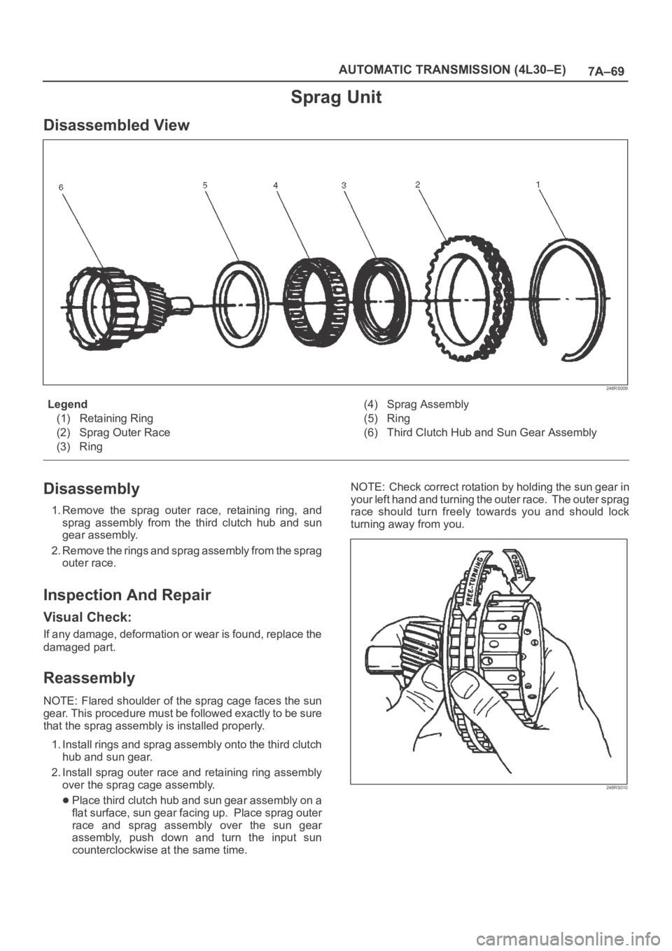
Disassembled View
248RS009
Legend
(1) Retaining Ring
(2) Sprag Outer Race
(3) Ring(4) Sprag Assembly
(5) Ring
(6) Third Clutch Hub and Sun Gear Assembly
Disassembly
1. Remove the sprag outer race, retaining ring, and
sprag assembly from the third clutch hub and sun
gear assembly.
2. Remove the rings and sprag assembly from the sprag
outer race.
Inspection And Repair
Visual Check:
If any damage, deformation or wear is found, replace the
damaged part.
Reassembly
NOTE: Flared shoulder of the sprag cage faces the sun
gear. This procedure must be followed exactly to be sure
that the sprag assembly is installed properly.
1. Install rings and sprag assembly onto the third clutch
hub and sun gear.
2. Install sprag outer race and retaining ring assembly
over the sprag cage assembly.
Place third clutch hub and sun gear assembly on a
flat surface, sun gear facing up. Place sprag outer
race and sprag assembly over the sun gear
assembly, push down and turn the input sun
counterclockwise at the same time. NOTE: Check correct rotation by holding the sun gear in
your left hand and turning the outer race. The outer sprag
race should turn freely towards you and should lock
turning away from you.
248RS010
Page 5763 of 6000
7A–74
AUTOMATIC TRANSMISSION (4L30–E)
Reverse Clutch Piston And Center Support
Disassembled View
242RS006
Legend
(1) Retaining Ring
(2) Spring Seat
(3) Springs
(4) Piston Assembly
(5) Center Support
(6) Gasket(7) Transfer Plate
(8) Gasket
(9) Restrictor
(10) Retainer Plate
(11) Plug
(12) Spring
(13) Overrun Lock Out Valve
Page 5764 of 6000
7A–75 AUTOMATIC TRANSMISSION (4L30–E)
Disassembly
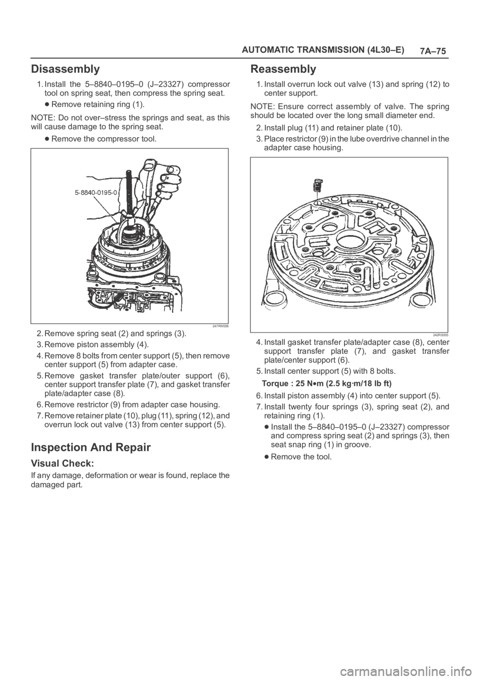
1. Install the 5–8840–0195–0 (J–23327) compressor
tool on spring seat, then compress the spring seat.
Remove retaining ring (1).
NOTE: Do not over–stress the springs and seat, as this
will cause damage to the spring seat.
Remove the compressor tool.
247RW006
2. Remove spring seat (2) and springs (3).
3. Remove piston assembly (4).
4. Remove 8 bolts from center support (5), then remove
center support (5) from adapter case.
5. Remove gasket transfer plate/outer support (6),
center support transfer plate (7), and gasket transfer
plate/adapter case (8).
6. Remove restrictor (9) from adapter case housing.
7. Remove retainer plate (10), plug (11), spring (12), and
overrun lock out valve (13) from center support (5).
Inspection And Repair
Visual Check:
If any damage, deformation or wear is found, replace the
damaged part.
Reassembly
1. Install overrun lock out valve (13) and spring (12) to
center support.
NOTE: Ensure correct assembly of valve. The spring
should be located over the long small diameter end.
2. Install plug (11) and retainer plate (10).
3. Place restrictor (9) in the lube overdrive channel in the
adapter case housing.
242RS005
4. Install gasket transfer plate/adapter case (8), center
support transfer plate (7), and gasket transfer
plate/center support (6).
5. Install center support (5) with 8 bolts.
Torque : 25 N
m (2.5 kgꞏm/18 lb ft)
6. Install piston assembly (4) into center support (5).
7. Install twenty four springs (3), spring seat (2), and
retaining ring (1).
Install the 5–8840–0195–0 (J–23327) compressor
and compress spring seat (2) and springs (3), then
seat snap ring (1) in groove.
Remove the tool.
Page 5768 of 6000
7A–79 AUTOMATIC TRANSMISSION (4L30–E)
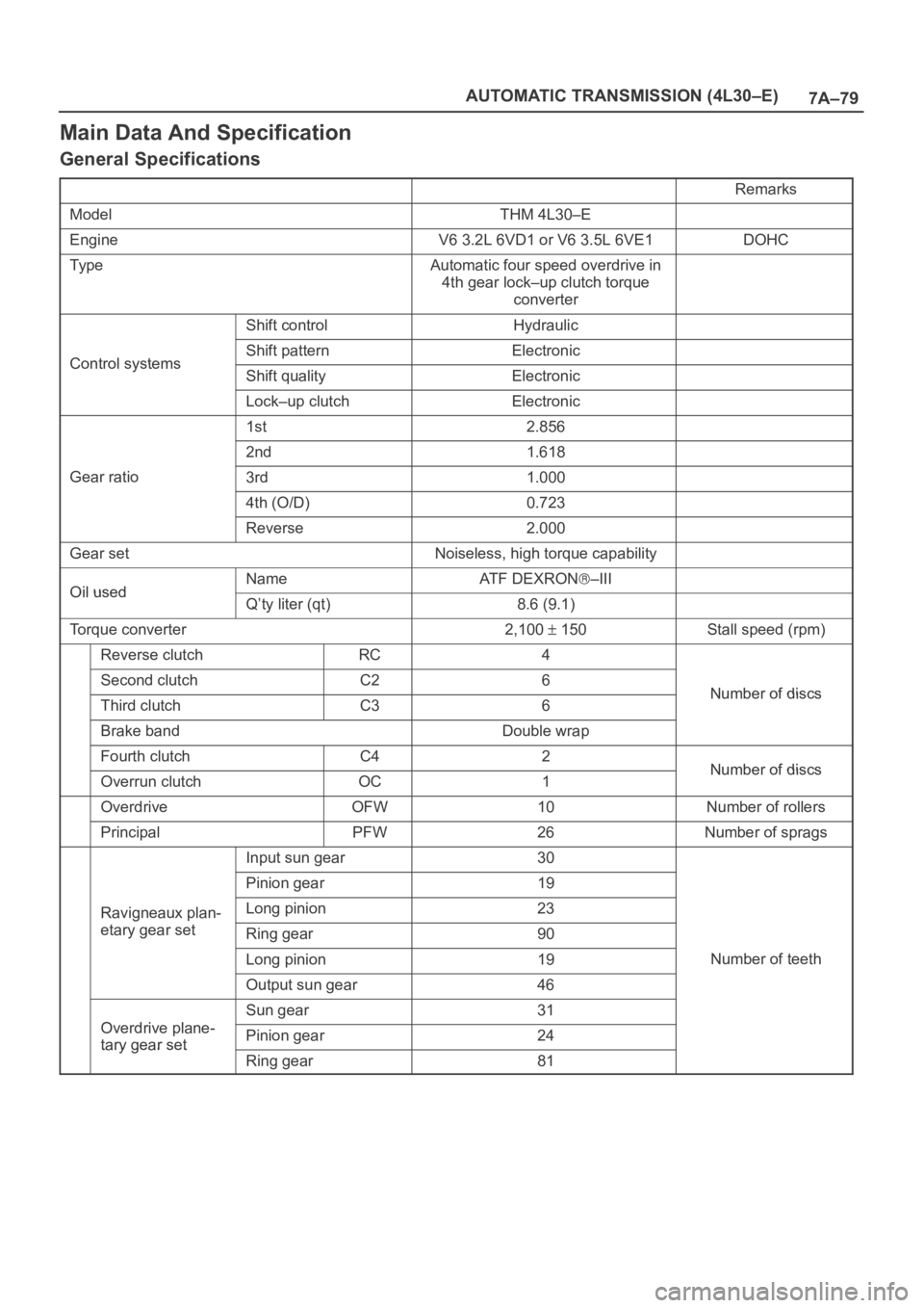
Main Data And Specification
General Specifications
Remarks
ModelTHM 4L30–E
EngineV6 3.2L 6VD1 or V6 3.5L 6VE1DOHC
Ty p eAutomatic four speed overdrive in
4th gear lock–up clutch torque
converter
Shift controlHydraulic
Control systemsShift patternElectronicControl systemsShift qualityElectronic
Lock–up clutchElectronic
1st2.856
2nd1.618
Gear ratio3rd1.000
4th (O/D)0.723
Reverse2.000
Gear setNoiseless, high torque capability
Oil usedNameAT F D E X R O N–IIIOil usedQ’ty liter (qt)8.6 (9.1)
Torque converter2,100 150Stall speed (rpm)
Reverse clutchRC4
Second clutchC26Number of discsThird clutchC36Number of discs
Brake bandDouble wrap
Fourth clutchC42Number of discsOverrun clutchOC1Number of discs
OverdriveOFW10Number of rollers
PrincipalPFW26Number of sprags
Input sun gear30
Pinion gear19
Ravigneaux plan-Long pinion23g
etary gear setRing gear90
Long pinion19Number of teeth
Output sun gear46
Odi l
Sun gear31
Overdrive plane-
tary gear setPinion gear24tary gear set
Ring gear81