1998 OPEL FRONTERA lock
[x] Cancel search: lockPage 5652 of 6000
6E–223 4JX1–TC ENGINE DRIVEABILITY AND EMISSIONS
Weather-Pack Connector
To o l s R e q u i r e d
5-8840-0388-0 Weather-Pack II Terminal Remover
Removal Procedure
A Weather-Pack connector can be identified by a rubber
seal at the rear of the connector. This engine room
connector protects against moisture and dirt, which could
from oxidation and deposits on the terminals. This
protection is important, because of the low voltage and
the low amperage found in the electronic systems.
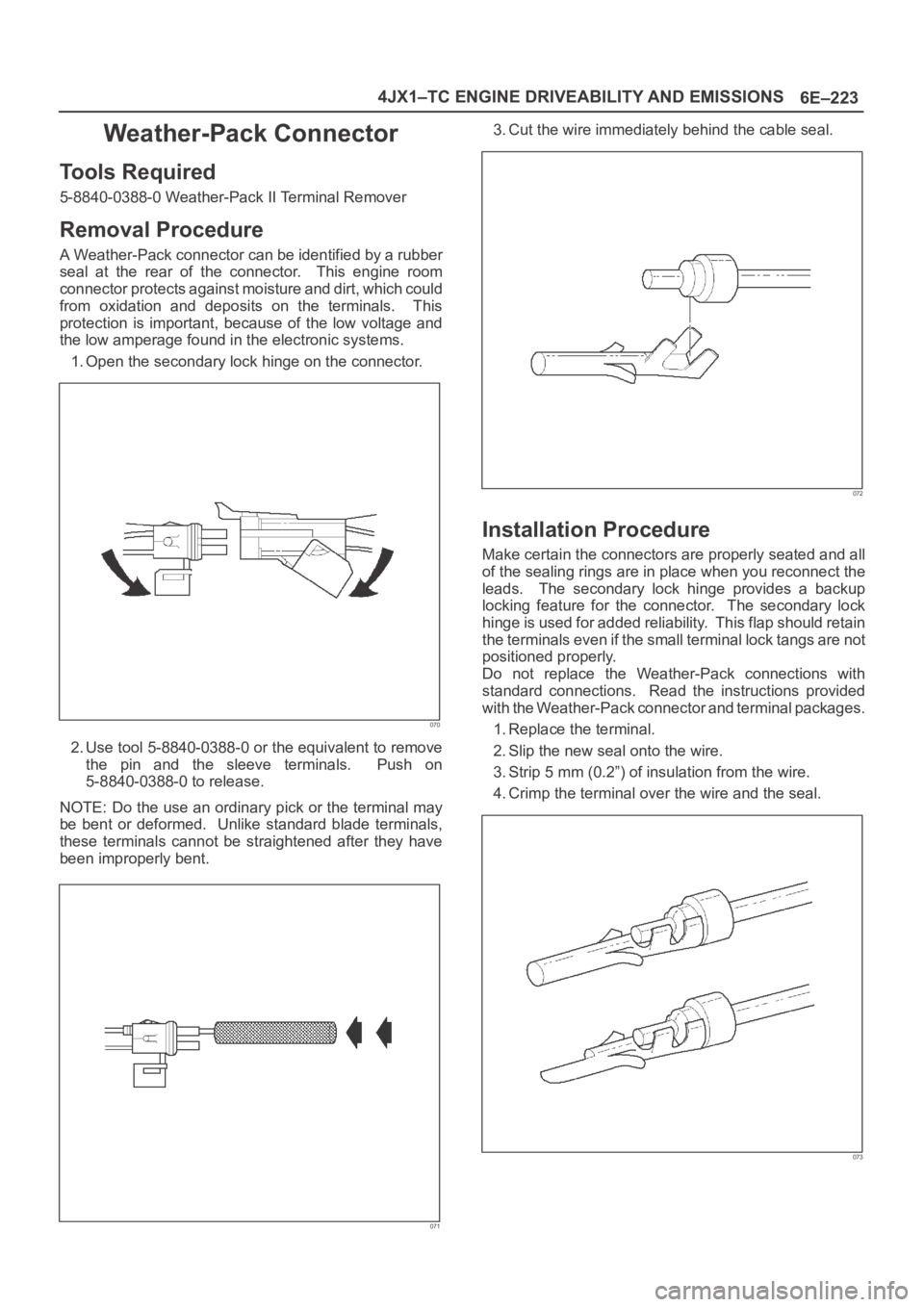
1. Open the secondary lock hinge on the connector.
070
2. Use tool 5-8840-0388-0 or the equivalent to remove
the pin and the sleeve terminals. Push on
5-8840-0388-0 to release.
NOTE: Do the use an ordinary pick or the terminal may
be bent or deformed. Unlike standard blade terminals,
these terminals cannot be straightened after they have
been improperly bent.
071
3. Cut the wire immediately behind the cable seal.
072
Installation Procedure
Make certain the connectors are properly seated and all
of the sealing rings are in place when you reconnect the
leads. The secondary lock hinge provides a backup
locking feature for the connector. The secondary lock
hinge is used for added reliability. This flap should retain
the terminals even if the small terminal lock tangs are not
positioned properly.
Do not replace the Weather-Pack connections with
standard connections. Read the instructions provided
with the Weather-Pack connector and terminal packages.
1. Replace the terminal.
2. Slip the new seal onto the wire.
3. Strip 5 mm (0.2”) of insulation from the wire.
4. Crimp the terminal over the wire and the seal.
073
Page 5653 of 6000
6E–224
4JX1–TC ENGINE DRIVEABILITY AND EMISSIONS
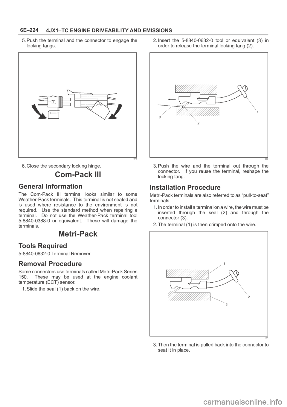
5. Push the terminal and the connector to engage the
locking tangs.
070
6. Close the secondary locking hinge.
Com-Pack III
General Information
The Com-Pack III terminal looks similar to some
Weather-Pack terminals. This terminal is not sealed and
is used where resistance to the environment is not
required. Use the standard method when repairing a
terminal. Do not use the Weather-Pack terminal tool
5-8840-0388-0 or equivalent. These will damage the
terminals.
Metri-Pack
To o l s R e q u i r e d
5-8840-0632-0 Terminal Remover
Removal Procedure
S o m e c o n n e c t o r s u s e t e r m i n a l s c a l l e d M e t r i - P a c k S e r i e s
150. These may be used at the engine coolant
temperature (ECT) sensor.
1. Slide the seal (1) back on the wire.2. Insert the 5-8840-0632-0 tool or equivalent (3) in
order to release the terminal locking tang (2).
060
3. Push the wire and the terminal out through the
connector. If you reuse the terminal, reshape the
locking tang.
Installation Procedure
Metri-Pack terminals are also referred to as “pull-to-seat”
terminals.
1. In order to install a terminal on a wire, the wire must be
inserted through the seal (2) and through the
connector (3).
2. The terminal (1) is then crimped onto the wire.
061
3. Then the terminal is pulled back into the connector to
seat it in place.
Page 5661 of 6000
6F – 2 ENGINE EXHAUST
GENERAL DESCRIPTION
150RW070
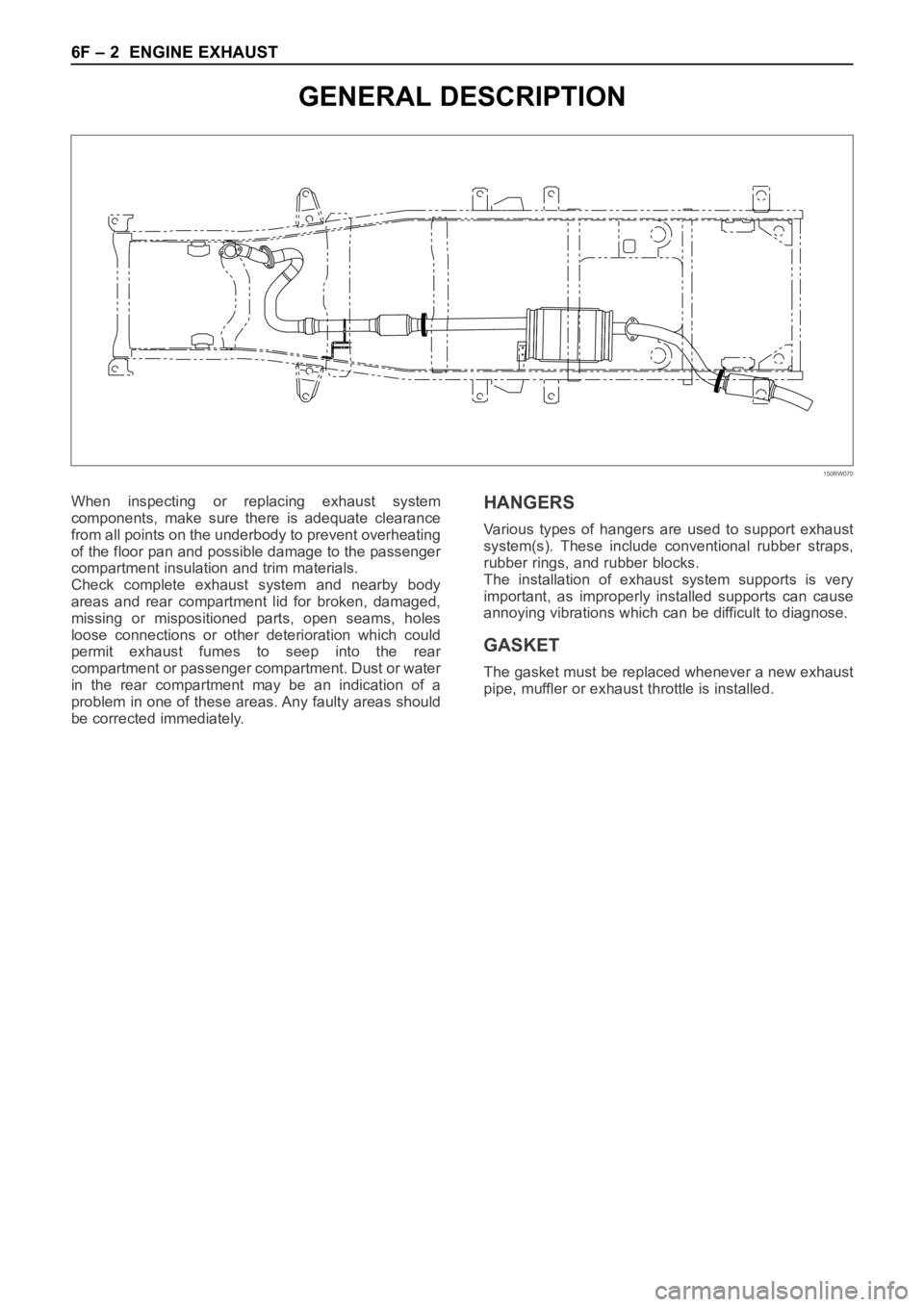
When inspecting or replacing exhaust system
components, make sure there is adequate clearance
from all points on the underbody to prevent overheating
of the floor pan and possible damage to the passenger
compartment insulation and trim materials.
Check complete exhaust system and nearby body
areas and rear compartment lid for broken, damaged,
missing or mispositioned parts, open seams, holes
loose connections or other deterioration which could
permit exhaust fumes to seep into the rear
compartment or passenger compartment. Dust or water
in the rear compartment may be an indication of a
problem in one of these areas. Any faulty areas should
be corrected immediately.HANGERS
Various types of hangers are used to support exhaust
system(s). These include conventional rubber straps,
rubber rings, and rubber blocks.
The installation of exhaust system supports is very
important, as improperly installed supports can cause
annoying vibrations which can be difficult to diagnose.
GASKET
The gasket must be replaced whenever a new exhaust
pipe, muffler or exhaust throttle is installed.
Page 5672 of 6000
ENGINE LUBRICATION 6G – 5
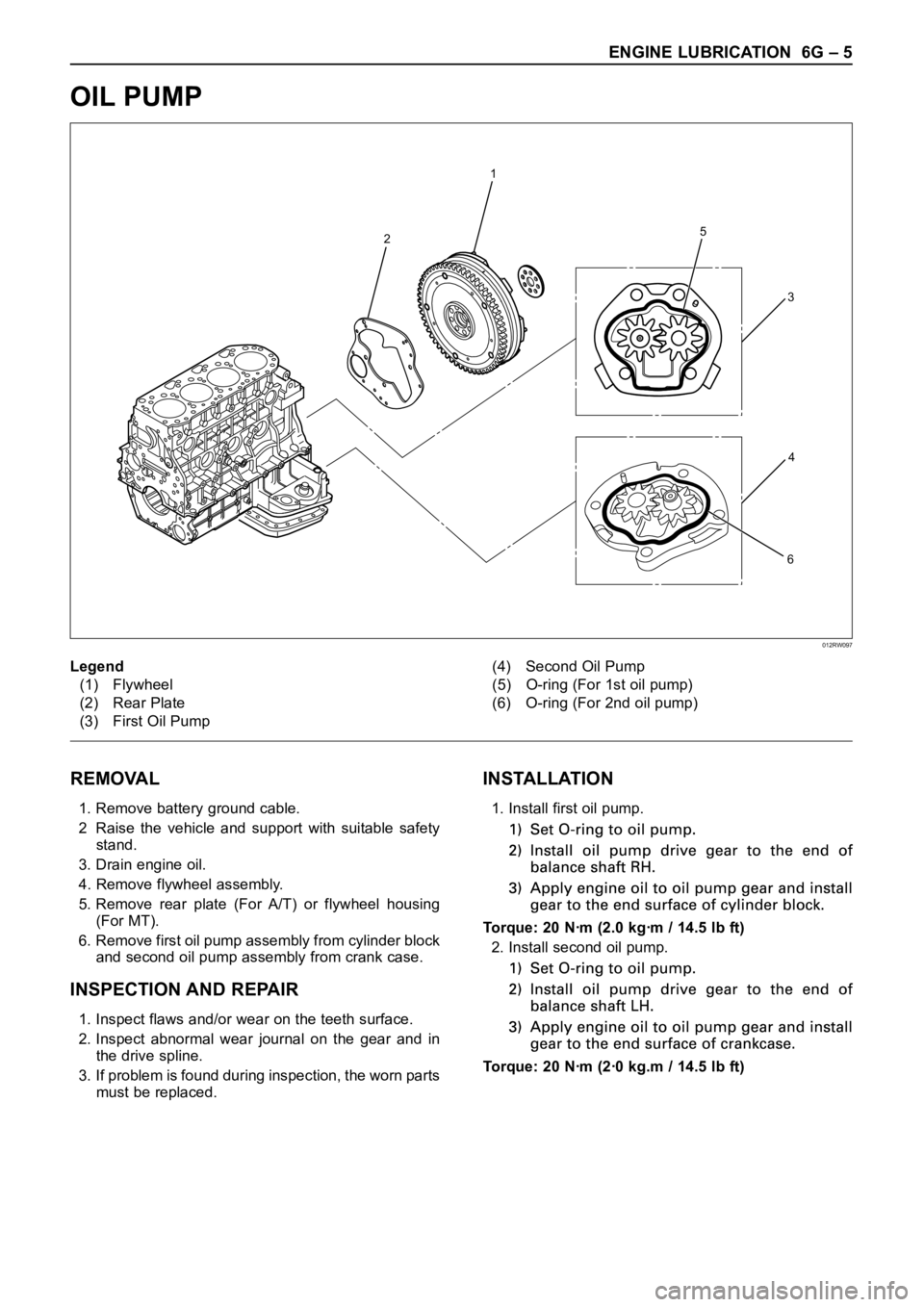
OIL PUMP
REMOVAL
1. Remove battery ground cable.
2 Raise the vehicle and support with suitable safety
stand.
3. Drain engine oil.
4. Remove flywheel assembly.
5. Remove rear plate (For A/T) or flywheel housing
(For MT).
6. Remove first oil pump assembly from cylinder block
and second oil pump assembly from crank case.
INSPECTION AND REPAIR
1. Inspect flaws and/or wear on the teeth surface.
2. Inspect abnormal wear journal on the gear and in
the drive spline.
3. If problem is found during inspection, the worn parts
must be replaced.
INSTALLATION
1. Install first oil pump.
Torque: 20 Nꞏm (2.0 kgꞏm / 14.5 lb ft)
2. Install second oil pump.
Torque: 20 Nꞏm (2ꞏ0 kg.m / 14.5 lb ft)
2
1
5
6
3
4
Legend
(1) Flywheel
(2) Rear Plate
(3) First Oil Pump(4) Second Oil Pump
(5) O-ring (For 1st oil pump)
(6) O-ring (For 2nd oil pump)
012RW097
Page 5690 of 6000
7A–1 AUTOMATIC TRANSMISSION (4L30–E)
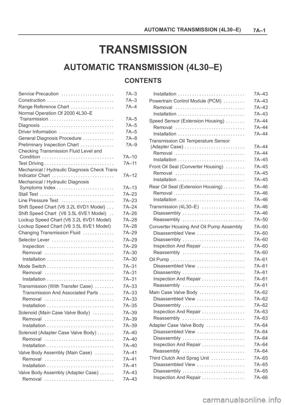
TRANSMISSION
AUTOMATIC TRANSMISSION (4L30–E)
CONTENTS
Service Precaution 7A–3. . . . . . . . . . . . . . . . . . . . . .
Construction 7A–3. . . . . . . . . . . . . . . . . . . . . . . . . . . .
Range Reference Chart 7A–4. . . . . . . . . . . . . . . . . .
Normal Operation Of 2000 4L30–E
Transmission 7A–5. . . . . . . . . . . . . . . . . . . . . . . . . . .
Diagnosis 7A–5. . . . . . . . . . . . . . . . . . . . . . . . . . . . . .
Driver Information 7A–5. . . . . . . . . . . . . . . . . . . . . . .
General Diagnosis Procedure 7A–8. . . . . . . . . . . . .
Preliminary Inspection Chart 7A–9. . . . . . . . . . . . . .
Checking Transmission Fluid Level and
Condition 7A–10. . . . . . . . . . . . . . . . . . . . . . . . . . . . . .
Test Driving 7A–11. . . . . . . . . . . . . . . . . . . . . . . . . . . . .
Mechanical / Hydraulic Diagnosis Check Trans
Indicator Chart 7A–12. . . . . . . . . . . . . . . . . . . . . . . . . .
Mechanical / Hydraulic Diagnosis
Symptoms Index 7A–13. . . . . . . . . . . . . . . . . . . . . . . .
Stall Test 7A–23. . . . . . . . . . . . . . . . . . . . . . . . . . . . . . .
Line Pressure Test 7A–23. . . . . . . . . . . . . . . . . . . . . .
Shift Speed Chart (V6 3.2L 6VD1 Model) 7A–24. . .
Shift Speed Chart (V6 3.5L 6VE1 Model) 7A–26. .
Lockup Speed Chart (V6 3.2L 6VD1 Model) 7A–28
Lockup Speed Chart (V6 3.5L 6VE1 Model) 7A–28
Changing Transmission Fluid 7A–29. . . . . . . . . . . . .
Selector Lever 7A–29. . . . . . . . . . . . . . . . . . . . . . . . . .
Inspection 7A–29. . . . . . . . . . . . . . . . . . . . . . . . . . . .
Removal 7A–30. . . . . . . . . . . . . . . . . . . . . . . . . . . . .
Installation 7A–30. . . . . . . . . . . . . . . . . . . . . . . . . . . .
Mode Switch 7A–31. . . . . . . . . . . . . . . . . . . . . . . . . . . .
Removal 7A–31. . . . . . . . . . . . . . . . . . . . . . . . . . . . .
Installation 7A–31. . . . . . . . . . . . . . . . . . . . . . . . . . . .
Transmission (With Transfer Case) 7A–33. . . . . . . .
Transmission And Associated Parts 7A–33. . . . . .
Removal 7A–33. . . . . . . . . . . . . . . . . . . . . . . . . . . . .
Installation 7A–35. . . . . . . . . . . . . . . . . . . . . . . . . . . .
Solenoid (Main Case Valve Body) 7A–39. . . . . . . . .
Removal 7A–39. . . . . . . . . . . . . . . . . . . . . . . . . . . . .
Installation 7A–39. . . . . . . . . . . . . . . . . . . . . . . . . . . .
Solenoid (Adapter Case Valve Body) 7A–40. . . . . . .
Removal 7A–40. . . . . . . . . . . . . . . . . . . . . . . . . . . . .
Installation 7A–40. . . . . . . . . . . . . . . . . . . . . . . . . . . .
Valve Body Assembly (Main Case) 7A–41. . . . . . . .
Removal 7A–41. . . . . . . . . . . . . . . . . . . . . . . . . . . . .
Installation 7A–41. . . . . . . . . . . . . . . . . . . . . . . . . . . .
Valve Body Assembly (Adapter Case) 7A–43. . . . . .
Removal 7A–43. . . . . . . . . . . . . . . . . . . . . . . . . . . . . Installation 7A–43. . . . . . . . . . . . . . . . . . . . . . . . . . . .
Powertrain Control Module (PCM) 7A–43. . . . . . . . .
Removal 7A–43. . . . . . . . . . . . . . . . . . . . . . . . . . . . .
Installation 7A–43. . . . . . . . . . . . . . . . . . . . . . . . . . . .
Speed Sensor (Extension Housing) 7A–44. . . . . . . .
Removal 7A–44. . . . . . . . . . . . . . . . . . . . . . . . . . . . .
Installation 7A–44. . . . . . . . . . . . . . . . . . . . . . . . . . . .
Transmission Oil Temperature Sensor
(Adapter Case) 7A–44. . . . . . . . . . . . . . . . . . . . . . . . .
Removal 7A–44. . . . . . . . . . . . . . . . . . . . . . . . . . . . .
Installation 7A–45. . . . . . . . . . . . . . . . . . . . . . . . . . . .
Front Oil Seal (Converter Housing) 7A–45. . . . . . . .
Removal 7A–45. . . . . . . . . . . . . . . . . . . . . . . . . . . . .
Installation 7A–45. . . . . . . . . . . . . . . . . . . . . . . . . . . .
Rear Oil Seal (Extension Housing) 7A–46. . . . . . . . .
Removal 7A–46. . . . . . . . . . . . . . . . . . . . . . . . . . . . .
Installation 7A–46. . . . . . . . . . . . . . . . . . . . . . . . . . . .
Transmission (4L30–E) 7A–46. . . . . . . . . . . . . . . . . .
Disassembly 7A–46. . . . . . . . . . . . . . . . . . . . . . . . . .
Reassembly 7A–50. . . . . . . . . . . . . . . . . . . . . . . . . .
Converter Housing And Oil Pump Assembly 7A–60
Disassembled View 7A–60. . . . . . . . . . . . . . . . . . . .
Disassembly 7A–60. . . . . . . . . . . . . . . . . . . . . . . . . .
Inspection And Repair 7A–60. . . . . . . . . . . . . . . . . .
Reassembly 7A–60. . . . . . . . . . . . . . . . . . . . . . . . . .
Oil Pump 7A–61. . . . . . . . . . . . . . . . . . . . . . . . . . . . . . .
Disassembled View 7A–61. . . . . . . . . . . . . . . . . . . .
Disassembly 7A–61. . . . . . . . . . . . . . . . . . . . . . . . . .
Inspection And Repair 7A–61. . . . . . . . . . . . . . . . . .
Reassembly 7A–61. . . . . . . . . . . . . . . . . . . . . . . . . .
Main Case Valve Body 7A–62. . . . . . . . . . . . . . . . . . .
Disassembled View 7A–62. . . . . . . . . . . . . . . . . . . .
Disassembly 7A–62. . . . . . . . . . . . . . . . . . . . . . . . . .
Inspection And Repair 7A–63. . . . . . . . . . . . . . . . . .
Reassembly 7A–63. . . . . . . . . . . . . . . . . . . . . . . . . .
Adapter Case Valve Body 7A–64. . . . . . . . . . . . . . . .
Disassembled View 7A–64. . . . . . . . . . . . . . . . . . . .
Disassembly 7A–64. . . . . . . . . . . . . . . . . . . . . . . . . .
Inspection And Repair 7A–64. . . . . . . . . . . . . . . . . .
Reassembly 7A–64. . . . . . . . . . . . . . . . . . . . . . . . . .
Third Clutch And Sprag Unit 7A–65. . . . . . . . . . . . . .
Disassembled View 7A–65. . . . . . . . . . . . . . . . . . . .
Disassembly 7A–65. . . . . . . . . . . . . . . . . . . . . . . . . .
Inspection And Repair 7A–66. . . . . . . . . . . . . . . . . .
Page 5692 of 6000
7A–3 AUTOMATIC TRANSMISSION (4L30–E)
Service Precaution
WARNING: IF SO EQUIPPED WITH A
SUPPLEMENTAL RESTRAINT SYSTEM (SRS),
REFER TO THE SRS COMPONENT AND WIRING
LOCATION VIEW IN ORDER TO DETERMINE
WHETHER YOU ARE PERFORMING SERVICE ON OR
NEAR THE SRS COMPONENTS OR THE SRS
WIRING. WHEN YOU ARE PERFORMING SERVICE
ON OR NEAR THE SRS COMPONENTS OR THE SRS
WIRING, REFER TO THE SRS SERVICE
INFORMATION. FAILURE TO FOLLOW WARNINGS
COULD RESULT IN POSSIBLE AIR BAG
DEPLOYMENT, PERSONAL INJURY, OR
OTHERWISE UNNEEDED SRS SYSTEM REPAIRS.CAUTION: Always use the correct fastener in the
proper location. When you replace a fastener, use
ONLY the exact part number for that application.
ISUZU will call out those fasteners that require a
replacement after removal. ISUZU will also call out
the fasteners that require thread lockers or thread
sealant. UNLESS OTHERWISE SPECIFIED, do not
use supplemental coatings (Paints, greases, or other
corrosion inhibitors) on threaded fasteners or
fastener joint interfaces. Generally, such coatings
adversely affect the fastener torque and the joint
clamping force, and may damage the fastener. When
you install fasteners, use the correct tightening
sequence and specifications. Following these
instructions can help you avoid damage to parts and
systems.
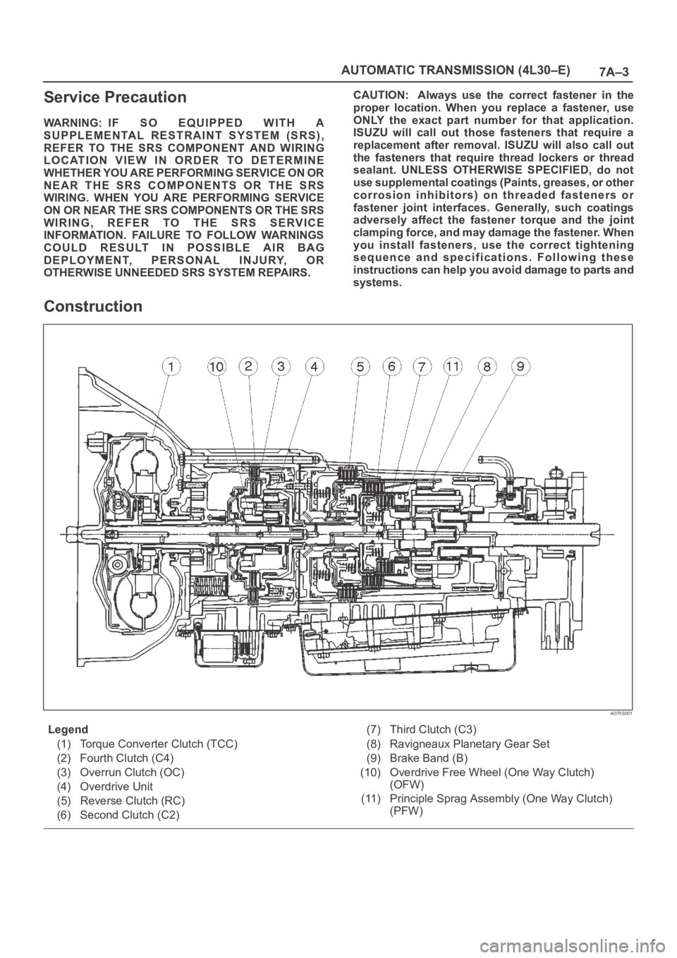
Construction
A07RS001
Legend
(1) Torque Converter Clutch (TCC)
(2) Fourth Clutch (C4)
(3) Overrun Clutch (OC)
(4) Overdrive Unit
(5) Reverse Clutch (RC)
(6) Second Clutch (C2)(7) Third Clutch (C3)
(8) Ravigneaux Planetary Gear Set
(9) Brake Band (B)
(10) Overdrive Free Wheel (One Way Clutch)
(OFW)
(11) Principle Sprag Assembly (One Way Clutch)
(PFW)
Page 5703 of 6000
7A–14
AUTOMATIC TRANSMISSION (4L30–E)
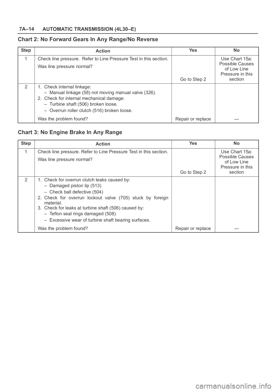
Chart 2: No Forward Gears In Any Range/No Reverse
StepActionYe sNo
1Check line pressure. Refer to Line Pressure Test in this section.
Was line pressure normal?
Go to Step 2
Use Chart 15a:
Possible Causes
of Low Line
Pressure in this
section
21. Check internal linkage:
– Manual linkage (58) not moving manual valve (326).
2. Check for internal mechanical damage:
– Turbine shaft (506) broken loose.
– Overrun roller clutch (516) broken loose.
Was the problem found?
Repair or replace—
Chart 3: No Engine Brake In Any Range
StepActionYe sNo
1Check line pressure. Refer to Line Pressure Test in this section.
Was line pressure normal?
Go to Step 2
Use Chart 15a:
Possible Causes
of Low Line
Pressure in this
section
21. Check for overrun clutch leaks caused by:
– Damaged piston lip (513)
– Check ball defective (504)
2. Check for overrun lockout valve (705) stuck by foreign
material.
3. Check for leaks at turbine shaft (506) caused by:
– Teflon seal rings damaged (508)
– Excessive wear of turbine shaft bearing surfaces.
Was the problem found?
Repair or replace—
Page 5709 of 6000
7A–20
AUTOMATIC TRANSMISSION (4L30–E)
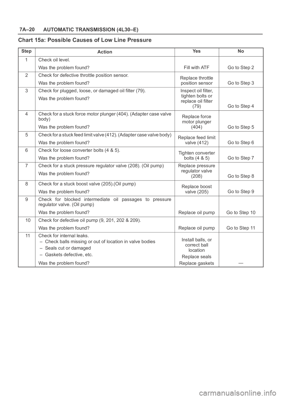
Chart 15a: Possible Causes of Low Line Pressure
StepActionYe sNo
1Check oil level.
Was the problem found?
Fill with ATFGo to Step 2
2Check for defective throttle position sensor.
Was the problem found?Replace throttle
position sensor
Go to Step 3
3Check for plugged, loose, or damaged oil filter (79).
Was the problem found?Inspect oil filter,
tighten bolts or
replace oil filter
(79)
Go to Step 4
4Check for a stuck force motor plunger (404). (Adapter case valve
body)
Was the problem found?Replace force
motor plunger
(404)
Go to Step 5
5Check for a stuck feed limit valve (412). (Adapter case valve body)
Was the problem found?Replace feed limit
valve (412)
Go to Step 6
6Check for loose converter bolts (4 & 5).
Was the problem found?Tighten converter
bolts (4 & 5)
Go to Step 7
7Check for a stuck pressure regulator valve (208). (Oil pump)
Was the problem found?Replace pressure
regulator valve
(208)
Go to Step 8
8Check for a stuck boost valve (205).(Oil pump)
Was the problem found?Replace boost
valve (205)
Go to Step 9
9Check for blocked intermediate oil passages to pressure
regulator valve. (Oil pump)
Was the problem found?
Replace oil pumpGo to Step 10
10Check for defective oil pump (9, 201, 202 & 209).
Was the problem found?
Replace oil pumpGo to Step 11
11Check for internal leaks.
– Check balls missing or out of location in valve bodies
– Seals cut or damaged
– Gaskets defective, etc.
Was the problem found?Install balls, or
correct ball
location
Replace seals
Replace gaskets
—