Page 2374 of 6000
7B–56MANUAL TRANSMISSION
24. Install the interlock parts.
1. Using a screwdriver and hammer, 2 new shift rod
snap rings to the 1st–2nd and 3rd–4th shift rod.
226RW051
2. Install the 3 shift detent ball and springs to the
intermediate plate.
226RW049
3. Clean up the plug hole.
4. Apply sealant to the plug threads.
sealant: THREE BOND 1344 or equivalent5. Using a torx socket wrench(T40), install and
torque the 4 plugs.
Torque: 19 Nꞏm (1.9 kgꞏm/14 lb ft)
226RW050
25. Install mainshaft assembly.
NOTE: Coat all parts with gear oil before installing them.
1. Using a plastic hammer, tap the 5th-reverse shift
rod at the reverse shift.
226RW180
Page 2377 of 6000
MANUAL TRANSMISSION7B–59
28. Install the reverse idle gear.
1. Install the reverse idle gear and reverse idle gear
shaft.
NOTE:
Insert the reverse idle gear shaft with the slot toward
rear.
Install the reverse idle gear with the reverse shift arm
No.2.
226RW019
29. Install the bearing plate.
1. Align the bearing plate to groove of the reverse
idle gear shaft.
Torque: 13 Nꞏm (1.3 kgꞏm/113 lb in)
226RW016
30. Install the 5th gear thrust washer.
1. Install the 5th gear thrust washer pin to the
counter gear shaft.
2. Install the 5th gear thrust washer to the counter
gear shaft.
NOTE: Thrust washer must be assembled with the
chamfered face of the washer toward the front.
226RW185
31. Install the counter 5th gear.
1. Install the 3 inserts and 3 compression springs to
the reverse block ring.
Reference: Push the 3 inserts with the 3 com-
pression springs to the reverse synchronizer
ring.
226RW120
Page 2378 of 6000
7B–60MANUAL TRANSMISSION
2. Install the synchronizer outer ring, synchronizer
cone ring, and synchronizer pull ring to the
reverse block ring.
226RW121
3. Turn to 30 degree the reverse synchronizer pull
ring.
226RW080
4. Install the hub sleeve No.3 and reverse block ring
set to the counter 5th gear.
NOTE: Check the hub sleeve No.3 direction, as shown.
Reference: While pushing the 3 inserts,
install the synchronizer ring assembly to the
hub sleeve No.3.
226RW184
5. Slide the hub sleeve No.3.
226RW123
Page 2379 of 6000
MANUAL TRANSMISSION7B–61
6. Install the counter 5th gear bearing, counter 5th
gear and reverse block ring set to the counter
gear shaft, through the 5th reverse shift arm to the
5th reverse shift rod.
220RW101
7. Using installer 5–8840–2552–0 (J–42796) and a
press, install counter 5th gear spline piece.
NOTE:
Align the projection of the cone ring to the holes of the
5th gear spline piece.
Check that the gear rotates smoothly.
226RW193
8. Using thickness gauge, measure the counter 5th
gear thrust clearance.
Standard: 0.10 – 0.35mm (0.004 – 0.014 in)
220RW100
9. Select a snap ring that will allow minimum axial
play.
Mark
Thickness
A2.80 – 2.85 (0.110 – 0.112 in)
B2.85 – 2.90 (0.112 – 0.114 in)
C2.90 – 2.95 (0.114 – 0.116 in)
D2.95 – 3.00 (0.116 – 0.118 in)
E3.00 – 3.05 (0.118 – 0.120 in)
F3.05 – 3.10 (0.120 – 0.122 in)
G3.10 – 3.15 (0.122 – 0.124 in)
226RW027
Page 2381 of 6000
MANUAL TRANSMISSION7B–63
3. Stand the transmission by the wood blocks.
4. Using a plastic hammer, tap the transmission
case and attach it to the intermediate plate.
NOTE: Be careful not to add over force to bearing.
220RW022
5. Using a snap ring expander, install the front
bearing shaft snap ring (1) and counter gear shaft
bearing snap ring (2).
226RW004
6. Turn over the transmission.
35. Install the front cover.
1. Clean up the fitting surface.
2. Apply recommended liquid gasket (THREE
BOND 1281 or equivalent), as shown.NOTE:
Don’t dry the liquid gasket.
220RW025
3. Clean up and dry the bolts.
4. Apply thread sealant (THREE BOND 1344 or
equivalent) to the 8 bolts.
5. Using 8 bolts, install the front cover to the
transmission case.
Torque: 17 Nꞏm (1.7 kgꞏm/12 lb ft)
NOTE:
Tighten the all bolts evenly.
Be careful not to damage the oil seal.
220RW018
Page 2511 of 6000

CLUTCH7C–1
TRANSMISSION
CLUTCH
CONTENTS
Service Precaution 7C–1. . . . . . . . . . . . . . . . . . . . . .
General Description 7C–2. . . . . . . . . . . . . . . . . . . . .
Diagnosis 7C–8. . . . . . . . . . . . . . . . . . . . . . . . . . . . . .
Clutch Assembly 7C–9. . . . . . . . . . . . . . . . . . . . . . . .
Clutch Assembly and Associated Parts 7C–9. . .
Removal 7C–9. . . . . . . . . . . . . . . . . . . . . . . . . . . . .
Inspection and Repair 7C–10. . . . . . . . . . . . . . . . . .
Installation 7C–15. . . . . . . . . . . . . . . . . . . . . . . . . . . .
Clutch Control 7C–17. . . . . . . . . . . . . . . . . . . . . . . . . .
Clutch Control Parts 7C–17. . . . . . . . . . . . . . . . . . .
Removal 7C–18. . . . . . . . . . . . . . . . . . . . . . . . . . . . .
Inspection and Repair 7C–18. . . . . . . . . . . . . . . . . .
Installation 7C–19. . . . . . . . . . . . . . . . . . . . . . . . . . . .
Adjustment 7C–19. . . . . . . . . . . . . . . . . . . . . . . . . . .
Master Cylinder 7C–22. . . . . . . . . . . . . . . . . . . . . . . . .
Disassembled View 7C–22. . . . . . . . . . . . . . . . . . . .
Disassembly 7C–23. . . . . . . . . . . . . . . . . . . . . . . . . . Inspection and Repair 7C–23. . . . . . . . . . . . . . . . . .
Reassembly 7C–23. . . . . . . . . . . . . . . . . . . . . . . . . .
Slave Cylinder 7C–24. . . . . . . . . . . . . . . . . . . . . . . . . .
Disassembled View 7C–24. . . . . . . . . . . . . . . . . . . .
Disassembly 7C–24. . . . . . . . . . . . . . . . . . . . . . . . . .
Inspection and Repair 7C–24. . . . . . . . . . . . . . . . . .
Reassembly 7C–25. . . . . . . . . . . . . . . . . . . . . . . . . .
Damper Cylinder 7C–26. . . . . . . . . . . . . . . . . . . . . . . .
Disassembled View 7C–26. . . . . . . . . . . . . . . . . . . .
Disassembly 7C–26. . . . . . . . . . . . . . . . . . . . . . . . . .
Inspection and Repair 7C–26. . . . . . . . . . . . . . . . . .
Reassembly 7C–26. . . . . . . . . . . . . . . . . . . . . . . . . .
Main Data and Specifications 7C–27. . . . . . . . . . . . .
General Specifications 7C–27. . . . . . . . . . . . . . . . .
Torque Specifications 7C–27. . . . . . . . . . . . . . . . . .
Special Tools 7C–30. . . . . . . . . . . . . . . . . . . . . . . . . . .
Service Precaution
WARNING: IF SO EQUIPPED WITH A
SUPPLEMENTAL RESTRAINT SYSTEM (SRS),
REFER TO THE SRS COMPONENT AND WIRING
LOCATION VIEW IN ORDER TO DETERMINE
WHETHER YOU ARE PERFORMING SERVICE ON OR
NEAR THE SRS COMPONENTS OR THE SRS
WIRING. WHEN YOU ARE PERFOMING SERVICE ON
OR NEAR THE SRS COMPONENTS OR THE SRS
WIRING, REFER TO THE SRS SERVICE
INFORMATION. FAILURE TO FOLLOW WARNINGS
COULD RESULT IN POSSIBLE AIR BAG
DEPLOYMENT, PERSONAL INJURY, OR
OTHERWISE UNNEEDED SRS SYSTEM REPAIRS. CAUTION: Always use the correct fastner in the
proper location. When you reolace a fastener, use
ONLY the exact part number for that application.
ISUZU will call out those fasteners that requir a
replacement after removal. ISUZU will also call out
the fasteners that requir thread lockers or thread
sealant. UNLESS OTHERWISE SPECIFIED , do not
use supplemental coatings (Paints, greases, or other
corrosion inhibitors) on threaded fastners or fastner
joint interfaces. Generally,such coatings adversely
affect the fastner torque and the joint clamping force,
and may damage the fastner. When you install
fasteners, use the correct tightening sequence and
specifications. Following these instructions can
help you avoid damage to parts and systems.
Page 2517 of 6000

7C–8CLUTCH
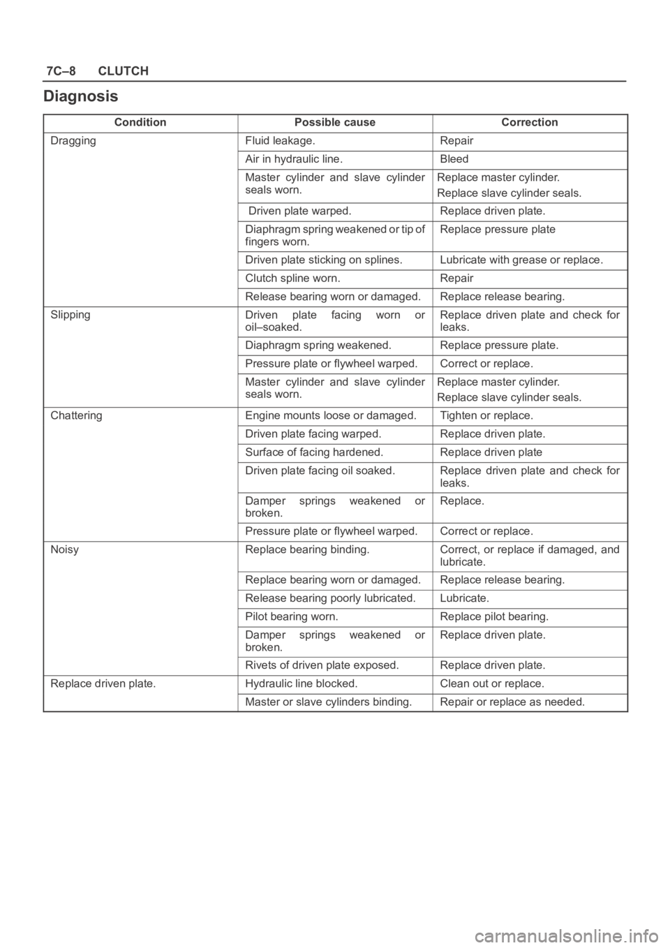
Diagnosis
ConditionPossible causeCorrection
DraggingFluid leakage.Repair
Air in hydraulic line.Bleed
Master cylinder and slave cylinder
seals worn. Replace master cylinder.
Replace slave cylinder seals.
Driven plate warped.Replace driven plate.
Diaphragm spring weakened or tip of
fingers worn. Replace pressure plate
Driven plate sticking on splines.Lubricate with grease or replace.
Clutch spline worn. Repair
Release bearing worn or damaged.Replace release bearing.
SlippingDriven plate facing worn or
oil–soaked.Replace driven plate and check for
leaks.
Diaphragm spring weakened.Replace pressure plate.
Pressure plate or flywheel warped.Correct or replace.
Master cylinder and slave cylinder
seals worn.Replace master cylinder.
Replace slave cylinder seals.
ChatteringEngine mounts loose or damaged.Tighten or replace.
Driven plate facing warped.Replace driven plate.
Surface of facing hardened.Replace driven plate
Driven plate facing oil soaked. Replace driven plate and check for
leaks.
Damper springs weakened or
broken. Replace.
Pressure plate or flywheel warped.Correct or replace.
NoisyReplace bearing binding.Correct, or replace if damaged, and
lubricate.
Replace bearing worn or damaged. Replace release bearing.
Release bearing poorly lubricated. Lubricate.
Pilot bearing worn.Replace pilot bearing.
Damper springs weakened or
broken.Replace driven plate.
Rivets of driven plate exposed.Replace driven plate.
Replace driven plate.Hydraulic line blocked.Clean out or replace.
Master or slave cylinders binding.Repair or replace as needed.
Page 2522 of 6000

CLUTCH7C–13
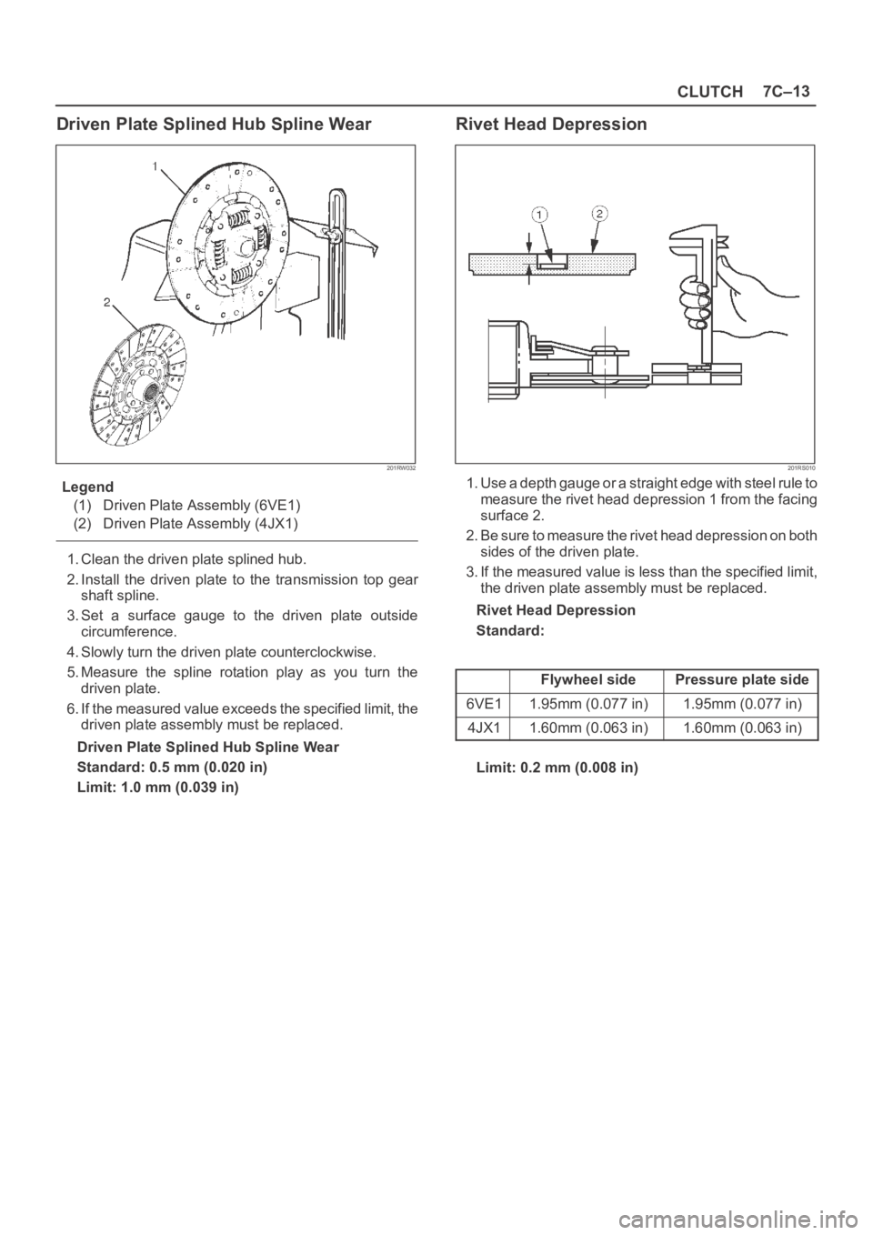
Driven Plate Splined Hub Spline Wear
201RW032
Legend
(1) Driven Plate Assembly (6VE1)
(2) Driven Plate Assembly (4JX1)
1. Clean the driven plate splined hub.
2. Install the driven plate to the transmission top gear
shaft spline.
3. Set a surface gauge to the driven plate outside
circumference.
4. Slowly turn the driven plate counterclockwise.
5. Measure the spline rotation play as you turn the
driven plate.
6. If the measured value exceeds the specified limit, the
driven plate assembly must be replaced.
Driven Plate Splined Hub Spline Wear
Standard: 0.5 mm (0.020 in)
Limit: 1.0 mm (0.039 in)
Rivet Head Depression
201RS010
1. Use a depth gauge or a straight edge with steel rule to
measure the rivet head depression 1 from the facing
surface 2.
2. Be sure to measure the rivet head depression on both
sides of the driven plate.
3. If the measured value is less than the specified limit,
the driven plate assembly must be replaced.
Rivet Head Depression
Standard:
Flywheel sidePressure plate side
6VE11.95mm (0.077 in)1.95mm (0.077 in)
4JX11.60mm (0.063 in)1.60mm (0.063 in)
Limit: 0.2 mm (0.008 in)