1998 OPEL FRONTERA lock
[x] Cancel search: lockPage 2227 of 6000
7A–73 AUTOMATIC TRANSMISSION (4L30–E)
247RW006
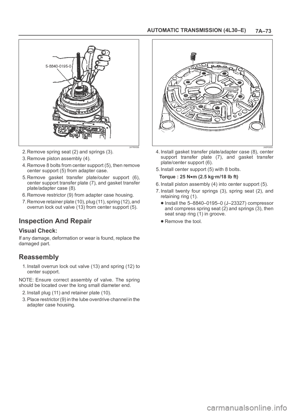
2. Remove spring seat (2) and springs (3).
3. Remove piston assembly (4).
4. Remove 8 bolts from center support (5), then remove
center support (5) from adapter case.
5. Remove gasket transfer plate/outer support (6),
center support transfer plate (7), and gasket transfer
plate/adapter case (8).
6. Remove restrictor (9) from adapter case housing.
7. Remove retainer plate (10), plug (11), spring (12), and
overrun lock out valve (13) from center support (5).
Inspection And Repair
Visual Check:
If any damage, deformation or wear is found, replace the
damaged part.
Reassembly
1. Install overrun lock out valve (13) and spring (12) to
center support.
NOTE: Ensure correct assembly of valve. The spring
should be located over the long small diameter end.
2. Install plug (11) and retainer plate (10).
3. Place restrictor (9) in the lube overdrive channel in the
adapter case housing.
242RS005
4. Install gasket transfer plate/adapter case (8), center
support transfer plate (7), and gasket transfer
plate/center support (6).
5. Install center support (5) with 8 bolts.
Torque : 25 N
m (2.5 kgꞏm/18 lb ft)
6. Install piston assembly (4) into center support (5).
7. Install twenty four springs (3), spring seat (2), and
retaining ring (1).
Install the 5–8840–0195–0 (J–23327) compressor
and compress spring seat (2) and springs (3), then
seat snap ring (1) in groove.
Remove the tool.
Page 2231 of 6000
7A–77 AUTOMATIC TRANSMISSION (4L30–E)
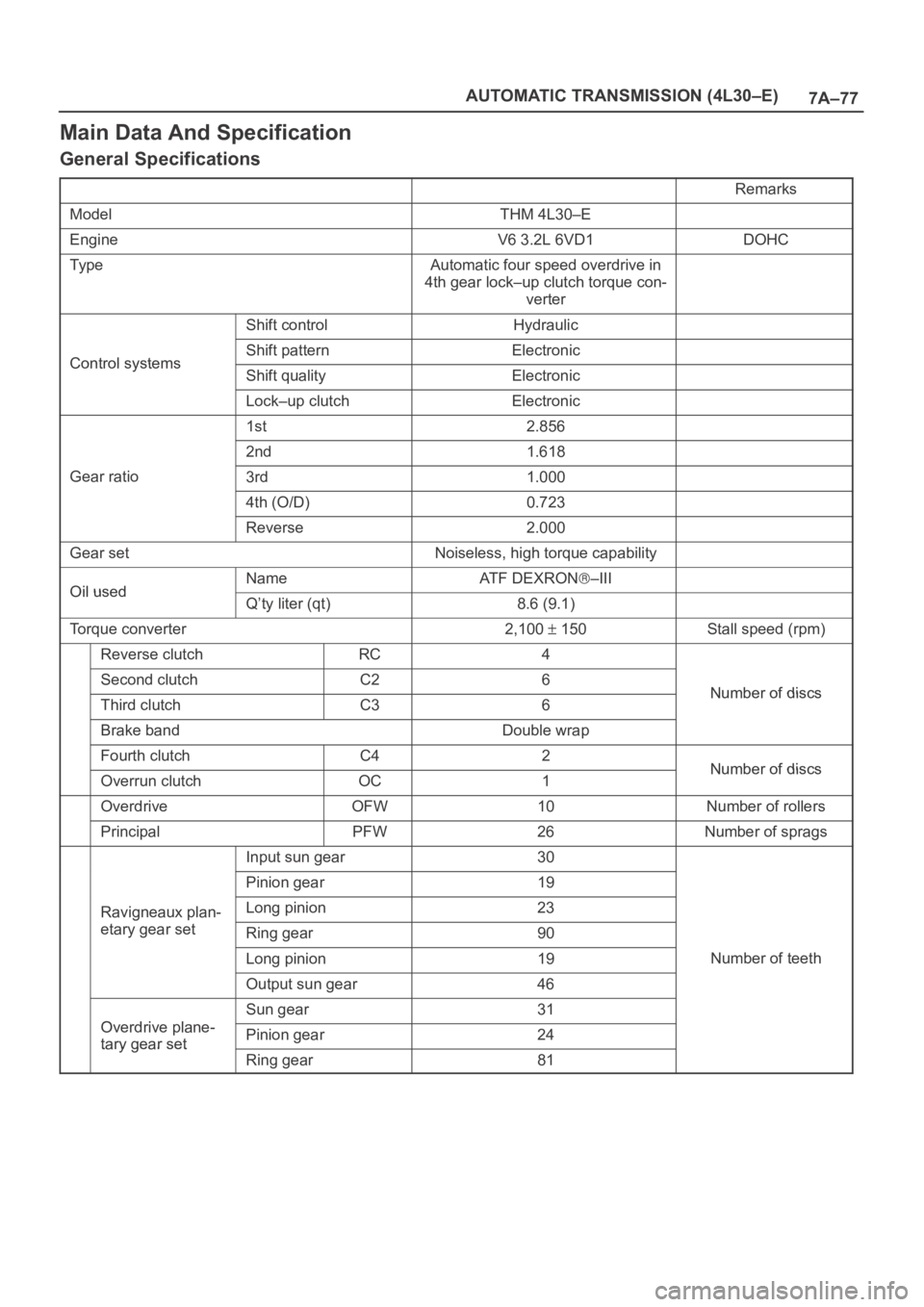
Main Data And Specification
General Specifications
Remarks
ModelTHM 4L30–E
EngineV6 3.2L 6VD1DOHC
Ty p eAutomatic four speed overdrive in
4th gear lock–up clutch torque con-
verter
Shift controlHydraulic
Control systemsShift patternElectronicControl systemsShift qualityElectronic
Lock–up clutchElectronic
1st2.856
2nd1.618
Gear ratio3rd1.000
4th (O/D)0.723
Reverse2.000
Gear setNoiseless, high torque capability
Oil usedNameAT F D E X R O N–IIIOil usedQ’ty liter (qt)8.6 (9.1)
Torque converter2,100 150Stall speed (rpm)
Reverse clutchRC4
Second clutchC26Number of discsThird clutchC36Number of discs
Brake bandDouble wrap
Fourth clutchC42Number of discsOverrun clutchOC1Number of discs
OverdriveOFW10Number of rollers
PrincipalPFW26Number of sprags
Input sun gear30
Pinion gear19
Ravigneaux plan-Long pinion23g
etary gear setRing gear90
Long pinion19Number of teeth
Output sun gear46
Odi l
Sun gear31
Overdrive plane-
tary gear setPinion gear24tary gear set
Ring gear81
Page 2239 of 6000
7A–85 AUTOMATIC TRANSMISSION (4L30–E)
(38) Seal, O–Ring
(39) Reservoir
(42) Gasket, Extension Case
(43) Extension Assembly
(44) Seal, O–Ring/Speed Sensor
(45) Sensor Assembly, Speed
(46) Screw, Speed Sensor
(50) Seal, Extension Assembly
(52) Screw, Extension/Main Case
(53) Spring, Parking Pawl Lock
(54) Pawl, Parking Lock
(55) Connector, Electrical/Main Case
(56) Actuator Assembly, Parking Lock
(57) Nut, Parking Lock Lever
(58) Link, Manual Valve
(59) Pin, Spring
(60) Lever, Parking Lock and Range Selector
(61) Shaft, Selector
(62) Seal, Selector Shaft
(63) Mode Switch Assembly
(64) Screw and Conical Washer Assembly
(65) Shield, Mode Switch
(67) Pan, Bottom/Adapter Case
(68) Gasket, Bottom Pan/Adapter Case
(69) Harness Assembly, Adapter Case
(70) Screw, Valve Body
(71) Valve Body Assembly, Adapter Case
(72) Gasket, Adapter Valve Body
(73) Plate, Adapter Valve Body/Transfer
(74) Pan, Bottom/Main Case(75) Gasket, Bottom Pan/Main Case
(76) Gasket, Oil Drain or Overfill Screw
(77) Screw, Oil Drain or Overfill
(78) Magnet, Chip Collector
(79) Filter Oil
(80) Harness Assembly, Main Case
(82) Roller and Spring Assembly, Manual Detent
(84) Valve Body Assembly, Main Case
(85) Ball, Check
(86) Gasket, Main V.B./Transfer Plate
(87) Plate, Main V.B./Transfer
(88) Gasket, Transfer/Main Case
(89) Screw, Transfer Plate on V.B.
(90) Screw, Servo Cover
(91) Cover, Servo Piston
(92) Gasket, Cover/Servo Piston
(93) Ring, Retaining Servo Piston
(94) Clip, Servo Piston
(95) Nut, Servo Screw
(96) Screw, Servo Piston
(97) Piston, Servo
(98) Seal, Ring/Servo Piston
(99) Spring, Cushion/Servo Piston
(100) Seat, Cushion Spring
(101) Sleeve, Servo Piston Adjust
(102) Rod, Apply/Servo Piston
(103) Spring, Return/Servo Piston
(104) Gasket, Adapter Case/Transfer Plate
(105) Powertrain Control Module
(106) Servo Piston Assembly
Page 2245 of 6000
7A–91 AUTOMATIC TRANSMISSION (4L30–E)
(646) Gear Assembly, Input Sun
(647) Race Assembly, Sprag
(648) Ring, Retaining/Sprag
(649) Ring, Retaining
(650) Cage Assembly, Sprag
(651) Bearing, Output Shaft/Input Sun
(652) Washer, Output Shaft/Input Sun
(653) Carrier Assembly, Planetary(658) Gear, Reaction Sun
(659) Drum, Reaction Sun
(664) Band Assembly, Brake
(667) Seal, Ring/Wheel Parking Lock
(668) Wheel, Parking Lock
(672) Wheel, Speed
(673) Ring, Retaining
(675) Bearing, Thrust Assembly
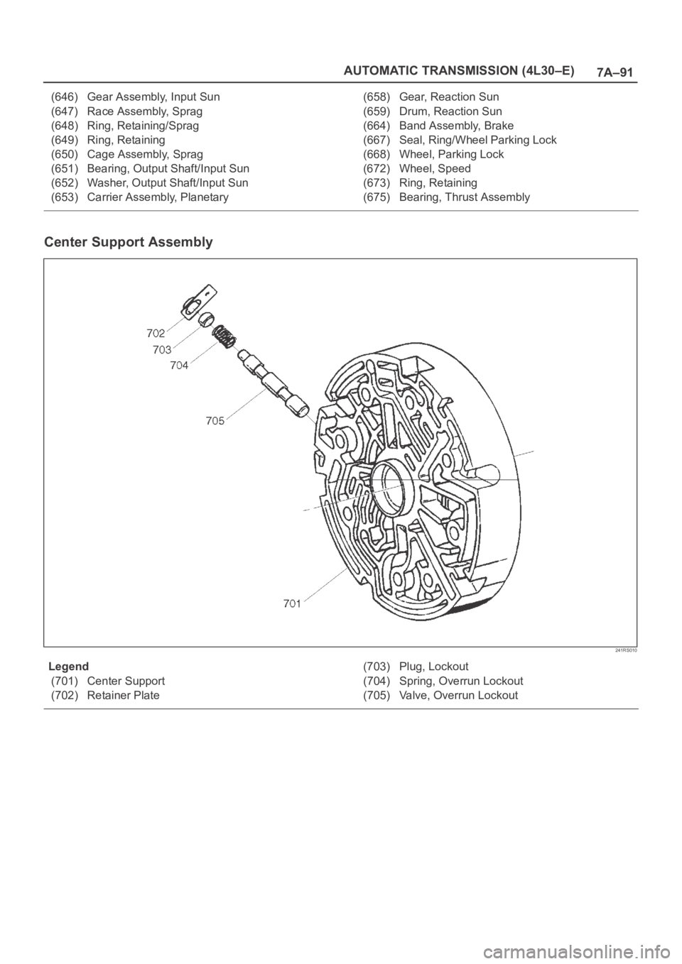
Center Support Assembly
241RS010
Legend
(701) Center Support
(702) Retainer Plate(703) Plug, Lockout
(704) Spring, Overrun Lockout
(705) Valve, Overrun Lockout
Page 2247 of 6000
7A1–2
TRANSMISSION CONTROL SYSTEM (4L30–E)
Service Precaution
WARNING: IF SO EQUIPPED WITH A
SUPPLEMENTAL RESTRAINT SYSTEM (SRS),
REFER TO THE SRS COMPONENT AND WIRING
LOCATION VIEW IN ORDER TO DETERMINE
WHETHER YOU ARE PERFORMING SERVICE ON OR
NEAR THE SRS COMPONENTS OR THE SRS
WIRING. WHEN YOU ARE PERFORMING SERVICE
ON OR NEAR THE SRS COMPONENTS OR THE SRS
WIRING, REFER TO THE SRS SERVICE
INFORMATION. FAILURE TO FOLLOW WARNINGS
COULD RESULT IN POSSIBLE AIR BAG
DEPLOYMENT, PERSONAL INJURY, OR
OTHERWISE UNNEEDED SRS SYSTEM REPAIRS.
CAUTION: Always use the correct fastener in the
proper location. When you replace a fastener, use
ONLY the exact part number for that application.
ISUZU will call out those fasteners that require a
replacement after removal. ISUZU will also call out
the fasteners that require thread lockers or thread
sealant. UNLESS OTHERWISE SPECIFIED, do not
use supplemental coatings (Paints, greases, or other
corrosion inhibitors) on threaded fasteners or
fastener joint interfaces. Generally, such coatings
adversely affect the fastener torque and the joint
clamping force, and may damage the fastener. When
you install fasteners, use the correct tightening
sequence and specifications. Following these
instructions can help you avoid damage to parts and
systems.
General Description
The 4L30–E is a 4–speed fully automatic transmission. It
uses a microcomputer as a control unit to judge running
conditions including throttle opening rate and vehicle
speed, then it sets the shifting point in the optimum timing
so that best driving performance can be achieved.
In addition, the built–in shift mode select function can
select three shift modes according to the driver’s
preference:
Normal mode –Normal shift pattern.
Winter mode –Starts in 3rd gear to reduce slippage on
ice or snow.
Power mode has a delayed upshift for when more
powerful acceleration is required.
Also, the built–in fail safe function (“backup mode”)
assures driving performance even if the vehicle speed
sensor, throttle signal or any solenoid fails.
Further, the self–diagnostic function conducts diagnosis
in a short time when the control system fails, thus
improving serviceability.
The major features of 4L30–E are as follows:
A compact structure consisting of 2 sets of planetary
gears and flat torque converter.
Electronic control selects the optimum shift mode
according to the driving conditions.
Electronic control maintains the optimum hydraulic
pressure for clutch, band brake as well as
transmission so that shift feeling is improved.
Two sets of planetary gears reduce friction of power
train.
Also, a lockup mechanism in the torque converter
reduces fuel consumption.
Wide gear ratio and high torque rate of torque
converter provide excellent starting performance.
Page 2316 of 6000
TRANSMISSION CONTROL SYSTEM (4L30–E)7A1–71
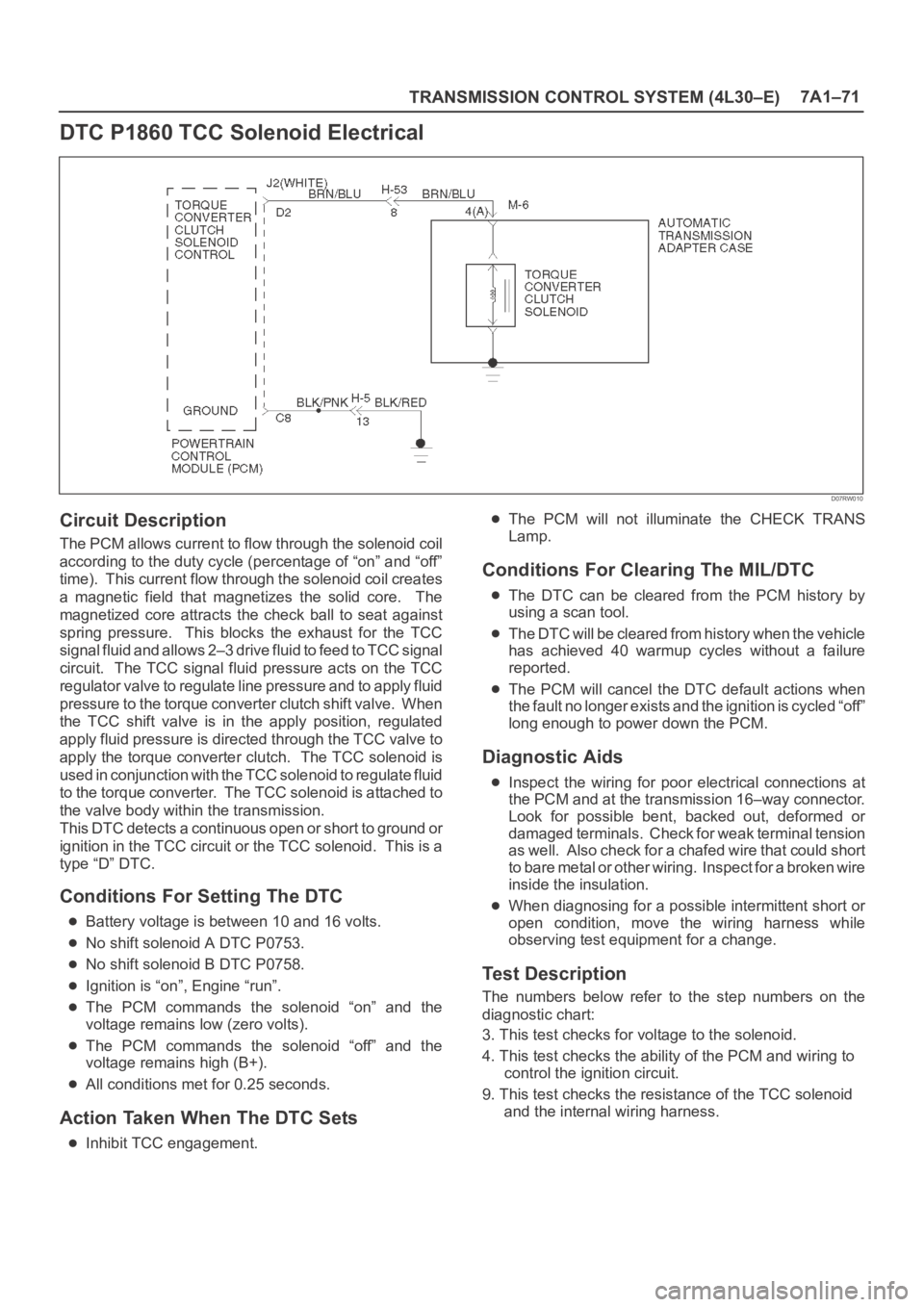
DTC P1860 TCC Solenoid Electrical
D07RW010
Circuit Description
The PCM allows current to flow through the solenoid coil
according to the duty cycle (percentage of “on” and “off”
time). This current flow through the solenoid coil creates
a magnetic field that magnetizes the solid core. The
magnetized core attracts the check ball to seat against
spring pressure. This blocks the exhaust for the TCC
signal fluid and allows 2–3 drive fluid to feed to TCC signal
circuit. The TCC signal fluid pressure acts on the TCC
regulator valve to regulate line pressure and to apply fluid
pressure to the torque converter clutch shift valve. When
the TCC shift valve is in the apply position, regulated
apply fluid pressure is directed through the TCC valve to
apply the torque converter clutch. The TCC solenoid is
used in conjunction with the TCC solenoid to regulate fluid
to the torque converter. The TCC solenoid is attached to
the valve body within the transmission.
This DTC detects a continuous open or short to ground or
ignition in the TCC circuit or the TCC solenoid. This is a
type “D” DTC.
Conditions For Setting The DTC
Battery voltage is between 10 and 16 volts.
No shift solenoid A DTC P0753.
No shift solenoid B DTC P0758.
Ignition is “on”, Engine “run”.
The PCM commands the solenoid “on” and the
voltage remains low (zero volts).
The PCM commands the solenoid “off” and the
voltage remains high (B+).
All conditions met for 0.25 seconds.
Action Taken When The DTC Sets
Inhibit TCC engagement.
The PCM will not illuminate the CHECK TRANS
Lamp.
Conditions For Clearing The MIL/DTC
The DTC can be cleared from the PCM history by
using a scan tool.
The DTC will be cleared from history when the vehicle
has achieved 40 warmup cycles without a failure
reported.
The PCM will cancel the DTC default actions when
the fault no longer exists and the ignition is cycled “off”
long enough to power down the PCM.
Diagnostic Aids
Inspect the wiring for poor electrical connections at
the PCM and at the transmission 16–way connector.
Look for possible bent, backed out, deformed or
damaged terminals. Check for weak terminal tension
as we ll. A lso ch eck fo r a ch af e d w ire th at cou l d s ho r t
to bare metal or other wiring. Inspect for a broken wire
inside the insulation.
When diagnosing for a possible intermittent short or
open condition, move the wiring harness while
observing test equipment for a change.
Test Description
The numbers below refer to the step numbers on the
diagnostic chart:
3. This test checks for voltage to the solenoid.
4. This test checks the ability of the PCM and wiring to
control the ignition circuit.
9. This test checks the resistance of the TCC solenoid
and the internal wiring harness.
Page 2319 of 6000
MANUAL TRANSMISSION7B–1
TRANSMISSION
MANUAL TRANSMISSION
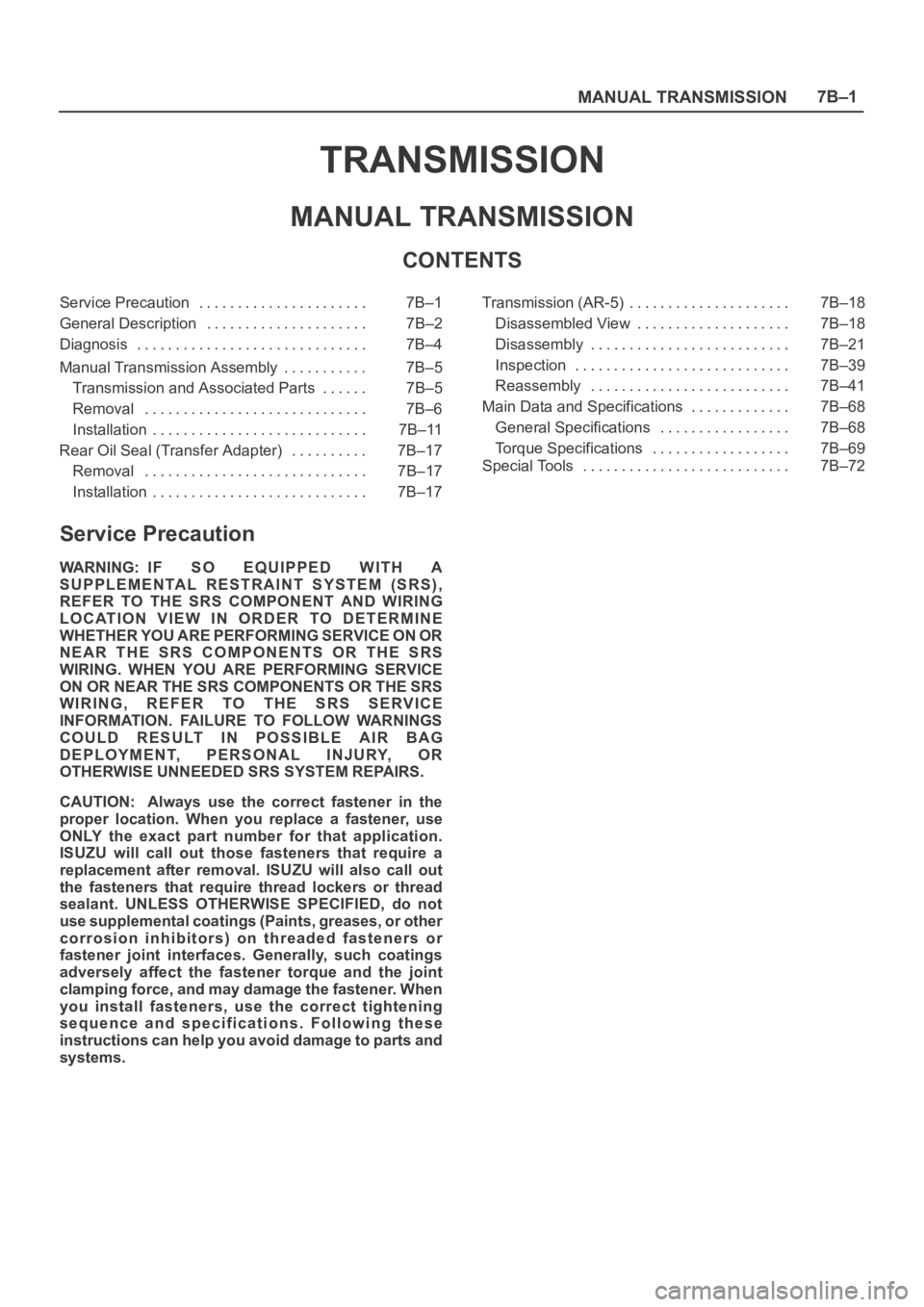
CONTENTS
Service Precaution 7B–1. . . . . . . . . . . . . . . . . . . . . .
General Description 7B–2. . . . . . . . . . . . . . . . . . . . .
Diagnosis 7B–4. . . . . . . . . . . . . . . . . . . . . . . . . . . . . .
Manual Transmission Assembly 7B–5. . . . . . . . . . .
Transmission and Associated Parts 7B–5. . . . . .
Removal 7B–6. . . . . . . . . . . . . . . . . . . . . . . . . . . . .
Installation 7B–11. . . . . . . . . . . . . . . . . . . . . . . . . . . .
Rear Oil Seal (Transfer Adapter) 7B–17. . . . . . . . . .
Removal 7B–17. . . . . . . . . . . . . . . . . . . . . . . . . . . . .
Installation 7B–17. . . . . . . . . . . . . . . . . . . . . . . . . . . . Transmission (AR-5) 7B–18. . . . . . . . . . . . . . . . . . . . .
Disassembled View 7B–18. . . . . . . . . . . . . . . . . . . .
Disassembly 7B–21. . . . . . . . . . . . . . . . . . . . . . . . . .
Inspection 7B–39. . . . . . . . . . . . . . . . . . . . . . . . . . . .
Reassembly 7B–41. . . . . . . . . . . . . . . . . . . . . . . . . .
Main Data and Specifications 7B–68. . . . . . . . . . . . .
General Specifications 7B–68. . . . . . . . . . . . . . . . .
Torque Specifications 7B–69. . . . . . . . . . . . . . . . . .
Special Tools 7B–72. . . . . . . . . . . . . . . . . . . . . . . . . . .
Service Precaution
WARNING: IF SO EQUIPPED WITH A
SUPPLEMENTAL RESTRAINT SYSTEM (SRS),
REFER TO THE SRS COMPONENT AND WIRING
LOCATION VIEW IN ORDER TO DETERMINE
WHETHER YOU ARE PERFORMING SERVICE ON OR
NEAR THE SRS COMPONENTS OR THE SRS
WIRING. WHEN YOU ARE PERFORMING SERVICE
ON OR NEAR THE SRS COMPONENTS OR THE SRS
WIRING, REFER TO THE SRS SERVICE
INFORMATION. FAILURE TO FOLLOW WARNINGS
COULD RESULT IN POSSIBLE AIR BAG
DEPLOYMENT, PERSONAL INJURY, OR
OTHERWISE UNNEEDED SRS SYSTEM REPAIRS.
CAUTION: Always use the correct fastener in the
proper location. When you replace a fastener, use
ONLY the exact part number for that application.
ISUZU will call out those fasteners that require a
replacement after removal. ISUZU will also call out
the fasteners that require thread lockers or thread
sealant. UNLESS OTHERWISE SPECIFIED, do not
use supplemental coatings (Paints, greases, or other
corrosion inhibitors) on threaded fasteners or
fastener joint interfaces. Generally, such coatings
adversely affect the fastener torque and the joint
clamping force, and may damage the fastener. When
you install fasteners, use the correct tightening
sequence and specifications. Following these
instructions can help you avoid damage to parts and
systems.
Page 2322 of 6000
7B–4MANUAL TRANSMISSION
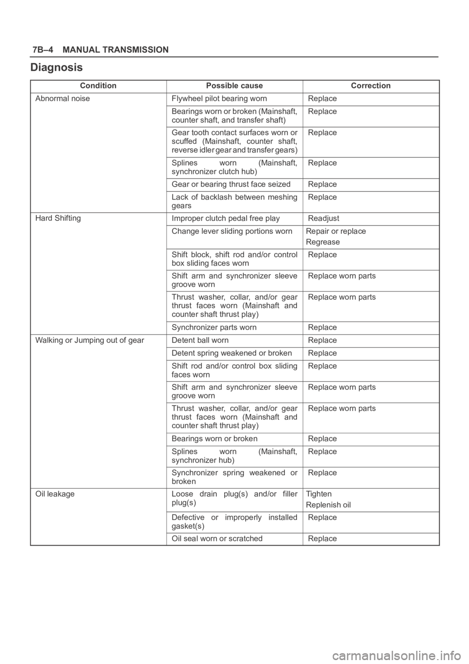
Diagnosis
ConditionPossible causeCorrection
Abnormal noiseFlywheel pilot bearing wornReplace
Bearings worn or broken (Mainshaft,
counter shaft, and transfer shaft)Replace
Gear tooth contact surfaces worn or
scuffed (Mainshaft, counter shaft,
reverse idler gear and transfer gears)Replace
Splines worn (Mainshaft,
synchronizer clutch hub)Replace
Gear or bearing thrust face seizedReplace
Lack of backlash between meshing
gearsReplace
Hard ShiftingImproper clutch pedal free playReadjust
Change lever sliding portions wornRepair or replace
Regrease
Shift block, shift rod and/or control
box sliding faces wornReplace
Shift arm and synchronizer sleeve
groove wornReplace worn parts
Thrust washer, collar, and/or gear
thrust faces worn (Mainshaft and
counter shaft thrust play)Replace worn parts
Synchronizer parts wornReplace
Walking or Jumping out of gearDetent ball wornReplace
Detent spring weakened or brokenReplace
Shift rod and/or control box sliding
faces wornReplace
Shift arm and synchronizer sleeve
groove wornReplace worn parts
Thrust washer, collar, and/or gear
thrust faces worn (Mainshaft and
counter shaft thrust play)Replace worn parts
Bearings worn or brokenReplace
Splines worn (Mainshaft,
synchronizer hub)Replace
Synchronizer spring weakened or
brokenReplace
Oil leakageLoose drain plug(s) and/or filler
plug(s)Tighten
Replenish oil
Defective or improperly installed
gasket(s)Replace
Oil seal worn or scratchedReplace