1998 OPEL FRONTERA oil type
[x] Cancel search: oil typePage 959 of 6000
6A–3
ENGINE MECHANICAL
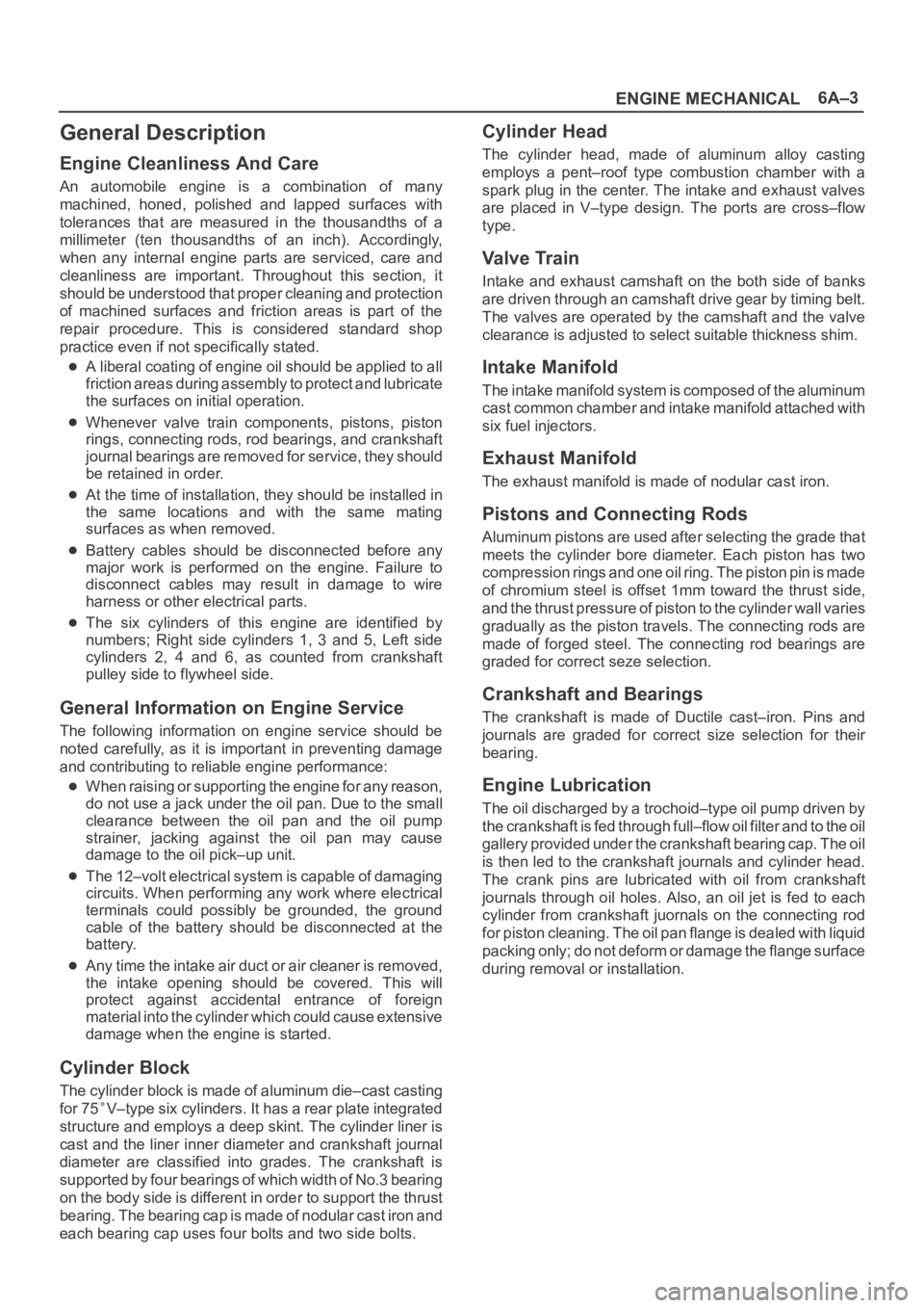
General Description
Engine Cleanliness And Care
An automobile engine is a combination of many
machined, honed, polished and lapped surfaces with
tolerances that are measured in the thousandths of a
millimeter (ten thousandths of an inch). Accordingly,
when any internal engine parts are serviced, care and
cleanliness are important. Throughout this section, it
should be understood that proper cleaning and protection
of machined surfaces and friction areas is part of the
repair procedure. This is considered standard shop
practice even if not specifically stated.
A liberal coating of engine oil should be applied to all
friction areas during assembly to protect and lubricate
the surfaces on initial operation.
Whenever valve train components, pistons, piston
rings, connecting rods, rod bearings, and crankshaft
journal bearings are removed for service, they should
be retained in order.
At the time of installation, they should be installed in
the same locations and with the same mating
surfaces as when removed.
Battery cables should be disconnected before any
major work is performed on the engine. Failure to
disconnect cables may result in damage to wire
harness or other electrical parts.
The six cylinders of this engine are identified by
numbers; Right side cylinders 1, 3 and 5, Left side
cylinders 2, 4 and 6, as counted from crankshaft
pulley side to flywheel side.
General Information on Engine Service
The following information on engine service should be
noted carefully, as it is important in preventing damage
and contributing to reliable engine performance:
When raising or supporting the engine for any reason,
do not use a jack under the oil pan. Due to the small
clearance between the oil pan and the oil pump
strainer, jacking against the oil pan may cause
damage to the oil pick–up unit.
The 12–volt electrical system is capable of damaging
circuits. When performing any work where electrical
terminals could possibly be grounded, the ground
cable of the battery should be disconnected at the
battery.
Any time the intake air duct or air cleaner is removed,
the intake opening should be covered. This will
protect against accidental entrance of foreign
material into the cylinder which could cause extensive
damage when the engine is started.
Cylinder Block
The cylinder block is made of aluminum die–cast casting
for 75
V–type six cylinders. It has a rear plate integrated
structure and employs a deep skint. The cylinder liner is
cast and the liner inner diameter and crankshaft journal
diameter are classified into grades. The crankshaft is
supported by four bearings of which width of No.3 bearing
on the body side is different in order to support the thrust
bearing. The bearing cap is made of nodular cast iron and
each bearing cap uses four bolts and two side bolts.
Cylinder Head
The cylinder head, made of aluminum alloy casting
employs a pent–roof type combustion chamber with a
spark plug in the center. The intake and exhaust valves
are placed in V–type design. The ports are cross–flow
type.
Va l v e Tr a i n
Intake and exhaust camshaft on the both side of banks
are driven through an camshaft drive gear by timing belt.
The valves are operated by the camshaft and the valve
clearance is adjusted to select suitable thickness shim.
Intake Manifold
The intake manifold system is composed of the aluminum
cast common chamber and intake manifold attached with
six fuel injectors.
Exhaust Manifold
The exhaust manifold is made of nodular cast iron.
Pistons and Connecting Rods
Aluminum pistons are used after selecting the grade that
meets the cylinder bore diameter. Each piston has two
compression rings and one oil ring. The piston pin is made
of chromium steel is offset 1mm toward the thrust side,
and the thrust pressure of piston to the cylinder wall varies
gradually as the piston travels. The connecting rods are
made of forged steel. The connecting rod bearings are
graded for correct seze selection.
Crankshaft and Bearings
The crankshaft is made of Ductile cast–iron. Pins and
journals are graded for correct size selection for their
bearing.
Engine Lubrication
The oil discharged by a trochoid–type oil pump driven by
the crankshaft is fed through full–flow oil filter and to the oil
gallery provided under the crankshaft bearing cap. The oil
is then led to the crankshaft journals and cylinder head.
The crank pins are lubricated with oil from crankshaft
journals through oil holes. Also, an oil jet is fed to each
cylinder from crankshaft juornals on the connecting rod
for piston cleaning. The oil pan flange is dealed with liquid
packing only; do not deform or damage the flange surface
during removal or installation.
Page 963 of 6000
6A–7
ENGINE MECHANICAL
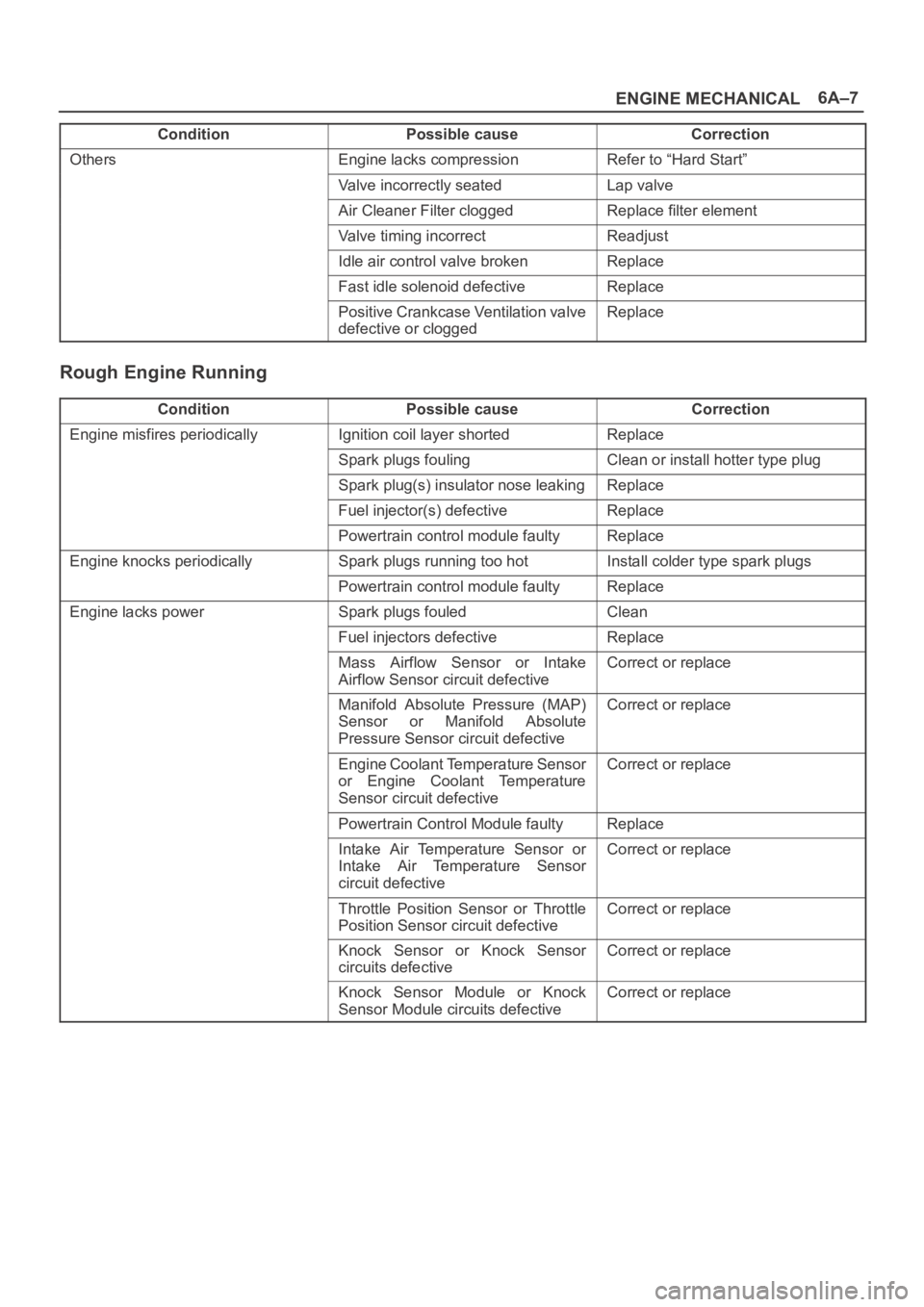
Condition CorrectionPossible cause
OthersEngine lacks compressionRefer to “Hard Start”
Valve incorrectly seatedLap valve
Air Cleaner Filter cloggedReplace filter element
Valve timing incorrectReadjust
Idle air control valve brokenReplace
Fast idle solenoid defectiveReplace
Positive Crankcase Ventilation valve
defective or cloggedReplace
Rough Engine Running
ConditionPossible causeCorrection
Engine misfires periodicallyIgnition coil layer shortedReplace
Spark plugs foulingClean or install hotter type plug
Spark plug(s) insulator nose leakingReplace
Fuel injector(s) defectiveReplace
Powertrain control module faultyReplace
Engine knocks periodicallySpark plugs running too hotInstall colder type spark plugs
Powertrain control module faultyReplace
Engine lacks powerSpark plugs fouledClean
Fuel injectors defectiveReplace
Mass Airflow Sensor or Intake
Airflow Sensor circuit defectiveCorrect or replace
Manifold Absolute Pressure (MAP)
Sensor or Manifold Absolute
Pressure Sensor circuit defectiveCorrect or replace
Engine Coolant Temperature Sensor
or Engine Coolant Temperature
Sensor circuit defectiveCorrect or replace
Powertrain Control Module faultyReplace
Intake Air Temperature Sensor or
Intake Air Temperature Sensor
circuit defectiveCorrect or replace
Throttle Position Sensor or Throttle
Position Sensor circuit defectiveCorrect or replace
Knock Sensor or Knock Sensor
circuits defectiveCorrect or replace
Knock Sensor Module or Knock
Sensor Module circuits defectiveCorrect or replace
Page 1046 of 6000
6A–90
ENGINE MECHANICAL
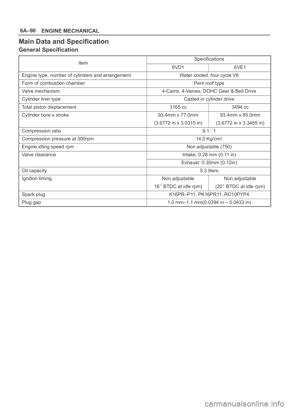
Main Data and Specification
General Specification
ItemSpecificationsItem6VD16VE1
Engine type, number of cylinders and arrangementWater cooled, four cycle V6
Form of combustion chamberPent roof type
Valve mechanism4-Cams, 4-Valves, DOHC Gear & Belt Drive
Cylinder liner typeCasted in cylinder drive
Total piston displacement3165 cc3494 cc
Cylinder bore x stroke93.4mm x 77.0mm93.4mm x 85.0mm
(3.6772 in x 3.0315 in)(3.6772 in x 3.3465 in)
Compression ratio9.1 : 1
Compression pressure at 300rpm14.0 Kg/cm
Engine idling speed rpmNon adjustable (750)
Valve clearanceIntake: 0.28 mm (0.11 in)
Exhaust: 0.30mm (0.12in)
Oil capacity5.3 liters
Ignition timingNon adjustableNon adjustable
16 BTDC at idle rpm)(20 BTDC at idle rpm)
Spark plugK16PR–P11, PK16PR11, RC10PYP4
Plug gap1.0 mm–1.1 mm(0.0394 in – 0.0433 in)
Page 1056 of 6000
ENGINE COOLING6B–3
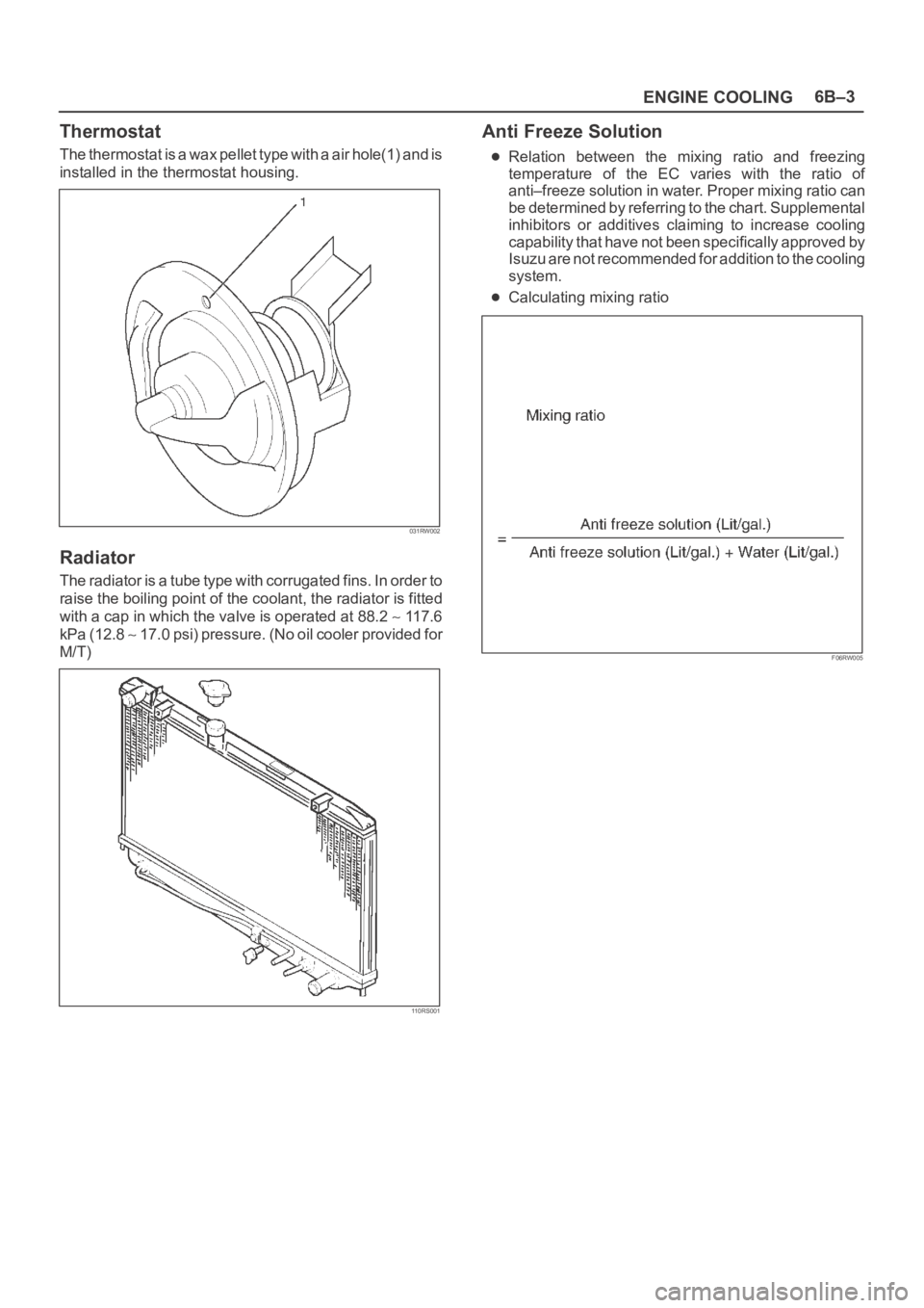
Thermostat
The thermostat is a wax pellet type with a air hole(1) and is
installed in the thermostat housing.
031RW002
Radiator
The radiator is a tube type with corrugated fins. In order to
raise the boiling point of the coolant, the radiator is fitted
with a cap in which the valve is operated at 88.2
117.6
kPa (12.8
1 7 . 0 p s i ) p r e s s u r e . ( N o o i l c o o l e r p r o v i d e d f o r
M/T)
110RS001
Anti Freeze Solution
Relation between the mixing ratio and freezing
temperature of the EC varies with the ratio of
anti–freeze solution in water. Proper mixing ratio can
be determined by referring to the chart. Supplemental
inhibitors or additives claiming to increase cooling
capability that have not been specifically approved by
Isuzu are not recommended for addition to the cooling
system.
Calculating mixing ratio
F06RW005
Page 1089 of 6000
6D2–4
IGNITION SYSTEM
Spark Plug
Removal
1. Remove spark plugs.
Inspection and Repair
The spark plug affects entire engine performance and
therefore its inspection is very important.
Check electrode and insulator for presence of cracks,
and replace if any.
Check electrode for wear, and replace if necessary.
Check gasket for damage, and replace if necessary.
Measure insulation resistance with an ohmmeter, and
replace if faulty.
Adjust spark plug gap to 1.0 mm (0.04 in) 1.1 mm
(0.043 in).
Check fuel and electrical systems if spark plug is
extremely dirty.
Use spark plugs having low heat value (hot type plug)
if fuel and electrical systems are normal.
Use spark plugs having high heat value (cold type
plug) if insulator and electrode are extremely burned.
Sooty Spark Plugs
Much deposit of carbon or oil on the electrode and
insulator of spark plug reduces the engine performance.
Possible causes:
Too rich mixture
Presence of oil in combustion chamber
Incorrectly adjusted spark plug gap
Burning Electrodes
This fault is characterized by scorched or heavily oxidized
electrode or blistered insulator nose.
Possible causes:
Too lean mixture
Improper heat value
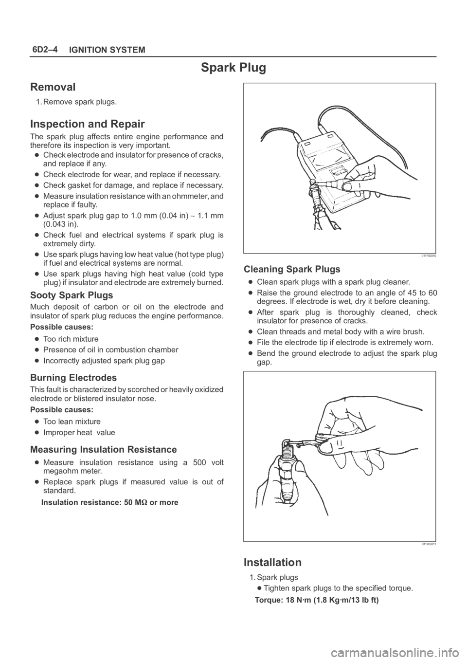
Measuring Insulation Resistance
Measure insulation resistance using a 500 volt
megaohm meter.
Replace spark plugs if measured value is out of
standard.
Insulation resistance: 50 M
or more
011RS010
Cleaning Spark Plugs
Clean spark plugs with a spark plug cleaner.
Raise the ground electrode to an angle of 45 to 60
degrees. If electrode is wet, dry it before cleaning.
After spark plug is thoroughly cleaned, check
insulator for presence of cracks.
Clean threads and metal body with a wire brush.
File the electrode tip if electrode is extremely worn.
Bend the ground electrode to adjust the spark plug
gap.
011RS011
Installation
1. Spark plugs
Tighten spark plugs to the specified torque.
Torque: 18 Nꞏm (1.8 Kgꞏm/13 lb ft)
Page 1109 of 6000
6D3–18STARTING AND CHARGING SYSTEM
Charging System
General Description
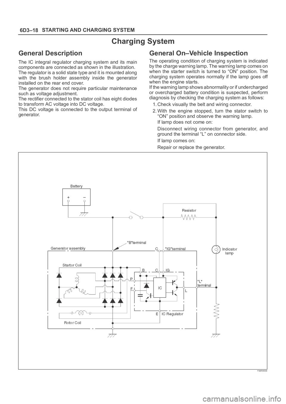
The IC integral regulator charging system and its main
components are connected as shown in the illustration.
The regulator is a solid state type and it is mounted along
with the brush holder assembly inside the generator
installed on the rear end cover.
The generator does not require particular maintenance
such as voltage adjustment.
The rectifier connected to the stator coil has eight diodes
to transform AC voltage into DC voltage.
This DC voltage is connected to the output terminal of
generator.
General On–Vehicle Inspection
The operating condition of charging system is indicated
by the charge warning lamp. The warning lamp comes on
when the starter switch is turned to “ON” position. The
charging system operates normally if the lamp goes off
when the engine starts.
If the warning lamp shows abnormality or if undercharged
or overcharged battery condition is suspected, perform
diagnosis by checking the charging system as follows:
1. Check visually the belt and wiring connector.
2. With the engine stopped, turn the stator switch to
“ON” position and observe the warning lamp.
If lamp does not come on:
Disconnect wiring connector from generator, and
ground the terminal “L” on connector side.
If lamp comes on:
Repair or replace the generator.
F06RW009
Page 1197 of 6000
6E–80
ENGINE DRIVEABILITY AND EMISSIONS
Circuit Description
The electronic Ignition system uses a coil-at-plug method
of spark distribution. In this type of ignition system, the
powertrain control module (PCM) triggers the correct
driver inside the ignition coil, which then triggers the
correct ignition coil based on the 58X signal received from
the crankshaft position sensor (CKP). The spark plug
connected to the coil fires when the ICM opens the ground
circuit for the coil’s primary circuit.
During crank, the PCM monitors the CKP 58X signal. The
CKP signal is used to determine which cylinder will fire
first. After the CKP 58X signal has been processed by the
PCM, it will command all six injectors to allow a priming
shot of fuel for all the cylinders. After the priming, the
injectors are left “OFF” during the next six 58X reference
pulses from the CKP. This allows each cylinder a chance
to use the fuel from the priming shot. During this waiting
period, a camshaft position (CMP) signal pulse will have
been received by the PCM. The CMP signal allows the
PCM to operate the injectors sequentially based on
camshaft position. If the camshaft position signal is not
present at start-up, the PCM will begin sequential fuel
delivery with a 1-in-6 chance that fuel delivery is correct.
The engine will run without a CMP signal, but will set a
DTC code.
Diagnostic Aids
An intermittent problem may be caused by a poor
connection, rubbed-through wire insulation or a wire
broken inside the insulation. Check for the following
items:
Poor connection or damaged harness – Inspect the
PCM harness and connectors for improper mating,
broken locks, improperly formed or damaged
terminals, poor terminal-to-wire connection, and
damaged harness.
Faulty engine coolant temperature sensor – Using
Tech 2, compare engine coolant temperature with
intake air temperature on a completely cool engine.
Engine coolant temperature should be within 10
C of
intake air temperature. If not, replace the ECT sensor.
Test Description
Number(s) below refer to the step number(s) on the
Diagnostic Chart.
5. An obvious cause of low fuel pressure would be an
empty fuel tank.
6. The engine will easily start and run if a few injectors
are disabled. It is not necessary to test all injectors
at this time since this step is only a test to verify that
all of the injectors have not been disabled by fuel
contamination.
7. A blinking test light verifies that the PCM is
monitoring the 58X crankshaft reference signal and
is capable of activating the injectors. If there is an
open or shorted driver circuit, DTCs 201-206 should
be set.
19.By using a spark tester, each ignition coil’s ability to
produce 25,000 volts is verified.
25.If there is an open or shorted driver circuit, DTCs
201-206 should be set. All six injector driver circuits
can be checked at one time without removing the
intake manifold if a 5-8840-2636-0 test light is
available. This is the alternative procedure:
With the ignition “OFF,” disconnect the gray
connector located at the rear of the air filter, attached
to a bracket on the purge canister.
Connect test light 5-8840-2636-0 to the connector.
Do any of the light constantly illuminate or fail to blink
when the engine is cranked? If so, repair the short or
open circuit, or replace the PCM if indicated.
This procedure only tests the driver circuit as far as the
test connection, so step 31 is added to test the circuit all
the way to the injector.
Page 1379 of 6000
6E–262
ENGINE DRIVEABILITY AND EMISSIONS
Symptom Diagnosis
Preliminary Checks
Before using this section, perform the “On-Board
Diagnostic (OBD) System Check” and verify all of the
following items:
The powertrain control module (PCM) and malfunction
indicator lamp (MIL) (Service Engine Soon lamp) are
operating correctly.
There are no DTC(s) stored.
Tech 2 data is within normal operating range. Refer to
Typical Scan Data Values.
Verify the customer complaint and locate the correct
symptom in the table of contents. Perform the
procedure included in the symptom chart.
Visual/Physical Check
Several of the symptom procedures call for a careful
visual/physical check. This can lead to correcting a
problem without further checks and can save valuable
time.
This check should include the following items:
PCM grounds for cleanliness, tightness and proper
location.
Vacuum hoses for splits, kinks, and proper
connections, as shown on the “Vehicle Emission
Control Information” label. Check thoroughly for any
type of leak or restriction.
Air intake ducts for collapsed or damaged areas.
Air leaks at throttle body mounting area, mass air flow
(MAF) sensor and intake manifold sealing surfaces.
Ignition wires for cracking, hardness, and carbon
tracking.
Wiring for proper connections, pinches and cuts.
Intermittents
IMPORTANT:An intermittent problem may or may not
turn on the malfunction indicator lamp (MIL) or store a
DTC. DO NOT use the Diagnostic Trouble Code (DTC)
charts for intermittent problems. The fault must be
present to locate the problem.
Most intermittent problems are caused by faulty electrical
connections or wiring. Perform a careful visual/physical
check for the following conditions:
Poor mating of the connector halves or a terminal not
fully seated in the connector (backed out).
Improperly formed or damaged terminal.
All connector terminals in the problem circuit should be
carefully checked for proper contact tension.
Poor terminal-to-wire connection. This requires
removing the terminal from the connector body to
check.
Road test the vehicle with a J 39200 Digital Multimeter
connected to a suspected circuit. An abnormal voltage
when the malfunction occurs is a good indication that
there is a fault in the circuit being monitored.
Use Tech 2 to help detect intermittent conditions. Tech 2s
have several features that can be used to locate anintermittent condition. Use the following feature to find
intermittent faults:
Using Tech 2’s “Freeze Frame” buffer or “Failure
Records” buffer can aid in locating an intermittent
condition. Review and record the information in the
freeze frame or failure record associated with the
intermittent DTC being diagnosed. The vehicle can be
driven within the conditions that were present when the
DTC originally set.
To check for loss of diagnostic code memory, disconnect
the MAP sensor and idle the engine until the MIL (Service
Engine Soon lamp) comes on. DTC P0107 should be
stored and kept in memory when the ignition is turned
“OFF.” If not, the PCM is faulty. When this test is
completed, make sure that you clear the DTC P0107 from
memory.
An intermittent MIL (Service Engine Soon lamp) with no
stored DTC may be caused by the following:
Ignition coil shorted to ground and arcing at ignition
wires or plugs.
MIL (Service Engine Soon lamp) wire to PCM shorted
to ground.
Poor PCM grounds. Refer to the PCM wiring
diagrams.
Check for improper installation of electrical options such
as lights, cellular phones, etc. Route ignition coil wiring
away from the ignition coils. Check all wires from the
PCM to the ignition coil for poor connections.
Check for an open diode across the A/C compressor
clutch and check for other open diodes (refer to wiring
diagrams in
Electrical Diagnosis).
If problem has not been found, refer to
PCM Connector
Symptom
tables.