Page 684 of 6000

4C–18
DRIVE SHAFT SYSTEM
17. Install oil seal by using installer 5–8840–2120–0 and
grip 5–8840–0007–0.
Apply grease (NLGI No.2 or equivalent) to the lip
portion.
411RW008
18. Install ABS sensor ring (if so equipped).
Tighten the bolts to the specified torque.
Torque:18Nꞏm (1.8kgꞏm/13lbft)
19. Install hub and disc assembly.
1. Apply grease in the hub.
2. Apply wheel bearing type grease NLGI No.2 or
equivalent to the outer and inner bearing.
Grease Amount
Hub: 35 g (1.23 oz)
Outer bearing: 10 g (0.35 oz)
Inner bearing: 15 g (0.53 oz)
20. Install hub nut.
1. Turn the place where there is a chamfer in the
tapped hole to the outer side, and attach the nut
by using wrench 5–8840–2117–0.
411RW005
Preload Adjustment
Tighten the hub nut to 29 Nꞏm (3.0 kgꞏm/22 lbꞏft),
then fully loosen the nut.
Tighten the hub nut to the value given below, using
a spring scale on the wheel pin.
Bearing Preload
New bearing and New oil seal:
20-25N (2-2.5 kg/4.4-5.5 lb)
Used bearing and New oil seal:
12-18N (1.2-1.8 kg/2.6-4.0 lb)
If the measured bearing preload is outside the
specifications, adjust it by loosening or tightening
the bearing nut.
411RS011
Page 701 of 6000
4C–35 DRIVE SHAFT SYSTEM
Main Data and Specifications
General Specifications
Front drive axle oil capacity1.4 liter (1.23 Imp qt/1.48 US qt)(Differential)
0.12 liter (0.10 Imp qt/0.13 US qt)(Actuator Housing:Shift on the fly)
Type of lubricantGL–5 (Multi grade type) Refer to chart in General Information
Axle shaft typeConstant velocity joint(Birfield joint type and double offset joint)
Torque Specifications
E04RW020
Page 722 of 6000

TRANSFER CASE (STANDARD TYPE)
4D1–1
DRIVELINE/AXLE
TRANSFER CASE (STANDARD TYPE)
CONTENTS
Service Precaution 4D1–1. . . . . . . . . . . . . . . . . . . . . .
General Description 4D1–2. . . . . . . . . . . . . . . . . . . . .
Transfer Rear Oil Seal 4D1–8. . . . . . . . . . . . . . . . . . .
Removal 4D1–8. . . . . . . . . . . . . . . . . . . . . . . . . . . . .
Installation 4D1–8. . . . . . . . . . . . . . . . . . . . . . . . . . . .
Transfer Case Assembly 4D1–9. . . . . . . . . . . . . . . . .
Removal 4D1–9. . . . . . . . . . . . . . . . . . . . . . . . . . . . .
Installation 4D1–10. . . . . . . . . . . . . . . . . . . . . . . . . . . .
Transfer Rear Cover Assembly
(4WD Switch Model) 4D1–11. . . . . . . . . . . . . . . . . . . .
Transfer Rear Cover Assembly and
Associated Parts 4D1–11. . . . . . . . . . . . . . . . . . . . . .
Removal 4D1–12. . . . . . . . . . . . . . . . . . . . . . . . . . . . .
Installation 4D1–13. . . . . . . . . . . . . . . . . . . . . . . . . . . .
Disassembly 4D1–16. . . . . . . . . . . . . . . . . . . . . . . . . .
Inspection and Repair 4D1–17. . . . . . . . . . . . . . . . . .
Reassembly 4D1–17. . . . . . . . . . . . . . . . . . . . . . . . . .
Transfer Rear Cover Assembly
(Except 4WD Switch Model) 4D1–19. . . . . . . . . . . . . . Transfer Rear Cover Assembly and
Associated Parts 4D1–19. . . . . . . . . . . . . . . . . . . . . .
Removal 4D1–20. . . . . . . . . . . . . . . . . . . . . . . . . . . . .
Installation 4D1–20. . . . . . . . . . . . . . . . . . . . . . . . . . . .
Disassembly 4D1–23. . . . . . . . . . . . . . . . . . . . . . . . . .
Inspection and Repair 4D1–24. . . . . . . . . . . . . . . . . .
Reassembly 4D1–24. . . . . . . . . . . . . . . . . . . . . . . . . .
Detent, Shift Arm, and Interlock Pin 4D1–26. . . . . . . .
Disassembled View 4D1–26. . . . . . . . . . . . . . . . . . . .
Disassembly 4D1–26. . . . . . . . . . . . . . . . . . . . . . . . . .
Inspection and Repair 4D1–28. . . . . . . . . . . . . . . . . .
Reassembly 4D1–28. . . . . . . . . . . . . . . . . . . . . . . . . .
Transfer Case Assembly 4D1–30. . . . . . . . . . . . . . . . .
Disassembled View 4D1–30. . . . . . . . . . . . . . . . . . . .
Disassembly 4D1–31. . . . . . . . . . . . . . . . . . . . . . . . . .
Inspection and Repair 4D1–33. . . . . . . . . . . . . . . . . .
Reassembly 4D1–37. . . . . . . . . . . . . . . . . . . . . . . . . .
Main Data and Specifications 4D1–43. . . . . . . . . . . . .
Special Tools 4D1–46. . . . . . . . . . . . . . . . . . . . . . . . . . .
Service Precaution
WARNING: THIS VEHICLE HAS A SUPPLEMENTAL
RESTRAINT SYSTEM (SRS). REFER TO THE SRS
COMPONENT AND WIRING LOCATION VIEW IN
ORDER TO DETERMINE WHETHER YOU ARE
PERFORMING SERVICE ON OR NEAR THE SRS
COMPONENTS OR THE SRS WIRING. WHEN YOU
ARE PERFORMING SERVICE ON OR NEAR THE SRS
COMPONENTS OR THE SRS WIRING, REFER TO
THE SRS SERVICE INFORMATION. FAILURE TO
FOLLOW WARNINGS COULD RESULT IN POSSIBLE
AIR BAG DEPLOYMENT, PERSONAL INJURY, OR
OTHERWISE UNNEEDED SRS SYSTEM REPAIRS.
CAUTION: Always use the correct fastener in the
proper location. When you replace a fastener, use
ONLY the exact part number for that application.
ISUZU will call out those fasteners that require a
replacement after removal. ISUZU will also call out
the fasteners that require thread lockers or thread
sealant. UNLESS OTHERWISE SPECIFIED, do not
use supplemental coatings (Paints, greases, or other
corrosion inhibitors) on threaded fasteners or
fastener joint interfaces. Generally, such coatings
adversely affect the fastener torque and the joint
clamping force, and may damage the fastener. When
you install fasteners, use the correct tightening
sequence and specifications. Following these
instructions can help you avoid damage to parts and
systems.
Page 729 of 6000

4D1–8
TRANSFER CASE (STANDARD TYPE)
Transfer Rear Oil Seal
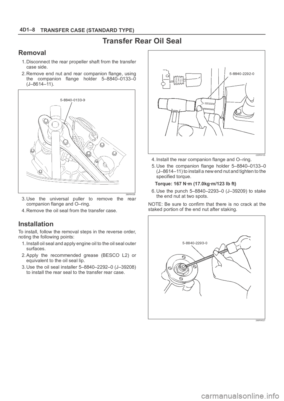
Removal
1. Disconnect the rear propeller shaft from the transfer
case side.
2. Remove end nut and rear companion flange, using
the companion flange holder 5–8840–0133–0
(J–8614–11).
266RW026
3. Use the universal puller to remove the rear
companion flange and O–ring.
4. Remove the oil seal from the transfer case.
Installation
To install, follow the removal steps in the reverse order,
noting the following points:
1. Install oil seal and apply engine oil to the oil seal outer
surfaces.
2. Apply the recommended grease (BESCO L2) or
equivalent to the oil seal lip.
3. Use the oil seal installer 5–8840–2292–0 (J–39208)
to install the rear seal to the transfer rear case.
220RW105
4. Install the rear companion flange and O–ring.
5. Use the companion flange holder 5–8840–0133–0
(J–8614–11) to install a new end nut and tighten to the
specified torque.
Torque: 167 Nꞏm (17.0kgꞏm/123 lb ft)
6. Use the punch 5–8840–2293–0 (J–39209) to stake
the end nut at two spots.
NOTE: Be sure to confirm that there is no crack at the
staked portion of the end nut after staking.
266RW027
Page 737 of 6000
4D1–16
TRANSFER CASE (STANDARD TYPE)
Disassembly
226RW154
Legend
(1) Rear Output Shaft Assembly
(2) Rear Output Shaft
(3) Bearing Snap Ring
(4) Ball Bearing(5) Bearing Snap Ring
(6) Ball
(7) Speedometer Drive Gear
(8) Ball Bearing
(9) Transfer Rear Cover (with oil seal)
1. Remove the bearing snap ring (3), using a pair of snap
ring pliers.
226RS060
Page 738 of 6000

TRANSFER CASE (STANDARD TYPE)
4D1–17
2. Remove the rear output shaft assembly (1) from the
transfer rear cover (with oil seal).
3. Remove ball bearing (8), using a bench press and the
bearing remover 5–8840–0015–0 (J–22912–01) .
226RW186
4. Remove the speedometer drive gear (7).
5. Remove the ball (6).
6. Remove the bearing snap ring (5), using a pair of snap
ring pliers.
7. Remove the ball bearing (4) from the rear output
shaft, using a bench press and the bearing remover
5–8840–0015–0 (J–22912–01).
226RW187
Inspection and Repair
Refer to “TRANSFER CASE ASSEMBLY” in this section
for inspection and repair.
Reassembly
1. Install transfer rear cover (with oil seal).
Oil seal replacement
Remove the oil seal from the transfer rear cover.
Apply engine oil to the oil seal outer surfaces.
Fill in recommended grease (BESCO L2) or
equivalent in the oil seal lip.
Use the oil seal installer 5–8840–2292–0 (J–39208)
to install the rear oil seal to the transfer rear cover.
220RW104
2. Set the snap ring (3), and install ball bearing (4) to the
rear output shaft (2), using the ball bearing installer
5–8840–2159–0 (J–37223) and the adapter
5–8840–2192–1 (J–37486–A).
262RW068
Page 744 of 6000
TRANSFER CASE (STANDARD TYPE)
4D1–23
Disassembly
226RW154
Legend
(1) Rear Output Shaft Assembly
(2) Rear Output Shaft
(3) Bearing Snap Ring
(4) Ball Bearing(5) Bearing Snap Ring
(6) Ball
(7) Speedometer Drive Gear
(8) Ball Bearing
(9) Transfer Rear Cover (with oil seal)
1. Remove the bearing snap ring (3), using a pair of snap
ring pliers.
226RS060
Page 745 of 6000

4D1–24
TRANSFER CASE (STANDARD TYPE)
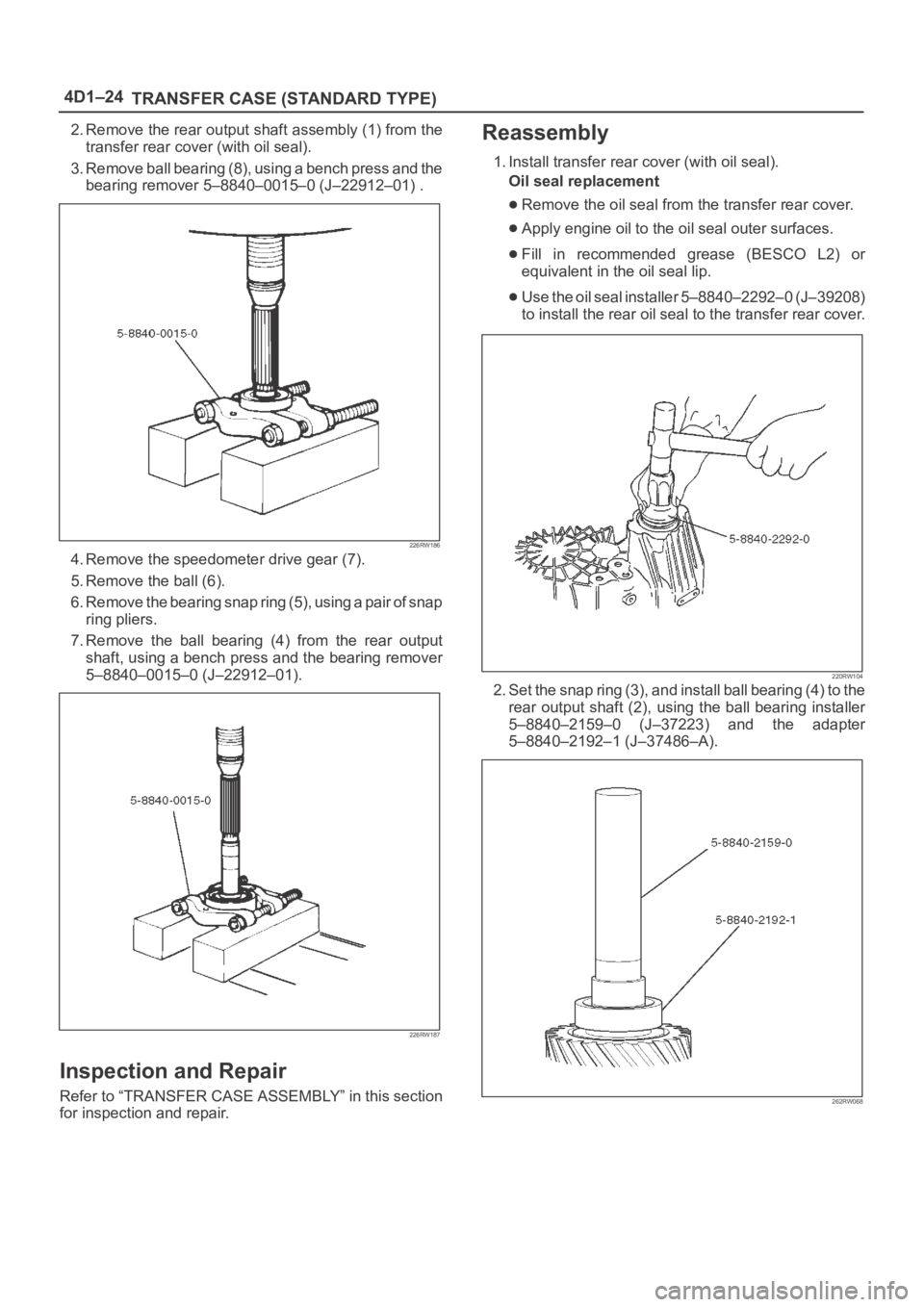
2. Remove the rear output shaft assembly (1) from the
transfer rear cover (with oil seal).
3. Remove ball bearing (8), using a bench press and the
bearing remover 5–8840–0015–0 (J–22912–01) .
226RW186
4. Remove the speedometer drive gear (7).
5. Remove the ball (6).
6. Remove the bearing snap ring (5), using a pair of snap
ring pliers.
7. Remove the ball bearing (4) from the rear output
shaft, using a bench press and the bearing remover
5–8840–0015–0 (J–22912–01).
226RW187
Inspection and Repair
Refer to “TRANSFER CASE ASSEMBLY” in this section
for inspection and repair.
Reassembly
1. Install transfer rear cover (with oil seal).
Oil seal replacement
Remove the oil seal from the transfer rear cover.
Apply engine oil to the oil seal outer surfaces.
Fill in recommended grease (BESCO L2) or
equivalent in the oil seal lip.
Use the oil seal installer 5–8840–2292–0 (J–39208)
to install the rear oil seal to the transfer rear cover.
220RW104
2. Set the snap ring (3), and install ball bearing (4) to the
rear output shaft (2), using the ball bearing installer
5–8840–2159–0 (J–37223) and the adapter
5–8840–2192–1 (J–37486–A).
262RW068